Intermec CK30 Programmer's Manual
3270 terminal emulation
Hide thumbs
Also See for CK30:
- Programmer's manual (448 pages) ,
- User manual (210 pages) ,
- Service manual (113 pages)
Table of Contents
Advertisement
Quick Links
Advertisement
Table of Contents

Related Manuals for Intermec CK30


Summary of Contents for Intermec CK30
- Page 1 Programmer's Guide TE 2000t 3270 Terminal Emulation...
- Page 2 The information contained herein is proprietary and is provided solely for the purpose of allowing customers to operate and service Intermec-manufactured equipment and is not to be released, reproduced, or used for any other purpose without written permission of Intermec.
- Page 3 Forward Tab key and added Back Tab key for 2435A keyboards, corrected the Clear key information for the CK30 terminal in Chapter 3, “Using the Terminal’s Keybaord.” Added two VT/ANSI protocol options, revised the 2475, 2481, and 2486 terminal screen sizes, and revised the Code Page option in Chapter 4, “Using the Termi-...
- Page 4 TE 2000 3270 Terminal Emulation Programmer’s Guide...
-
Page 5: Table Of Contents
Contents Before You Begin ............Safety Summary Do not repair or adjust alone First aid... - Page 6 Contents Using the Terminal’s Keyboard 2415 Terminal ............. . . 2415 Cursor Keys 2415 Paging Keys 2415 Tab Keys...
- Page 7 6400 Computer ............. . Characters on the Keyboards Using the 41-Key Keyboard 6400 Cursor Keys...
- Page 8 CK30 Handheld Computer Characters on the Keyboards CK30 Cursor Keys CK30 Paging Keys CK30 Standard Keys CK30 Function Keys CK30 3278 SNA Keys CK30 AID-Generating Keys CK30 Auto-Login Restart CK30 3270 Additional Functions CK31 Handheld Computer Characters on the Keyboards...
- Page 9 Key Sequence to Open Main Menu Opening the Main Menu 2415, 2425, 2435A, 2455, 2475, 248X Menus 6400, 5055, 59XX, 17XX, 11XX Menus 5020, 700 Series, CK30, CK31, CV60 Menus ™ TE 2000 3270 Terminal Emulation Programmer’s Guide ..........
- Page 10 59XX, 17XX, 11XX) 4) Display Opts (700 Series, CK30, CK31, CV60) 5) Radio Comm (Blank for 5020, 700 Series, CK30, CK31, CV60, and for 2415, 2425, 2435A, 2455, 2475, 248X Terminals without either an 802.1x Sup- plicant Radio Driver or UDP Plus)
- Page 11 59XX, 17XX, 11XX Terminals 700 Series, CK30, CK31, CV60 Terminals Disabling the Auto-Login Feature 2415, 2425, 2435A, 2455, 2475, 248X Terminals 5020, 700 Series, CK30, CK31, CV60 Terminals 6400, 5055 Terminals 59XX, 17XX, 11XX Terminals Sample Auto-Login Script Files Auto-Login Restart Creating a Custom Parameter Set-Up File CONFIG.DAT Settings...
- Page 12 ............2415, 2425, 2435A, 2455, 2475, 248X Terminals 5020, 700 Series, CK30, CK31, CV60 Terminals 6400, 5055 Terminals...
- Page 13 3270 Data Stream Commands Erase All Unprotected Command Erase/Write Command Erase/Write Alternate Command Read Buffer (RB) Command Read Modified Command Read Modified All Command Reset Terminal System Services Control Point (SSCP) Command Write Command Write Control Character 3270 Data Stream Format Orders .
- Page 14 Contents Set Parameters (#H) ............Return Codes for Set Parameters Example of Set Parameters Return Version (#V)
- Page 15 2435A Terminal Display 9 or 10 Columns 12 Columns 17 Columns 19 or 20 Columns 22 Columns 26 Columns 31 or 32 Columns 2455 Terminal Display 20 Columns 33 Columns 40 Columns 53 Columns 80 Columns 2475 and 248X Terminal Displays 10 Columns 12 Columns 17 Columns...
- Page 16 Contents Bar Code Symbologies Bar Code Algorithms ............
-
Page 17: Before You Begin
Safety Summary Your safety is extremely important. Read and follow all warnings and cautions in this document before handling and operating Intermec equipment. You can be seriously injured, and equipment and data can be damaged if you do not follow the safety warnings and cautions. -
Page 18: Safety Icons
Global Services and Support Warranty Information To understand the warranty for your Intermec product, visit the Intermec web site at www.intermec.com and click Service & Support. The Intermec Global Sales & Service page appears. From the Service & Support menu, move your pointer over Support, and then click Warranty. -
Page 19: Telephone Support
Installations Ordering Products Outside the U.S.A. and Canada, contact your local Intermec representative. To search for your local representative, from the Intermec web site, click Contact. Who Should Read this Guide? This guide provides you with information about the TE 2000 3270 ap- plication, and how to install, configure, operate, maintain, and trouble- shoot the application. -
Page 20: Related Documents
Before You Begin Related Documents This table contains a list of related Intermec documents and part numbers. Manual 1100 Series Data Terminal User’s Guide 5020 Data Collection PC User’s Manual 5055 Data Collection PC User’s Guide 5900 Series User’s Guide 700 Series Color Mobile Computer Quick Start Guide 700 Series Color Mobile Computer User’s Manual... -
Page 21: Getting Started
Getting Started This chapter introduces the TE 2000t 3270 application. ™ TE 2000 3270 Terminal Emulation Programmer’s Guide... -
Page 22: Understanding Network Protocol Options
S UDP Plus The terminal communicates with the host computer through the Intermec S TCP/IP The terminal communicates through an Intermec access point, which is directly connected to the host computer on an Ethernet or a token ring network. S WTP... -
Page 23: Starting The Te 2000 Application
3270 commands. ™ TE 2000 3270 Terminal Emulation Programmer’s Guide COPR. 1991-2005 INTERMEC. ALL RIGHTS RESERVED V<version number> <release date> TE 2000(TM) <program name> <version> <emulation type>... -
Page 24: Performing A Quick Configuration
Chapter Getting Started Performing a Quick Configuration Note: For Terminal Emulation Version 6.60 or greater, the default data stream is “VT/ANSI.” 1 Change the data stream to “3270.” The default data stream is “Native” for the 6400 (WTP), 5055 (WTP), 11XX, 17XX, and 59XX Terminals. The default data stream for 2415, 2425, 2435A, 2455, 2475, 248X, and IP terminals is “3270.”... -
Page 25: Configuring The Te 2000 Application
Configuring the TE 2000 Application You can use the terminal’s TE 2000 configuration menus to configure site-specific operational parameters, including UDP Plus, WTP, or TCP/ IP communications, terminal emulation options, and the Main Menu password. For information about configuring the terminal, see Chapter 4, “Using the Terminal Emulation Menus.”... -
Page 26: Program Names
Transmission) or regular UHF. “S-UHF” is synthesized UHF. Model 2415, 2425, 2435A, 2455, 2475, 248X TE/WTP/2.4 GHz OpenAir 6400 5020 5055 59XX 17XX 11XX 700 Series CK30, CK31 CV60 Option TE/WTP/802.11 TE/UDP Plus/2.4 GHz OpenAir TE/UDP Plus/802.11 TE/IP/2.4 GHz OpenAir TE/IP/802.11 TE/WTP/2.4 GHz OpenAir TE/WTP/802.11 TE/WTP/900 MHz Falcon TE/IP/2.4 GHz OpenAir... -
Page 27: Using Terminal Emulation Applications
This chapter describes how to use the TE 2000t 3270 application for your particular terminal. For this application, Intermec Technologies emu- lates an IBM-3278-2 terminal. ™ TE 2000 3270 Terminal Emulation Programmer’s Guide Using Terminal Emulation Applications... -
Page 28: Annunciators
Chapter Using Terminal Emulation Applications Annunciators The terminal’s display reserves a location for annunciators (icons) that help you monitor RF and network communications, or alert you of a condition that requires action. Following are TE 2000 3270 annunciators. Input inhibited Insert mode For information about annunciators that indicate battery condition and general operational status, refer to the terminal’s user manual. -
Page 29: Aid-Generating Keys
AID-Generating Keys The terminal emulates all of the following Attention Identification (AID) keys on the IBM terminal. Clear Programmable function keys F1–F24 These keys send modified input fields and AID key values to the host. The Program Access (PA) keys 1–3 To enter an AID Key: Press the keys listed in the chapter for the terminal. -
Page 30: 3270 Serial Scanning
Chapter Using Terminal Emulation Applications 3270 Serial Scanning The following instructions explain how to set serial scanning options. These instructions apply to the 2415, 2425, 2435A, 2455, 2475, and 248X Terminals. 1 Connect your terminal to a serial scanner. 2 Open the TRAKKER Antares 2400 Menu System. 3 From the Main Menu, choose Configuration Menu >... -
Page 31: Te 2000 ™ 3270 Terminal Emulation Programmer's Guide
Your terminal has a special keyboard that contains most of the keys avail- able on your 3270 terminal keyboard. Use the keyboard to enter data in the TE 2000 screens. The keys on the keyboard have their main character or operation marked directly on the key itself. -
Page 32: 2415 Terminal
Chapter Using the Terminal’s Keyboard 2415 Terminal Your 2415 Terminal has either a 55-key or a 37-key keyboard. For help with using the keyboard, refer to the TRAKKER Antares 241X Hand-Held Terminal User’s Manual (P/N 069538). 55-Key Keyboard Function Left Key Shift Key This illustration shows both a 55-key (left) and a 37-key (right) keyboard for the 2415 Terminal. -
Page 33: 2415 3278 Sna Keys
2415 3278 SNA Keys To Enter Clr (E-Inp) Enter Home Insert New Line (Return) Reset ™ TE 2000 3270 Terminal Emulation Programmer’s Guide Chapter 3 Using the Terminal’s Keyboard Press the Keys 55-Key Keyboard 37-Key Keyboard... -
Page 34: 2415 Aid-Generating Keys
Chapter Using the Terminal’s Keyboard 2415 AID-Generating Keys To Enter Clear 2415 Auto-Login Restart To enter Auto-Login Restart, scan the following bar code (also in Appen- dix A, “Bar Code Scanning”). Auto-Login Restart */EALRS* *%ALRS* Press the Keys 55-Key Keyboard ™... -
Page 35: 2425 Terminal
2425 Terminal For help with using the keyboard, refer to the TRAKKER Antares 2420 and 2425 Hand-Held Terminal User’s Manual (P/N 064024). Function Left (FnL) Key Shift Key This illustration shows the keyboard for the 2425 Terminal. 2425 Cursor Keys To Enter Window/viewport up Window/viewport down... -
Page 36: 2425 3278 Sna Keys
Chapter Using the Terminal’s Keyboard 2425 3278 SNA Keys To Enter Clr (E-Inp) Enter Home Insert New Line (Return) Reset Press the Keys ™ TE 2000 3270 Terminal Emulation Programmer’s Guide... -
Page 37: 2425 Aid-Generating Keys
2425 AID-Generating Keys To Enter Clear 2425 Auto-Login Restart To enter Auto-Login Restart, press ( % or scan the following bar code (also in Appendix A, “Bar Code Scanning”). Auto-Login Restart */EALRS* *%ALRS* ™ TE 2000 3270 Terminal Emulation Programmer’s Guide Chapter 3 Using the Terminal’s Keyboard Press the Keys... -
Page 38: 2435A Terminal
Chapter Using the Terminal’s Keyboard 2435A Terminal For help with using the keyboard, refer to the TRAKKER Antares 243X Hand-Held Terminal User’s Manual (P/N 071791-001). 57-Key Keyboard Your 2435A Terminal has either a 57-key (left), a 48-key (middle), or a 39-key (right) keyboard as shown in this illustration. Characters on the Keyboards The special characters and functions printed above the keys are color- coded to correspond with the matching shift keys. -
Page 39: 2435A Paging Keys
2435A Paging Keys To Enter Page up Page down Page right Page left 2435A Tab Keys To Enter Forward Tab Back Tab 2435A Standard Keys To Enter 57-Key Keyboard 0–9 – Symbols plus corresponding key 2435A Function Keys To Enter Backspace Caps Lock Return... -
Page 40: 2435A 3278 Sna Keys
Chapter Using the Terminal’s Keyboard 2435A 3278 SNA Keys To Enter Clr (E-Inp) Enter Home Insert New Line (Return) Reset Press the Keys 57-Key Keyboard 48-Key Keyboard >, P Green >, D Green >, O Green >, H Green >, I Green >, ;... -
Page 41: 2435A Aid-Generating Keys
2435A AID-Generating Keys To Enter Clear ™ TE 2000 3270 Terminal Emulation Programmer’s Guide Chapter 3 Press the Keys 57-Key Keyboard 48-Key Keyboard >, 1 Orange >, 2 Orange >, 3 Orange >, 4 Orange >, 5 Orange >, 6 Orange >, 7 Orange... -
Page 42: 2435A Auto-Login Restart
Chapter Using the Terminal’s Keyboard 2435A Auto-Login Restart To enter Auto-Login Restart, press r 39-key function numeric keyboards; press Green keyboard, or scan the following bar code (also in Appendix A, “Bar Code Scanning”). Auto-Login Restart */EALRS* *%ALRS* 2435A 3270 Additional Functions To access the TE configuration menus, press r l on the 57-key key- board and 39-key function numeric keyboards, or press Green Orange... -
Page 43: 2455 Terminal
2455 Terminal For help with using the keyboard, refer to the TRAKKER Antares 2455 Vehicle-Mount Terminal User’s Manual (P/N 067358). Note: You must use the 2455 keyboard (P/N 067028) with the TE ap- plications. Shift This illustration shows the keyboard for the 2455 Terminal. 2455 Cursor Keys To Enter Window/viewport up... -
Page 44: 2455 3278 Sna Keys
Chapter Using the Terminal’s Keyboard 2455 3278 SNA Keys To Enter Clr (E-Inp) Enter Home Insert New Line (Return) Reset Press the Keys ™ TE 2000 3270 Terminal Emulation Programmer’s Guide... -
Page 45: 2455 Aid-Generating Keys
2455 AID-Generating Keys To Enter Clear 2455 Auto-Login Restart To enter Auto-Login Restart, press ( ¶ or scan the following bar code (also in Appendix A, “Bar Code Scanning”). Auto-Login Restart */EALRS* *%ALRS* ™ TE 2000 3270 Terminal Emulation Programmer’s Guide Chapter 3 Using the Terminal’s Keyboard Press the Keys... -
Page 46: 2475 And 248X Terminals
Chapter Using the Terminal’s Keyboard 2475 and 248X Terminals For help with using the keyboard, refer either to the Trakker Antares 2475 Vehicle-Mount Terminal User’s Manual (P/N: 072383) or the TRAKKER Antares 248X Stationary Terminal User’s Manual (P/N 066960). This illustration shows the keyboard for the 2475 and 248X Terminals. 2475 and 248X Cursor Keys To Enter Window/viewport up... -
Page 47: 2475 And 248X 3278 Sna Keys
2475 and 248X 3278 SNA Keys To Enter Clr (E-Inp) Enter Home Insert New Line (Return) Reset ™ TE 2000 3270 Terminal Emulation Programmer’s Guide Chapter 3 Using the Terminal’s Keyboard Press the Keys or Enter... -
Page 48: 2475 And 248X Aid-Generating Keys
Chapter Using the Terminal’s Keyboard 2475 and 248X AID-Generating Keys To Enter Clear 2475 and 248X Auto-Login Restart To enter Auto-Login Restart, press ( ¶ or scan the following bar code (also in Appendix A, “Bar Code Scanning”). Auto-Login Restart */EALRS* *%ALRS* Press the Keys... -
Page 49: 6400 Computer
6400 Computer For help with the keyboard, see the PEN*KEY Model 6400 User’s Guide (P/N 961-047-093). 51-Key Keyboard Your 6400 Computer has either a 51-key (left) or a 41-key (right) keyboard as shown. Characters on the Keyboards The special characters and functions printed above the keys are color- coded to correspond with the matching shift keys. -
Page 50: Using The 41-Key Keyboard
Chapter Using the Terminal’s Keyboard Note: The keyboard does not have keys for the “Not” symbol (¬) and the “cent” symbol (¢). To enter these symbols, scan the following bar codes (also in Appendix A, “Bar Code Scanning”). Cent (¢) */ECENT* *%CENT* Not (¬) -
Page 51: 6400 Paging Keys
6400 Paging Keys To Enter Page up Page down Page right Page left 6400 Tab Keys To Enter Back Tab Forward Tab 6400 3278 SNA Keys This chart describes 3278 SNA keys in standard (nonalpha-lock mode). To Enter Clear Home Delete Enter Insert... -
Page 52: 6400 Aid-Generating Keys
Chapter Using the Terminal’s Keyboard 6400 AID-Generating Keys To Enter Clear When alpha lock mode is engaged on the 41-key keyboard, it switches the function keys with the alphabetic keys. That is, function keys normally in the primary plane ([F1] through [F12]) move to the Blue plane. Function keys normally in the Shift plane ([F13] through [F24]) move to the Shift, Blue plane. -
Page 53: 6400 Auto-Login Restart
The following chart describes how to do function operations when the 41-key keyboard is in standard mode or alpha lock mode. To Enter To engage alpha lock mode, press [Blue], [Gold]. Then press the correct key combinations in the chart. The keyboard stays in alpha lock mode until you press [Blue], [Gold] again to unlock it. -
Page 54: 5020 Data Collection Pc
Chapter Using the Terminal’s Keyboard 5020 Data Collection PC For help with using the keyboard, refer to the 5020 Data Collection PC User’s Manual (P/N 068975-002). 55-Key Keyboard Your 5020 Data Collection PC has either a 55-key (left) or a 43-key (right) keyboard as shown. Characters on the 5020 Keypad Characters, symbols, and functions are printed in four places on or above the keys and are also color-coded to make key combinations. -
Page 55: 5020 Cursor Keys
5020 Cursor Keys To Enter Window/viewport up Window/viewport down Window/viewport right Window/viewport left 5020 Paging Keys To Enter Page up Page down Page right Page left 5020 Standard Keys To Enter Numbers Symbols 5020 3278 SNA Keys To Enter Clr (E-Inp) Home Delete Enter... -
Page 56: 5020 Top-Row Function Keys
Chapter Using the Terminal’s Keyboard 5020 Top-Row Function Keys Note: Intermec tion. To Enter F5 (Break) Application Servers do not support the F5 (Break) func- Press the Keys 55-Key Keyboard ™ TE 2000 3270 Terminal Emulation Programmer’s Guide 43-Key Keyboard... -
Page 57: 5020 Caps Lock
5020 Caps Lock To type all alphabetic characters as uppercase letters, either press u be- fore typing each letter or enable the Caps Lock feature. To enable Caps Lock: Press u until a tone is emitted, or press B ? with the 43-key key- board or C u with the 55-key keyboard. -
Page 58: 5055 Data Collection Pc
Chapter Using the Terminal’s Keyboard 5055 Data Collection PC For help with using the keyboard, refer to the 5055 Data Collection PC User’s Guide (P/N 961-054-017). This illustration shows the keyboard for the 5055 Data Collection PC. Characters on the Keyboard The special characters and functions printed on the overlay are color-coded to correspond with the matching shift keys. -
Page 59: 5055 Cursor Keys
5055 Cursor Keys To Enter Window/viewport up Window/viewport down Window/viewport right Window/viewport left 5055 Paging Keys To Enter Page up Page down Page right Page left 5055 Tab Keys To Enter Back Tab Forward Tab 5055 3278 SNA Keys To Enter Clear Home Delete... -
Page 60: 5055 Aid-Generating Keys
Chapter Using the Terminal’s Keyboard 5055 AID-Generating Keys To Enter Clear 5055 Auto-Login Restart To enter Auto-Login Restart, scan the following bar code (also in Appen- dix A, “Bar Code Scanning”). Auto-Login Restart */EALRS* *%ALRS* Press the Keys [Gold] [C] [F1] [F2] [F3]... -
Page 61: 59Xx Terminal
59XX Terminal For help with using the keyboard, refer to the 5900 Series User’s Guide (P/N 961-047-121). This illustration shows the keyboard for the 59XX Terminal. Characters on the Keyboard The special characters and functions printed on the overlay are color-coded to correspond with the matching shift keys. -
Page 62: 59Xx Cursor Keys
Chapter Using the Terminal’s Keyboard 59XX Cursor Keys To Enter Window/viewport up Window/viewport down Window/viewport right Window/viewport left 59XX Paging Keys To Enter Page up Page down Page right Page left 59XX 3278 SNA Keys To Enter Clear Home Delete Enter Insert Reset... -
Page 63: 59Xx Aid-Generating Keys
59XX AID-Generating Keys To Enter Clear 59XX Auto-Login Restart To enter Auto-Login Restart, scan the following bar code (also in Appen- dix A, “Bar Code Scanning”). Auto-Login Restart */EALRS* *%ALRS* ™ TE 2000 3270 Terminal Emulation Programmer’s Guide Chapter 3 Using the Terminal’s Keyboard Press the Keys [Gold] [.] (period) -
Page 64: 17Xx Terminal
Chapter Using the Terminal’s Keyboard 17XX Terminal For help with using the keyboard, refer to the RT17XX Radio Data Termi- nal User’s Guide (P/N: 961-047-068). Your 17XX Terminal has either a 57-key (left) or a 37-key (right) keyboard as shown. Characters on the Keyboards The special characters and functions printed on the overlay are color-coded to correspond with the matching shift keys. -
Page 65: 37-Key Keyboard
37-Key Keyboard The 37-key keyboard has standard numeric keys, an [ENTER] key, and user-defined function keys in its primary plane. It has alphabetic keys and special characters in its secondary plane. Because a terminal with a 37-key keyboard does not have alphabetic keys in its primary plane, follow these procedures when using its firmware and downloading software to it: S To access password-protected menus, press [Gold], [Black], [F12], [F11] or press [Black], [F3], [Black], then type “52401”for a password. -
Page 66: 17Xx Cursor Keys
Chapter Using the Terminal’s Keyboard 17XX Cursor Keys To Enter Window/viewport up Window/viewport down Window/viewport right Window/viewport left 17XX Paging Keys To Enter Page up Page down Page right Page left 17XX Tab Keys To Enter Back Tab Forward Tab 17XX 3278 SNA Keys To Enter Clear... -
Page 67: 17Xx Aid-Generating Keys
17XX AID-Generating Keys To Enter Clear 17XX Auto-Login Restart To enter Auto-Login Restart, scan the following bar code (also in Appen- dix A, “Bar Code Scanning”). Auto-Login Restart */EALRS* *%ALRS* ™ TE 2000 3270 Terminal Emulation Programmer’s Guide Chapter 3 Using the Terminal’s Keyboard Press the Keys 57-Key Keyboard... -
Page 68: 11Xx Terminal
Chapter Using the Terminal’s Keyboard 11XX Terminal For help with using the keyboard, see the 1100 Series Data Terminal User’s Guide (P/N 961-047-069). This illustration shows the keyboard for the 11XX Terminal. Characters on the Keyboard The special characters and functions printed on the overlay are color-coded to correspond with the matching shift keys. -
Page 69: 11Xx Cursor Keys
11XX Cursor Keys To Enter Window/viewport up Window/viewport down Window/viewport right Window/viewport left 11XX Paging Keys To Enter Page up Page down Page right Page left 11XX Tab Keys To Enter Back Tab Forward Tab 11XX 3278 SNA Keys To Enter Clear Home Delete... -
Page 70: 11Xx Aid-Generating Keys
Chapter Using the Terminal’s Keyboard 11XX AID-Generating Keys To Enter Clear 11XX Auto-Login Restart To enter Auto-Login Restart, scan the following bar code (also in Appen- dix A, “Bar Code Scanning”). Auto-Login Restart */EALRS* *%ALRS* Press the Keys [Black] [1] [Black] [A] [Black] [B] [Black] [C]... -
Page 71: 700 Series Mobile Computer
700 Series Mobile Computer For help with using the 700 Series Computer, refer to the 700 Series Monochrome Mobile Computer User’s Manual (P/N 961-054-032) or the 700 Series Color Mobile Computer User’s Manual (P/N: 961-054-031). 700 Series Software Input Panels With the Software Input Panels (SIPs), you can change the color of up to ten keys, given four color choices (including the original gray. -
Page 72: 700 Series Keypads
Chapter Using the Terminal’s Keyboard 700 Series Keypads This illustration shows a 700 Series Monochrome Mobile Computer (left), a 700 Series Color Mobile Computer with a regular keyboard (middle), and a 700 Series Color Mobile Computer with an alpha keyboard (right). Note: The following key sequences are based on the SIP keyboards unless otherwise noted. -
Page 73: 700 Series Standard Keys
700 Series Standard Keys Note: See the 700 Series Mobile Computer User’s Manual for information how to enter alpha characters using the 700 Series Computer keypads. Keep in mind the Alpha key (F or d) and the Caps key (1 or g) are toggle keys —... - Page 74 Chapter Using the Terminal’s Keyboard 700 Series Alphanumeric Characters (continued) To Enter Press the Numeric Keys F 1 2 F 1 2 2 F 1 2 2 2 F 1 3 F 1 3 3 F 1 3 3 3 F 1 4 F 1 4 4 F 1 4 4 4...
-
Page 75: 700 Series Function Keys
700 Series Function Keys To Enter Back Tab Forward Tab Lock Return Shift Space bar Clear 700 Series Editing Keys To Enter E-Inp Enter Home Insert New Line (Return) Reset Note: Pressing E on the 700 Series Numeric Keypad or pressing E on the 700 Color Alphanumeric Keypad also performs the Reset function. -
Page 76: 700 Series Auxiliary Keys
Chapter Using the Terminal’s Keyboard 700 Series Auxiliary Keys To Enter - (hyphen) , (comma) . (period) _ (underscore) Enter Note: For the F11–F24 keys, press either the uppercase sequence or the lowercase sequence (separated by the “or” conjunction), but not both. Keep in mind the Alpha key (F or d) and the Caps key (1 or g) are toggle keys —... -
Page 77: 700 Series Auto-Login Restart
700 Series Auto-Login Restart To enter Auto-Login Restart, tap the SIP lowing bar code (also in Appendix A, “Bar Code Scanning”). Auto-Login Restart */EALRS* *%ALRS* ™ TE 2000 3270 Terminal Emulation Programmer’s Guide Chapter 3 Using the Terminal’s Keyboard keys or scan the fol-... -
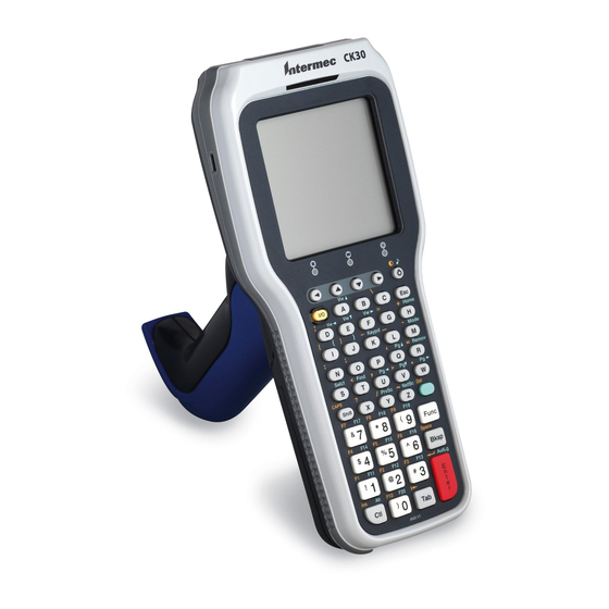
Page 78: Ck30 Handheld Computer
CK30 Handheld Computer Your CK30 Handheld Computer has a 52-key, a 50-key, or a 42-key keyboard. Orange This illustration shows the CK30 52-Key Keyboard on the left and the 50-key keyboard on the right. 52-Key Keyboard Green ™ TE 2000 3270 Terminal Emulation Programmer’s Guide... -
Page 79: Characters On The Keyboards
For help with using the CK30, refer to the CK30 Handheld Computer User’s Manual (P/N 073528). Orange This illustration shows the CK30 42-Key Keyboard. Characters on the Keyboards The special characters and functions printed above the keys are color- coded to correspond with the matching shift keys. The shift keys are:... -
Page 80: Ck30 Paging Keys
[Shift] plus corresponding CK30 Function Keys To Enter Backspace Caps Lock Ctrl Forward Tab Return Shift Space bar CK30 3278 SNA Keys To Enter Clr (E-Inp) Enter Home Insert New Line (Return) Reset Press the Keys 52-Key Keyboard 50-Key Keyboard... -
Page 81: Ck30 Aid-Generating Keys
CK30 AID-Generating Keys To Enter Clear CK30 Auto-Login Restart To enter Auto-Login Restart, press keyboards, press ing bar code (also in Appendix A, “Bar Code Scanning”). Auto-Login Restart */EALRS* *%ALRS* ™ TE 2000 3270 Terminal Emulation Programmer’s Guide Chapter 3... -
Page 82: Ck30 3270 Additional Functions
Chapter Using the Terminal’s Keyboard CK30 3270 Additional Functions To access the TE configuration menus, press [Alt] [M] on the 52-key key- board, press on the 42-key keyboard. [Ctl] [M] on the 50-key keyboard, or press [Alt] ™ TE 2000 3270 Terminal Emulation Programmer’s Guide... -
Page 83: Ck31 Handheld Computer
CK31 Handheld Computer Your CK30 Handheld Computer has a 52-key keyboard. For help with using the CK31, refer to the CK31 Handheld Computer User’s Manual (P/N . Orange This illustration shows the CK31 52-Key Keyboard. Characters on the Keyboards The special characters and functions printed above the keys are color- coded to correspond with the matching shift keys. -
Page 84: Ck31 Paging Keys
Chapter Using the Terminal’s Keyboard CK31 Paging Keys To Enter Page up Page down Page right Page left CK31 Standard Keys To Enter 0–9 Symbols CK31 Function Keys To Enter Backspace Caps Lock Ctrl Forward Tab Return Shift Space bar CK31 3278 SNA Keys To Enter Clr (E-Inp) -
Page 85: Ck30 Aid-Generating Keys
CK30 AID-Generating Keys To Enter Clear CK31 Auto-Login Restart To enter Auto-Login Restart, press scan the following bar code (also in Appendix A, “Bar Code Scanning”). Auto-Login Restart */EALRS* *%ALRS* ™ TE 2000 3270 Terminal Emulation Programmer’s Guide Chapter 3 Using the Terminal’s Keyboard... -
Page 86: Ck31 3270 Additional Functions
Chapter Using the Terminal’s Keyboard CK31 3270 Additional Functions To access the TE 2000 configuration menus, press [Alt] [M] on the 52-key keyboard. ™ TE 2000 3270 Terminal Emulation Programmer’s Guide... -
Page 87: Cv60 Vehicle Mount Computer
CV60 Vehicle Mount Computer For help with using the CV60 Vehicle Mount Computer, refer to the CV60 Vehicle Mount Computer User’s Guide (P/N 961-054-033). Characters on the Keyboards The special characters and functions printed above the keys are color- coded to correspond with the matching shift keys. The shift keys are: [Blue] [Gold] CV60 Software Input Panels... - Page 88 Chapter Using the Terminal’s Keyboard The illustration above shows the Software Input Panels (SIPs) for the VT/ANSI application. Tap the Mn Tap the Shift Tap the toggle key Tap the Cap _ key to use uppercase keys with numbers. Tap the Cap _ key, then the Shift key off the Shifted keyboard to get to the TE 2000 Setup Menus.
-
Page 89: Cv60 Keyboard
CV60 Keyboard Note: You must use the 3270 keyboard (P/N: 850-551-005) with the TE applications. Blue Gold This illustration shows the keyboard for the CV60 Vehicle Mount Computer. CV60 Cursor Keys To Enter Window/viewport up Window/viewport down Window/viewport right Window/viewport left CV60 Paging Keys To Enter Page up... -
Page 90: Cv60 Tab Keys
Chapter Using the Terminal’s Keyboard CV60 Tab Keys To Enter Back Tab Forward Tab CV60 3278 SNA Keys To Enter Clr (E-Inp) Enter Home Insert New Line (Return) Reset Press the Alphanumeric Keys → → [Shift] Press the Alphanumeric Keys [Blue] [C] [Del] [Enter]... -
Page 91: Cv60 Aid-Generating Keys
CV60 AID-Generating Keys To Enter Clear CV60 Auto-Login Restart To enter Auto-Login Restart, press [Blue] [Menu], tap the SIP keys, or scan this bar code (also in Appendix A, “Bar Code Scanning”). Auto-Login Restart */EALRS* *%ALRS* ™ TE 2000 3270 Terminal Emulation Programmer’s Guide Chapter 3 Press the Alphanumeric Keys [Yellow] [C]... - Page 92 — Chapter Using the Terminal’s Keyboard ™ TE 2000 3270 Terminal Emulation Programmer’s Guide...
-
Page 93: Using The Terminal Emulation Menus
CFGLIT.DAT. To customize CFGLIT.DAT, see Chapter 5, “Customiz- ing Your Configuration.” Note: For 700 Series, CK30, CK31, and CV60 Terminals with firmware versions 8.00 or greater, if a CONFIG.DAT file is present on your terminal, its settings are backed up in a CONFIG.OLD file, then written into a TE_SETTINGS.INI file. -
Page 94: Function Keys
Chapter Using the Terminal Emulation Menus Function Keys These paragraphs describe how to navigate through the TE 2000 configu- ration menus. Enter Key Press the terminal [Enter] key to return to a previous TE configuration menu. Press [Enter] several times to return to the Main Menu from a sub- menu. -
Page 95: Up And Down Arrows
Up and Down Arrows For 6400, 5055, 11XX, the up and down arrow keys are defined by the host computer. For 59XX, the up and down arrow keys can be made to function more effi- ciently, in many cases, by pressing the FUNC or ALT key, then pressing the desired arrow key. -
Page 96: Display Position 1
Chapter Using the Terminal Emulation Menus Display Position 1 If the radio icon is displayed in position 0, then position 1 shows the radio transmission status (either receiving, sending, communication loss, or mes- sage waiting). If there is no radio icon shown in position 0, then this posi- tion is blank and position 1 shows the active session number 1 or 2. -
Page 97: Display Position 4
Shift Mode (Yellow or Gold for 6400, 5055, 11XX, 17XX; varies for 59XX) " The keyboard is in a colored shift mode — keystrokes enter the symbol or perform the function shown on the overlay to the upper right of the key. Display Position 4 Alpha Lock (6400) This symbol is used only for the 6400 Computer 41-key keyboard model. -
Page 98: Display Positions 4 Through 8
Chapter Using the Terminal Emulation Menus Display Positions 4 through 8 XX/YY Current Row/Column Position (59XX) Shows the current location of the cursor, with “XX” as the row position and “YY” as the column position. For example, if the cursor is at row 5, column 12, the annunciators will show “05/12”... -
Page 99: Configuration Menus (700 Series, Ck31, Cv60)
Configuration Menus (700 Series, CK31, CV60) When a user taps the Menu Settings button (”M” circled in this illustra- tion) on the toolbar, the following menu appears: S Select Menu Settings to configure the contents of this menu. Enter a password, the default being cr52401. - Page 100 Chapter Using the Terminal Emulation Menus S Select Scanner Test to scan bar codes and view the bar code read and its length. The first character of the bar code is the bar code type character. Select ok or press Enter to exit this test. S Select Keyboard Test to view the hex value of the pressed key and the actual key value.
-
Page 101: Configuring Te Parameters
This chapter contains the TE configuration menus for the following termi- nals: 2415, 2425, 2435A, 2455, 2475, 248X, 6400, 5020, 5055, 59XX, 17XX, 11XX, 700 Series, CK30, CK31, and CV60 unless otherwise no- ted. Additional information is available for each of the following:... -
Page 102: Opening The Main Menu
Chapter Using the Terminal Emulation Menus Note: You can also scan this bar code label to access the Main Menu. TE configuration menus */ETECFG* *%TECFG* Opening the Main Menu The Main Menu is the first screen displayed when you open the computer menus. - Page 103 1) Set-up Parms (2415, 2425, 2435A, 2455, 2475, 248X) This is password-protected to prevent unauthorized users from changing parameters. You can customize the parameter’s CONFIG.DAT setup file to change the password. See Chapter 5, “Customizing Your Configuration.” Changed parameters apply to the current session. If more than one session is available, use the 7) More >...
-
Page 104: 6400, 5055, 59Xx, 17Xx, 11Xx Menus
Chapter Using the Terminal Emulation Menus 6400, 5055, 59XX, 17XX, 11XX Menus The following menus pertain to the 6400, 5055, 59XX, 17XX, and 11XX Terminals. To return to the Main Menu, press the [Enter] key several times, then se- lect 6) Exit Menus, to return to the operating system. Set-up Parms 1) Communication 2) Barcode Parms... - Page 105 1) Set-up Parms (6400, 5055, 59XX, 17XX, 11XX) This is password-protected to prevent unauthorized users from changing parameters. You can customize the parameter’s CONFIG.DAT setup file to change the password. See Chapter 5, “Customizing Your Configuration.” Changed parameters apply to the current session. If more than one session is available, use the 7) More >...
-
Page 106: 5020, 700 Series, Ck30, Ck31, Cv60 Menus
Using the Terminal Emulation Menus 5020, 700 Series, CK30, CK31, CV60 Menus The following menus pertain to the 5020, 700 Series, CK30, CK31, and CV60 Terminals. To return to the Main Menu, press the [Enter] key several times, then se- lect 6) Exit Menus, to return to the operating system. - Page 107 1) Host View Sze 2) Data Stream 3) Extended Cmds 4) 5250 5) 3270 6) VT220 For 700 Series, CK30, CK31, CV60 1) Backlight is for 1) Backlight 700 Series 2) Cursor Mode 6) Font Quality is 3) Select Font...
-
Page 108: Set-Up Parameters
1) Communication The communication option for the terminals are broken down as follows: S 2415, 2425, 2435A, 2455, 2475, 248X, 5020, 700 Series, CK30, CK31, CV60 with UDP Plus 1) ITC Server via the next paragraph. S 2415, 2425, 2435A, 2455, 2475, 248X with RTC 2) RTC/WTP on page 90. - Page 109 IP address of the host to which you want to connect. Enter the IP ad- dress as four decimal numbers separated by periods. If a terminal was linked with a host name on the Intermec Application Server, or a default host was configured on this Intermec Application Server, you do not need to enter a host name on this screen.
- Page 110 The user can then select the host from the list. S The Intermec Application Server contains multiple hosts. S The terminal is not linked with a host name on the Intermec Applica- tion Server. S The host name is blank.
- Page 111 WTP Stack Options ™ TE 2000 3270 Terminal Emulation Programmer’s Guide Chapter 4 Using the Terminal Emulation Menus Controller Type 2) RTC/WTP Host/Cntl 2) Host/Cntl Host/Cntl 1) CNTL A 2) CNTL B 3) CNTL C ENTER DONE ENTER Controller (x) Enter Unit Number ENTER...
- Page 112 Chapter Using the Terminal Emulation Menus 2) RTC/WTP (6400, 5055, 59XX, 17XX, 11XX) Use 2) RTC/WTP to set, view, or change the terminal ID. This number allows the host computer to identify individual terminals in the radio data network. Each terminal must have a unique number in the same network. The 1) Radio Setup and 2) Host/Cntl menus are shown on the following pages.
- Page 113 For 802.11 Radios Only Radio Setup Network Name xxxx Enter up to 34 char- acters for a name ENTER Radio Setup Radio Config# Set Mode/Channel Set Mode/Channel is for RM60 Use Cursor Up (902 MHz) radios and Down Keys To Adjust DS xxxx channel xx ™...
- Page 114 Chapter Using the Terminal Emulation Menus Host/Cntl Settings DONE 3) Direct Connect (6400, 5055) The first option if exercising TCP/IP stack is 1) Radio Setup. Once se- lected, enter your network name or LAN ID. If using a 902 MHz radio module, use the up and down arrows to pick the Direct Sequence (DS) and Channel configuration.
- Page 115 When designating additional hosts for the 6400 Computer or 5055 PC, you must: S Tell the 6400 Computer or 5055 PC the host type of each host com- puter: (3270, 5250, or VT/ANSI). S Tell the 6400 Computer or 5055 PC the name of each host. Note: Selections in these menus apply only to the current session.
- Page 116 Chapter Using the Terminal Emulation Menus 3) Direct Connect (2415, 2425, 2435A, 2455, 2475, 248X, 5020, 700 Series, CK30, CK31, CV60 with TE/IP) To set these options, select 3) Direct Connect > 2) Host Setup > 1) Host A. Use the Emulation (A) option to tell the terminal the type of each host computer.
-
Page 117: Barcode Parms (2415, 2425, 2435A, 2455, 2475, 248X, 5020)
2) Barcode Parms (2415, 2425, 2435A, 2455, 2475, 248X, 5020) The 2) Barcode Parms (parameters) menus designate whether you are us- ing a bar code scanner and scan options. Barcode Parms 1) Code 39 Encoded 3) Concatenate 4) RS232 Stream 5) Stream Scan 6) Scan All Flds 1) Code 39 Encoded... -
Page 118: Cv60)
Chapter Using the Terminal Emulation Menus 2) Barcode Parms (6400, 5055, 59XX, 17XX, 11XX, 700 Series, CK30, CK31, CV60) Selecting 2) Barcode Parms displays either the Scanner Type menu or the Scan Options menu, pending on your terminal: S For the 6400, 5055, 59XX, 17XX, 11XX Terminals, Selecting 2) Barcode Parms displays the Scanner Type menu. - Page 119 After a bar code is placed in a field, any subsequent read replaces the first read. 4) BC Type Char (6400, 59XX, 17XX, 11XX, 700 Series, CK30, CK31, CV60) This adds a character associated with the bar code type at the beginning of the scanned bar code.
- Page 120 You can configure the symbology parameters under 1) Set-up Parms > 2) Barcode Parms , however these are not used. S 5) Use Wedge Mode (700 Series, CK30, CK31, CV60) This causes the TE 2000 application to use the system Scanners and Symbologies settings.
- Page 121 3) Element Decode 4) START Decode Note: For the 700 Series, CK30, CK31, or CV60 Terminal, this imple- mentation of TE 2000 processes EAN 8 and UPC E bar codes in the same manner. The type character for EAN 8 with Add-On 2 or Add-On 5 will decode as UPC E with Add-On 2 or Add-On 5, respectively.
- Page 122 1) Set-up Parms menu. 5) Code 11 is for 59XX, 17XX, 11XX, 700 Series, CK30, CK31, CV60 3) MOD11 Chk is blank for 700 Series, CK30, CK31, CV60 4) Allow Alpha is for 59XX, 17XX, 11XX Scan Options 2...
- Page 123 Enter this information in the order listed. 1 Key in the maximum length (0–99), then press [Enter]. For the 700 Ser- ies, CK30, CK31, or CV60 Terminals, set this as high as you intend to set the minimum length.
-
Page 124: Protocol Opts
Chapter Using the Terminal Emulation Menus After all of the length options are set for the enabled bar code, the display returns to either the Scan Options menu or the Scan Options 2 menu (pending on from which menu the bar code was enabled). (bar code type) Max Length (bar code type) - Page 125 3) 5250 4) VT/ANSI Note: For 2415, 2425, 2435A, 2455, 2475, 248X, 5020, 700 Series, CK30, CK31, and CV60 Terminals, you can also set the emulation type through the 1) ITC Server or 3) Direct Connect options. ™ TE 2000 3270 Terminal Emulation Programmer’s Guide...
- Page 126 Causes the cursor to automatically tab forward to the next input field when a good scan is obtained. 3) Telnet (blank for 5020, 700 Series, CK30, CK31, CV60) Handles the telnet option negotiations to establish a session with an ap- propriate telnet server.
- Page 127 4) Device Name Enters a physical name for a device. This is 1–10 characters with allowable values of A–Z, a–z, 0–9, the pound symbol (#), the dollar sign ($), the ampersand (@), and an underscore ( _ ). 5250E RFC 1572 Support. Note: The first character of 4) Device Name cannot start with a number (0–9).
- Page 128 Token Ring on your host, the tab key also unlocks the keyboard. 5250 1) Beep On Error 2) Auto Tab Scan 3) Telnet is blank for 5020, 3) Telnet 700 Series, CK30, CK31, CV60 4) Device Name 5) Allow NAWS 6) Skip FldExit 7) More 5250...
- Page 129 Tab Scan. 4) Emulate 3210 (6400, 5055, 59XX, 17XX, 11XX) The Intermec 3210 emulation option allows the 3270 keyboard to emulate an RT3210 Hand-Held Computer, performing the same functions. For full 3210 compatibility, disable buffering the keyboard, set cursor to lazy mode, and set the LCD Parms to Key Uppercase.
- Page 130 Note: 3) Auto Entr Scn cannot be enabled at the same time as 4) Auto Tab Scan. 3270 4) Emulate 3210 is for 6400, 5055, 59XX, 17XX, 11XX 5) Telnet is blank for 5020, 700 Series, CK30, CK31, CV60 3270 VT/ANSI ™ TE 2000 3270 Terminal Emulation Programmer’s Guide...
- Page 131 (hexadecimal 05). The range is 0–30. Default is null string for 2415, 2425, 2435A, 2455, 2475, 248X, 6400, 5020, 5055, 59XX, 17XX, and 11XX Terminals and the terminal’s serial number for 700 Series, CK30, CK31, and CV60 Terminals.
- Page 132 S 2) RS232 Parity (not supported on 5020, 700 Series, CK30, CK31, CV60) Select from Odd, Even, or [None]. S 3) RS232 Stop Bits (not supported on 5020, 700 Series, CK30, CK31, CV60) Select either [1]- or 2-bits. S 4) RS232 Data Bits (not supported on 5020, 700 Series, CK30, CK31, CV60) Select either 7- or [8]-bit.
- Page 133 5) VT Cursor Mode 6) Terminal Mode 7) More S 1) Telnet (blank for 5020, 700 Series, CK30, CK31, CV60) Handles telnet option negotiations to establish a session with an ap- propriate telnet server. Note this cannot be changed if using TCP/IP.
- Page 134 Chapter Using the Terminal Emulation Menus S 2) Term Setup Selects the compliance level of the emulated terminal. Default is VT340 to support all commands. Make a selection, then press [Enter] to return to the 3) Protocol Opts menu. S 3) Send XON Default is enabled which indicates that when an RIS is received from the host, the XON character is returned after compliance of this command.
- Page 135 S 5) VT Cursor Mode Determines what is returned to the host when cursor keys are hit. Default is 2) Cursor. S 1) Application S 2) Cursor S 6) Terminal Mode (VT220/320 only) Sets the terminal mode to 7-bit or 8-bit. This option sets the mode VT-series terminals used to exchange escape sequences, control com- mands, and status reports with an application.
- Page 136 Chapter Using the Terminal Emulation Menus S 3) Terminal ID S 4) Auto Wrap S 5) Allow LineMode S 6) Do Gold Key S 7) More This enables the entry of a character string sent back to the host in response to IAC SB terminal type SE.
- Page 137 Note: 7) Native is enabled by default to preserve backwards compatibility. 7) Native (2415, 2425, 2435A, 2455, 2475, 248X, 6400, and 5055 with WTP, 59XX, 17XX, 11XX) S For 2415, 2425, 2435A, 2455, 2475, 248X with WTP: When enabled, pressing [F1] is equivalent to pressing [FnL] [7] (Home), while pressing [F2] is equivalent to pressing [F1], etc.
-
Page 138: 59Xx, 17Xx, 11Xx)
Chapter Using the Terminal Emulation Menus 4) Display Opts (2415, 2425, 2435A, 2455, 2475, 248X, 5055, 5020, 6400, 59XX, 17XX, 11XX) 4) Display Opts adjusts the backlight timer, the cursor appearance on the display, or the remote display. Display Opts 1) Backlight 2) Cursor Mode 3) Remote Disp... - Page 139 4) Block (6400, 5020, 59XX, 17XX, 11XX) This provides a reverse or highlighted block (J) character displaying the cursor’s current location. Cursor Mode 1) Underline Blink 2) Block Blink 3) Underline 4) Block > < 3) Remote Disp (17XX) This menu allows communication to a remote display. 1) Enabled Press this option to enable the remote display function.
-
Page 140: Display Opts (700 Series, Ck30, Ck31, Cv60)
Chapter Using the Terminal Emulation Menus 4) Display Opts (700 Series, CK30, CK31, CV60) 4) Display Opts adjusts the backlight timer, the cursor appearance on the display, or the remote display. Display Opts 1) Backlight 2) Cursor Mode 3) Select Font... - Page 141 4) Block This provides a reverse or highlighted block (J) character displaying the cursor’s current location. Cursor Mode 1) Underline Blink 2) Block Blink 3) Underline 4) Block > < 3) Select Font Selects a font type to appear on the display. 1) Lucida This displays the font type in Lucida: ABCDEFGHIJKLMNOPQRSTUVWXYZ...
- Page 142 Renders the original foreground color as the new background color and the original background color as the new foreground color. 6) Font Quality (CK30, CK31) Selects either a standard font quality or a clear type font quality to appear on the display.
-
Page 143: Radio Comm
4) Hebrew 5) Central Europe 6) Latin 2 5) Radio Comm (Blank for 5020, 700 Series, CK30, CK31, CV60, and for 2415, 2425, 2435A, 2455, 2475, 248X Terminals without either an 802.1x Supplicant Radio Driver or UDP Plus) Note: Diagnostic modes disable data compression and are reserved for engineering tests. - Page 144 Chapter Using the Terminal Emulation Menus For 2415, 2425, 2435A, 2455, 2475, 248X Terminals with either an 802.1x Supplicant Radio Driver or UDP Plus The following menu appears: 1) User Auth 2) Disconnect Val 1) User Auth (2415, 2425, 2435A, 2455, 2475, 248X Terminals with 802.1x supplicant radio driver) When enabled, the terminal prompts for a user name and password before sending any radio data.
-
Page 145: 17Xx, 11Xx)
3) Security ID (Proxim radios) This changes the radio security identification. Enter the new security ID (up to 16 characters) twice. If the old security ID is not correct or if the second new security ID was not entered correctly, you will see the “un- changed”... -
Page 146: Exit Te2000 (700 Series, Ck30, Ck31, Cv60)
To enable the password, press [1], then type “3193693” for the fixed pass- word set by Intermec Technologies Corporation. The “1)” will change to reverse video to indicate it is enabled. With this enabled, enter this password when you access the terminal emulation menu screens. Press [Enter] until you reach the Main Menu, then press 6) Exit Menus to return to the main terminal screen. - Page 147 Press [1] for the RS-232 driver (default), press [2] for the IrDA driver (6400, 5020, 700 Series, CV60), press [3] for the RF driver (5020); or press [4] for the Pan driver (700 Series, CK30, CK31, CV60). Print Device...
-
Page 148: Lcd Parms (Parameters)
Chapter Using the Terminal Emulation Menus 3) COM Select (248X, 5055) Selects which communications port to use for extended commands, RS-232 communications, or media copy commands. COM Select 1) COM 1 2) COM 2 2) LCD Parms (Parameters) 2) LCD Parms adjusts these Liquid Crystal Display (LCD) features: S The screen size (number of rows displayed, and the number of charac- ters displayed on each row). -
Page 149: Screen Size (Blank For 2480, 2485)
2) Screen Size (blank for 2480, 2485) 2) Screen Size selects the number of lines and characters in each line to be viewed on the display. To change the screen size: 1 Press the arrow keys. Each key press moves the word On one position in the direction of the arrow key pressed. - Page 150 Chapter Using the Terminal Emulation Menus 2435A Terminal Screen Sizes For 2435A Terminals with Terminal Emulation version 6.60 or greater and TE 2000 application version 7.10 or greater, if icons are enabled in the firmware, then the 2435A Terminal uses the following screen sizes. If the icons are disabled in the firmware (default), then the 2435A Termi- nal uses the screen sizes as shown on page 129 for the 2415 and 2425 Ter- minals.
- Page 151 For 2455 Terminals with Terminal Emulation version 6.73 or greater and TE 2000 version 7.15.09 or 7.15.77 or greater, the 2455 Terminals use the following screen sizes. Only one option can be selected at a time. (Default is 25 x 80) S 8 rows, with 20, 33, or 40 characters per row S 12 rows, with 20, 33, 40, 53, or 80 characters per row S 16 rows, with 20, 33, 40, or 53 characters per row...
- Page 152 Chapter Using the Terminal Emulation Menus For 2475, 2481, and 2486 Terminals with Terminal Emulation version 6.73 or greater and TE 2000 application version 7.15.09 or 7.15.77 or great- er, the 2475, 2481, and 2486 Terminals use the following screen sizes. Only one option can be selected at a time.
- Page 153 5020 PC Screen Sizes Choices for the 5020 PC include the following. Only one option can be selected at a time. (Default is 16 x 20) S 8 rows, with 10, 13, 16, 20, 23, 26, or 32 characters per row S 10 rows, with 10, 13, 16, 20, 23, 26, or 32 characters per row S 12 rows, with 10, 13, 16, 20, 23, 26, or 32 characters per row S 14 rows, with 10, 13, 16, 20, 23, 26, or 32 characters per row...
- Page 154 Chapter Using the Terminal Emulation Menus 59XX Terminal Screen Sizes Choices for the 59XX Terminal includes the following. Only one option can be selected at a time. (Default is 12 x 40) S 8 rows, with 40, 60, or 80 columns per row S 10 rows, with 40, 60, or 80 columns per row S 12 rows, with 40, 60, or 80 columns per row S 16 rows, with 40, 60, or 80 columns per row...
- Page 155 S 9 rows, with 12 or 16 characters per row 700 Series, CK30, CK31, CV60 Terminal Screen Sizes Choices for the 700 Series, CK30, and CV60 Terminals include the follo- wing. Only one option can be selected at a time. (Default is 10 x 20) S For 700 Series Computers, enter a value between 8–20 for rows and a...
-
Page 156: Screen Mode
Chapter Using the Terminal Emulation Menus 3) Screen Mode 3) Screen Mode selects the cursor position and movement as you scroll through data in the display buffer. This buffer stores data in a standard CRT format (as sent from the host computer). Since the terminal display is smaller than a CRT, these 3) Screen Mode options optimize your view of information (data) on the display. -
Page 157: Annunciators (Blank For 17Xx, 11Xx)
4) Lazy Mode Starts the cursor in the upper left corner of the terminal display. The cur- sor moves across the display in the scrolled direction. When the cursor goes beyond the edge of the display, the data begins to move in the oppo- site direction that the cursor is moving in and the cursor remains at the edge of the display. -
Page 158: Backlight (59Xx, 17Xx)
Chapter Using the Terminal Emulation Menus 5) Backlight (59XX, 17XX) This adjusts the intensity (brightness) of the display backlight. The intensi- ty can be set from 0 (off) to 15 (fully on). Keep in mind that the backlight uses considerable battery power. To conserve battery power, keep the in- tensity and duration of the backlight as low as possible. -
Page 159: Scroll Window
1) Scroll Window 2) Menu Settings 3) Toolbar Options 1) Scroll Window (700 Series, CK30, CK31, CV60) 1) Scroll Window defines the cursor movement, just how far it moves with each press of the arrow keys. Default is 1) Tab Size. - Page 160 Chapter Using the Terminal Emulation Menus This configures the way menu options are listed when the user taps the Menu Settings button created by the toolbar settings. When this button is pressed, the following menu would appear. See page 79 for information. 3) Toolbar Options (700 Series, CK31, CV60) When you select this option, you are prompted for a password.
- Page 161 In the Current Items box on the right, are the set toolbar values. The items you can include in the toolbar are listed under Available Items on the left.left hand side is the available items that you can add to the toolbar. To select an item, tap that item, then tap the appropriate >>...
- Page 162 Chapter Using the Terminal Emulation Menus S Select “Menu Settings” to add an “M” button to your toolbar. Tap this to access the menu settings selected from the menu settings screen in option two under LCD parms. Default settings bring up this screen: S Select “Switch Session”...
- Page 163 S Select “Signal Indicator” to show the RSSI (Radio or Ready Signal Strength Indicator) which displays the RSSI frequency retrieved from the radio module. The RSSI indicator is updated every 200 millisec- onds. The color scheme is set up as follows. Color Dark Green Light Green...
-
Page 164: Beeper Setup (6400, 5055, 59Xx, 17Xx, 11Xx, Ck30, Ck31)
Exit Note: Press Defaults to reset the toolbar to its default values. 3) Beeper Setup (6400, 5055, 59XX, 17XX, 11XX, CK30, CK31) The 3) Beeper Setup menus adjust the beeper tones for key clicks (presses) and error conditions. For 17XX Terminals, 3) Beeper Select directs the au- dio output to the internal buzzer or to a headset. -
Page 165: Key Click
1) Key Click Use 1) Key Click to adjust the frequency and length (duration) of the sound made when a key is pressed. To adjust the key click tone, press the appropriate option, then press the up/down arrow keys to make the de- sired adjustment. -
Page 166: Error Tone
Chapter Using the Terminal Emulation Menus 2) Error Tone 2) Error Tone adjusts the length and frequency of the tone made when an error occurs (for example, pressing an invalid key). The 2) Error Tone adjustments, and the procedures for making them are identical to the 1) Key Click adjustments. -
Page 167: Tests
4) Tests Intermec Systems Engineers use the 4) Tests menus to verify terminal op- eration during environmental stress tests, peripherals, the display, RF com- munications, and memory. Tests 1) Peripherals 2) Converters 3) Memory View 4) Packet Driver 5) Numbers... - Page 168 Chapter Using the Terminal Emulation Menus S PRI The primary version of low-level radio firmware. S SEC The secondary version of the low-level radio firmware. S RFLINK A general description of the RF connection overall quality between Lu- cent radios in the terminal and radios in the Access Point. The Lucent radio grades the RF link on a scale from 0–92, representing the RF channel Signal-to-Noise Ratio.
- Page 169 2) RS232 Test (6400, 5055, 59XX, 17XX, 11XX) Tests the data communication port on the terminal, requiring a special loop-back connector that links the following input and output pins on the data connector: S TX output to the RX input S DTR output to the DSR input S CTS output to the RTS input To run the test, select 2) RS232 Test, attach the loop-back connector to...
-
Page 170: Converters (59Xx)
Chapter Using the Terminal Emulation Menus 4) Keyboard Test (6400, 5055, 59XX, 17XX, 11XX) Tests each key on the terminal keypad or 5055 external keyboard. Press each key, except the [Enter] key, and a character corresponding to the pressed key should appear on the display. ENTER To exit 5) Scanner Test This option tests the operation of an attached bar code scanner. -
Page 171: Memory View (6400, 5055, 17Xx, 11Xx)
3) Memory View (6400, 5055, 17XX, 11XX) This menu is reserved for engineering test and evaluation. Press [F1] to exit out of this test, [F2] to view the heap, [F3] to view the far heap, or [F4] to do a memory dump. Memory View F1 - Exit F2 - Heap... -
Page 172: Numbers (Blank For 700 Series, Ck30, Ck31, Cv60)
Chapter Using the Terminal Emulation Menus 4) Histogram An Intermec engineer may ask you to access this menu if your terminal has problems. From this menu you can provide the Intermec system engineer with vital information about your unit. The actual menus are not shown in this manual, however some of the gen- eral terminology is shown below. -
Page 173: Exit Menus
6) Exit Menus Note: If direct connect is used, the terminal may reboot upon exiting the TE configuration menu. Use 6) Exit Menus to exit the TE configuration menus. If you changed any parameter settings, the terminal displays the following when you exit the menus. -
Page 174: More (Main Menu 2)
3) Cloning Opts is for 59XX, 17XX, 11XX 4) Session Menu is for 2415 (WTP), 2425 (WTP), 2435A (WTP), 2455 (WTP), 2475 (WTP), 248X (WTP), 6400, 5020 (TCP/IP), 5055, 17XX, 11XX, 700 Series, CK30, CK31, CV60 Input Inhibited annunciator ™ TE 2000... -
Page 175: Cloning Opts (59Xx, 17Xx, 11Xx)
If an error is made or the incorrect password is entered, the terminal will return to 2) Save Parms screen without saving your entries. Save Parms Enter Password: > ..3) Cloning Opts (59XX, 17XX, 11XX) Note: 3) Cloning Opts is disabled for 59XX Terminals. - Page 176 Chapter Using the Terminal Emulation Menus 6 Hold down the [I] key while turning on the terminal receiving the pro- gram. The application program will copy into the receiving terminal. To Source Terminal To Source Terminal This illustrations shows the FLASH cloning cable connections as they pertain to step 1 on the previous page.
-
Page 177: Ck30, Ck31, Cv60 With Tcp/Ip, 6400, 5020, 5055, 59Xx, 17Xx, 11Xx)
4) Session Menu (2415, 2425, 2435A, 2455, 2475, 248X with WTP, 700 Series, CK30, CK31, CV60 with TCP/IP, 6400, 5020, 5055, 59XX, 17XX, 11XX) Note: 2415, 2425, 2435A, 2455, 2475, 248X, 700 Series, CK30, CK31, and CV60 Terminals with UDP Plus do not allow multiple sessions. -
Page 178: Restarting Terminal Emulation
Restarting Terminal Emulation Note: The reset firmware bar code is not supported on the 5020, 59XX, 17XX, 11XX, 700 Series, CK30, CK31, or CV60 Terminals. Instead, do the cold-start function to exit the TE 2000 application and return to the Windows CE main menu. - Page 179 <program name> <version> Host: <host name> <emulation type> Note: If not connected to the Intermec Application Server or host com- puter, or have problems accessing the Main Menu, reset your terminal to go to the initialization screens. 2 Select 1) Set-up Parms, then enter the “cr52401” password. Do not press Enter.
-
Page 180: 2415, 2425, 2435A, 2455, 2475, 248X Terminals
6400 Computer The terminal emulation screens support terminals running Intermec Ter- minal Emulation or 6400 TCP/IP software. This describes the menus used to set operating and scanning parameters for the hand-held computer. -
Page 181: To Exit Emulation Mode And Return To Dos
Programs to Create Terminal Emulation Menus The Terminal Emulation Menu Screens are provided to support terminals running Intermec Terminal Emulation software. This describes the menus that set operating and scanning parameters for the 5055 PC. Additional information can be found in the programmer’s guide or technical overview for your emulation program. -
Page 182: Opening The Main Menu
Chapter Using the Terminal Emulation Menus S wtppkt Includes the WTP Packet driver program if a WTP link accesses the host computer, or ethdrv and odipkt Includes the Ethernet and ODI Packer driver programs if a TCP/IP link and a controller are used to gain access to the host computer. S 65scn7b -c1 Activates the scanner driver. -
Page 183: Customizing Your Configuration
S Implement ITCCOLOR.DAT attribute colors (page 220). S Substitute national characters (page 222). Note: For 700 Series, CK30, CK31, CV60 Terminals with TE 2000 application versions 8.00 or greater, if a CONFIG.DAT file is present on your terminal, its settings are backed up in a CONFIG.OLD file, then written into a TE_SETTINGS.INI file. -
Page 184: Using The Auto-Login Feature
Chapter Customizing Your Configuration Using the Auto-Login Feature Use the auto-login feature to send the same login information each time you login to the host. When you start the TE 2000 application, the termi- nal checks for an auto-login script file. If a script file exists, the terminal runs the login commands from the auto-login script file before the TE 2000 program starts. -
Page 185: Search Strings
S Send This command sends a character string enclosed in quotes or a string variable to the host. The character string enclosed in quotes can have embedded IBM mnemonics in the TE 2000 3270 application. S Pause “xxxxx” Delays the terminal for x milliseconds, halts terminal operation from receiving and processing for the duration specified. -
Page 186: Control Characters
Chapter Customizing Your Configuration Example If the screen sent to the terminal is: Linux rlogin 2.4.6 login The autologin script would be: PromptSessionStart=1 HostName “*” #wait for host login screen and send login and password WaitFor “login” Send “billy<ENTER>” WaitFor “password” Send “letmein<ENTER>”... -
Page 187: Loading The Auto-Login Script File
Note: Loading the AUTOLOG.SCR file from the Intermec Server is supported. 1 Copy the AUTOLOG.SCR file to the Intermec Application Server. 2 Configure the download server on the Intermec Application Server to send AUTOLOG.SCR to the terminals in groups of 10 or less. 3 Start the download. -
Page 188: 5020 Data Collection Pc
Chapter Customizing Your Configuration 5020 Data Collection PC The 5020 Data Collection PC User’s Manual (P/N: 068975) has compre- hensive information regarding 5020 file management. Below is an excerpt from the manual. Downloading a File 1 From the host computer or PC, connect to the 5020 Terminal using a web browser and start the Unit Manager application. -
Page 189: 59Xx, 17Xx, 11Xx Terminals
TE_SETTINGS.INI (for TE 2000 application versions 8.00 or greater), CFGLIT.DAT, or other such files, in the directory where the TE 2000 executable is stored. This is the root directory on the CV60 Computer, and is the “\CK_FFS” directory on the CK30 or CK31 Computer. ™ TE 2000 3270 Terminal Emulation Programmer’s Guide... -
Page 190: Disabling The Auto-Login Feature
You can also rename the auto-login script file from your host. For help, refer to your terminal’s user manual. 5020, 700 Series, CK30, CK31, CV60 Terminals Via your web browser, access the IP address at http://<IP address>, double-click the File Manager desktop icon, select File, then press the [Del] key to remove the auto-login feature. -
Page 191: 6400, 5055 Terminals
6400, 5055 Terminals 1 Reboot the terminal to a DOS prompt. S For the 6400 Computer: press and hold the yellow, blue, and both green enter keys until the terminal resets. Watch the screen as the terminal boots and press 0 (zero) when the prompt appears. - Page 192 Chapter Customizing Your Configuration Example 2 Auto-Login With Different User Names and Passwords Input “Enter user name”, username InputHidden “Enter password”, password HostName “*” WaitFor “login:” Send username Send “<NEWLN>” WaitFor “Password:” prompt Send password Send “<ENTER>” S The Input and Send commands use input variables. Input commands require a prompt string followed by a comma and a variable name in which to store the string.
-
Page 193: Auto-Login Restart
Example 4 Auto-Login With Variable Processing Input “Enter user name”, username InputHidden “Enter Password”, password HostName “BigHost” WaitFor “User:” Send username Send “<NEWLN>” WaitFor “Password:” Send password Send “<ENTER>” HostName “*” WaitFor “login:” Send username Send “<NEWLN>” WaitFor “Password:” Send password Send “<ENTER>”... -
Page 194: Creating A Custom Parameter Set-Up File
Terminals 2415, 2425, 2435A, 2455, 2475, or 248X. This information is included for Trakker Antares users and for those using TE 2000 applica- tion versions older than 8.00 on 700 Series, CK30, or CV60 Terminals. CONFIG.DAT Syntax The parameter setup file is an ASCII text file that you create which gets converted to a binary file by the CHECKCFG.EXE utility. -
Page 195: Config.dat Parameter Formats
You can set the Value field of any configuration parameter to “?”, which indicates that the TE configuration program should prompt the user for the appropriate value. For example, this parameter causes the terminal to prompt the user to select a screen mode from the list of values. Following is a sample setup file. -
Page 196: Verifying Your Config.dat Configuration
Chapter Customizing Your Configuration Verifying Your CONFIG.DAT Configuration Use the CHECKCFG utility to verify that you properly configured your set-up file. CHECKCFG reads your configuration and reports any syntax errors. To get the utility, contact your Systems Engineer. To verify your configuration, type checkcfg <input config file>... - Page 197 2415, 2425, 2435A, or TCP/IP), 3270, 5250, 2455, 2475, 248X, [VT/ANSI] 6400, 5020, 5055, 11XX, 17XX, 59XX, 700 Series, CK30, CV60 Numeric, minimum = 0, 6400, 5020, 5055, maximum = 0xFFFFFFFF 11XX, 17XX, 59XX String, minimum = 0, 2415, 2425, 2435A,...
- Page 198 Telnet Telnet * [Enabled] is the default for 2415, 2425, 2435A, 2455, 2475, 248X, 6400, 5055 with TE over IP options. ** [Disabled] is the default for 5020, 59XX, 17XX, 11XX, 700 Series, CK30, CV60. Terminal Type [Host A].Terminal Type Host B.Terminal Type...
-
Page 199: Bar Code Parameters
59XX, 700 Series, CK30, CV60 Enabled, [Disabled] 2415, 2425, 2435A, 2455, 2475, 248X, 6400, 5020, 5055, 11XX, 17XX, 59XX, 700 Series, CK30, CV60 Enabled, [Disabled] 2415, 2425, 2435A, 2455, 2475, 248X, 6400, 5020, 5055, 700 Series, CK30, CV60 Enabled, [Disabled]... - Page 200 Terminals using this Values parameter Enabled, [Disabled] 2415, 2425, 2435A, 2455, 2475, 248X, 6400, 5020, 5055, 11XX, 17XX, 59XX, 700 Series, CK30, CV60 Terminals using this Values symbology Enabled, [Disabled] 2415, 2425, 2435A, 2455, 2475, 248X, 6400, 5020, 5055, 11XX, 17XX, 59XX,...
- Page 201 Values symbology Enabled, [Disabled] 2415, 2425, 2435A, 2455, 2475, 248X, 6400, 5020, 5055, 11XX, 17XX, 59XX, 700 Series, CK30, CV60 Enabled, [Disabled] 2415, 2425, 2435A, 2455, 2475, 248X, 6400, 5020, 5055, 11XX, 17XX, 59XX, 700 Series, CK30, CV60 Enabled, [Disabled]...
- Page 202 Numeric, minimum = 0, 2415, 2425, 2435A, maximum = 15 [0] 2455, 2475, 248X, 6400, 5020, 5055, 11XX, 17XX, 59XX, 700 Series, CK30, CV60 Numeric, minimum = 0, 2415, 2425, 2435A, maximum = 15 [0] 2455, 2475, 248X, 6400, 5020, 5055,...
- Page 203 Numeric, minimum = 0, 2415, 2425, 2435A, maximum = 99 [0] 2455, 2475, 248X, 6400, 5020, 5055, 11XX, 17XX, 59XX, 700 Series, CK30, CV60 Numeric, minimum = 0, 2415, 2425, 2435A, maximum = 99 [0] 2455, 2475, 248X, 6400, 5020, 5055,...
- Page 204 Numeric, minimum = 0, 2415, 2425, 2435A, maximum = 99 [0] 2455, 2475, 248X, 6400, 5020, 5055, 11XX, 17XX, 59XX, 700 Series, CK30, CV60 Numeric, minimum = 0, 2415, 2425, 2435A, maximum = 99 [0] 2455, 2475, 248X, 6400, 5020, 5055,...
- Page 205 Values option Enabled, [Disabled] 2415, 2425, 2435A, 2455, 2475, 248X, 6400, 5020, 5055, 11XX, 17XX, 59XX, 700 Series, CK30, CV60 Enabled, [Disabled] 2415, 2425, 2435A, 2455, 2475, 248X, 6400, 5020, 5055, 11XX, 17XX, 59XX, 700 Series, CK30, CV60 Enabled, [Disabled]...
- Page 206 Values option Enabled, [Disabled] 2415, 2425, 2435A, 2455, 2475, 248X, 6400, 5020, 5055, 11XX, 17XX, 59XX, 700 Series, CK30, CV60 Enabled, [Disabled] 2415, 2425, 2435A, 2455, 2475, 248X, 6400, 5020, 5055, 11XX, 17XX, 59XX, 700 Series, CK30, CV60 Enabled, [Disabled]...
- Page 207 Terminals using this Values option Enabled, [Disabled] 2415, 2425, 2435A, 2455, 2475, 248X, 6400, 5020, 5055, 11XX, 17XX, 59XX, 700 Series, CK30, CV60 Terminals using this Values option Enabled, [Disabled] 2415, 2425, 2435A, 2455, 2475, 248X, 6400, 5020, 5055, 11XX, 17XX, 59XX,...
- Page 208 Values option Enabled, [Disabled] 2415, 2425, 2435A, 2455, 2475, 248X, 6400, 5020, 5055, 11XX, 17XX, 59XX, 700 Series, CK30, CV60 Enabled, [Disabled] 2415, 2425, 2435A, 2455, 2475, 248X, 6400, 5020, 5055, 11XX, 17XX, 59XX, 700 Series, CK30, CV60 Enabled, [Disabled]...
- Page 209 Numeric, minimum = 0, 2415, 2425, 2435A, maximum = 255 2455, 2475, 248X, 6400, 5020, 5055, 11XX, 17XX, 59XX, 700 Series, CK30, CV60 Terminals using this Values option Enabled, [Disabled] 2415, 2425, 2435A, 2455, 2475, 248X, 6400, 5020, 5055,...
- Page 210 2455, 2475, 248X, string] Default is NULL for 6400, 5020, 5055, 6400, 5020, 5055, 17XX, 11XX, 17XX, 59XX, 11XX, 59XX, 700 Series. 700 Series, CK30, CV60 Enabled, [Disabled] 6400, 5055, 59XX, 17XX, 11XX, 700 Series Enabled, [Disabled] 2415, 2425, 2435A,...
-
Page 211: Display Options
Contrast Mode Cursor Mode Cursor Mode * [Underln Blink] is the default for 2415, 2425, 2435A, 2455, 2475, 248X. ** [Block] is the default for 6400, 5020, 5055, 59XX, 17XX, 11XX, 700 Series, CK30, CV60. Font Quality Font Quality Remote Baud... - Page 212 Options Session 4 (700 Series, CV60) Select Font Select Font * [Lucida] is the default for CK30. ** [Courier New] is the default for CV60. *** [Courier New Bold] is the default for 700 Series. Software Input SIP Toggle Panel Toggle...
- Page 213 Session 3 (700 Series, CV60) Options Session 4 (700 Series, CV60) Annunciator Format Annun Format * [Vertical] is the default for 2455, 2475, 248X, 5020, 5055, 59XX, 700 Series, CK30. ** [Horizontal] is the default for 2415, 2425, 2435A, 6400, CV60. Annunciator Annun Position...
- Page 214 * [8] is the default for 11XX. ** [8] is the default for 17XX. *** [10] is the default for 5020, 59XX, 700 Series, CK30. **** [16] is the default for 2415, 2425, 2435A, 2455, 2475, 2481, 2486. ***** [17] is the default for 2480, 2485.
- Page 215 Numeric minimum = 0, 2415, 2425, 2435A, maximum = 79 [0] 2455, 2475, 248X, 6400, 5020, 5055, 11XX, 17XX, 59XX, 700 Series, CK30, CV60 Numeric minimum = 0, 2415, 2425, 2435A, maximum = 23 [0] 2455, 2475, 248X, 6400, 5020, 5055,...
- Page 216 None 2415, 2425, 2435A, 2455, 2475, 248X with WTP protocol stack, 6400, 5020, 5055, 11XX, 17XX, 59XX, 700 Series, CK30, CV60 String, minimum length = 700 Series, CK30, CV60 0, maximum length = 64 [null string] F1 through F24, [Disabled]...
-
Page 217: Te_Settings.ini Settings
Password Password TE_SETTINGS.INI Settings For 700 Series, CK30, CK31, CV60 Terminals with TE 2000 application versions 8.00 or greater, the following settings are available. Upgrading from CONFIG.DAT Configuration Note that the settings from the CONFIG.DAT file are the same as the settings for the TE_SETTINGS.INI file. -
Page 218: Te_Settings.ini Configuration
Chapter Customizing Your Configuration TE_SETTINGS.INI Configuration “enable_sip“ = 0 or 1 This enables or disables the interaction between the TE 2000 application and the onscreen keyboard. If this value is 1, the TE 2000 application dis- plays the SIP when it starts and when it gains focus. If this value is 0, the TE 2000 application does not display the SIP and it does not toggle the SIP when you click the SIP toggle button. -
Page 219: Te_Settings.ini Parameters And Qualifiers
Note that brackets indicate default settings and values. Set-Up Parameters Options [Session 1] Session 2 Session 3 (700 Series, CK30, CK31, CV60) Options Session 4 (700 Series, CK30, CK31, CV60) Values Data Stream host_a|data_stream (default) host_b|data_stream host_c|data_stream Host Name host_a|host (default) - Page 220 Note that brackets indicate default settings and values. Bar Code Parameters [Session 1] Session 2 Session 3 (700 Series, CK30, CK31, CV60) Parameters Session 4 (700 Series, CK30, CK31, CV60) Values BC Type Character bc_type_char Code 39 Encoded code_39_encoded Concatenate...
- Page 221 Bar Code Symbologies Note that brackets indicate default settings and values. Bar Code Symbologies [Session 1] Session 2 Session 3 (700 Series, CK30, CK31, CV60) Symbologies Session 4 (700 Series, CK30, CK31, CV60) Values ABC Codabar abc_codabar Codabar codabar Code 11 code_11...
- Page 222 Note: Generic bar code options must be qualified by one of the bar code symbology strings. For example: “session_1|upc|max_length = 13;” Generic Bar Code Options [Session 1] Session 2 Session 3 (700 Series, CK30, CK31, CV60) Options Session 4 (700 Series, CK30, CK31, CV60) Values Drop Leading upc|drop_leading ean|drop_leading code_128|drop_leading code_39|drop_leading codabar|drop_leading...
- Page 223 Generic Bar Code Options (continued) [Session 1] Session 2 Session 3 (700 Series, CK30, CK31, CV60) Options Session 4 (700 Series, CK30, CK31, CV60) Fixed Length 2 upc|fix_length_2 ean|fix_length_2 code_128|fix_length_2 code_39|fix_length_2 codabar|fix_length_2 abc_codabar|fix_length_2 str_2of5|fix_length_2 int_2of5|fix_length_2 ci_2of5|fix_length_2 code_11|fix_length_2 code_93|fix_length_2 plessey|fix_length_2 Fixed Length 3...
- Page 224 Note that brackets indicate default settings and values. UPC Options [Session 1] Session 2 Session 3 (700 Series, CK30, CK31, CV60) Options Session 4 (700 Series, CK30, CK31, CV60) Values Add-On 2 upc|add-on_2 Add-On 5 upc|add-on_5 Expand E to A...
- Page 225 Note that brackets indicate default settings and values. EAN Options [Session 1] Session 2 Session 3 (700 Series, CK30, CK31, CV60) Options Session 4 (700 Series, CK30, CK31, CV60) Values Add-On 2 ean|add-on_2 Add-On 5 ean|add-on_5 Expand 8 to 13...
- Page 226 Interleaved 2 of 5 Options [Session 1] Session 2 Session 3 (700 Series, CK30, CK31, CV60) Options Session 4 (700 Series, CK30, CK31, CV60) Values Interleaved 2 of 5 interleaved_2_of_5_chk_digit Chk Digit Code 11 Options Note that brackets indicate default settings and values.
- Page 227 Note that brackets indicate default settings and values. Code 128 Options [Session 1] Session 2 Session 3 (700 Series, CK30, CK31, CV60) Options Session 4 (700 Series, CK30, CK31, CV60) Values No UCC Type code_128|no_ucc_type UCC/EAN code_128|ucc/ean UCC F1 Value...
- Page 228 Font Quality font_quality Select Font select_font * [Lucida] is the default for CK30, CK31. ** [Courier New] is the default for CV60. *** [Courier New Bold] is the default for 700 Series. Terminals using this Values option Enabled, [Disabled]...
- Page 229 * [Vertical] is the default for 700 Series, CK30, CK31. ** [Horizontal] is the default for CV60. Annunciator annun_position Position * [Lower Right] is the default for 700 Series, CK30, CK31. ** [Stealth] is the default for CV60. ™ TE 2000 3270 Terminal Emulation Programmer’s Guide...
- Page 230 * [80] is the default for CV60. ** [16] is default for 700 Series, CK30, CK31. Screen Mode screen_mode Screen Rows screen_rows * [10] is the default for 700 Series, CK30, CK31. ** [25] is the default for CV60. Scroll Window scroll_window XOrigin xorigin...
- Page 231 Note that brackets indicate default settings and values. More (Main Menu 2) Options [Session 1] Session 2 Session 3 (700 Series, CK30, CK31, CV60) Options Session 4 (700 Series, CK30, CK31, CV60) Values Foreground Session foreground_sess Session Name session_name Set Hot Key...
-
Page 232: Changing Text
If you omit an ID number, its string appears as “Bad Literal File” when you run the program in the terminal. Literal ID numbers are available upon request from Intermec. Contact your Intermec representative for more information about ID numbers. -
Page 233: Preinitializing The 3270 Te Program
HEX editor or other special program. 3270.INI contains 3270 data stream commands and orders. It contains ASCII data because Intermec controllers perform EBCDIC to ASCII translation for the data stream. Following is the format for the 3270 data stream. The information as- sumes you have a working knowledge of the data stream command formats or escape sequences, or both. -
Page 234: Remapping The Terminal's Keys
Chapter Customizing Your Configuration Remapping the Terminal’s Keys Note: These instructions assume the REMAP.CFG file is downloaded onto your terminal. For instructions on how to download the file to the terminal, see “Downloading Files” on page 229. You may need to remap the terminal’s keys if your users need to press a key in 3270 that is not on a standard 101-key keyboard. -
Page 235: Creating A Macro
4 Save the new file as REMAP.CFG. 5 Download REMAP.CFG to drive C: on your terminal. Example 1 Suppose you want to remap “+” on your terminal to send a message and then enter a carriage return. In the REMAP.CFG file, add this command: remap=<002b>=“My battery is low.<CR>”... -
Page 236: Nesting
Use the following syntax to remap keys for each session. The session num- ber can be 1, 2, 3 or 4 for 700 Series, CK30, CK31, and CV60 Termi- nals. The 2415, 2425, 2435A, 2455, 2475, and 248X Terminals only sup- port session 1 and 2. - Page 237 remap=<0036>=“string” /* 6 key*/ remap=<0037>=“string” /* 7 key*/ remap=<0038>=“string” /* 8 key*/ remap=<0039>=“string” /* 9 key*/ remap=<003a>=“string” /* : key */ remap=<003b>=“string” /* ; key */ remap=<003c>=“string” /* < key */ remap=<003d>=“string” /* = key */ remap=<003e>=“string” /* > key */ remap=<003f>=“string”...
- Page 238 Chapter Customizing Your Configuration remap=<0067>=“string” /* g key*/ remap=<0068>=“string” /* h key*/ remap=<0069>=“string” /* i key*/ remap=<006a>=“string” /* j key*/ remap=<006b>=“string” /* k key*/ remap=<006c>=“string” /* l key*/ remap=<006d>=“string” /* m key*/ remap=<006e>=“string” /* n key*/ remap=<006f>=“string” remap=<0070>=“string” /* p key*/ remap=<0071>=“string”...
-
Page 239: Remapping Characters
remap=<1056>=“string” /* Window/viewport down key */ remap=<105a>=“string” /* Window/viewport right key */ remap=<1061>=“string” /* F10 key */ remap=<1062>=“string” /* F11 key */ remap=<1063>=“string” /* F12 key */ remap=<1064>=“string” /* F13 key */ remap=<1065>=“string” /* F15 key */ remap=<1066>=“string” /* F16 key */ remap=<1067>=“string”... -
Page 240: Implementing Itccolor.dat Attribute Colors
The two registry keys for the default foreground (Text) and background colors are still used and are set before the color file is read from the follow- ing keys: HKEY_LOCAL_MACHINE\SOFTWARE\Intermec\TE2000\BackGroundColor HKEY_LOCAL_MACHINE\SOFTWARE\Intermec\TE2000\ForeGroundColor Both keys must exist or the default colors of black background and white text is used. - Page 241 Example This is a sample color file: Column 1234567890123456789012345678901234567890123456789012345678901234567890 ====================================================================== ; comment ; Normal 00 0x00000000 ;Text 01 0x007f7f7f ;Back 02 0x000000ff ;Text Bold 03 0x007f7f00 ;Back Bold 04 0x0000ff00 ;Text Blink 05 0x007f007f ;Back Blink 06 0x0000ffff ;Text Bold 07 0x007f0000 ;Back Bold...
-
Page 242: Substituting National Characters
Terminal Font Set for another character in the set. Use this informa- tion to provide characters on the terminal in the local language. Intermec provides a table for converting from characters used in English (U.S.) to German, Danish, Finnish, Italian, Spanish, French, Belgian, and English (UK). - Page 243 EBCDIC Values Character Set EBCDIC English (US) Austrian/German Austrian/German (alternate) Danish/Norwegian Danish/Norwegian (alternate) Finnish/Swedish Finnish/Swedish (alternate) French Italian Portuguese Spanish Spanish (alternate) English (UK) Belgian Brazilian/Portuguese Japanese (English) Spanish Speaking Canadian (French) International ASCII Equivalents for EBCDIC Values English (US) German Danish/Norwegian Finnish/Swedish...
- Page 244 Chapter Customizing Your Configuration ASCII Equivalents for EBCDIC Values English (US) German Danish/Norwegian Finnish/Swedish Italian Spanish French Belgian English (UK) For characters other than those in the “ASCII Equivalents for EBCDIC Values (2415, 2425, 2435A, 2455, 2475, 248X)” table on page 223, refer to the appropriate IBM character set.
-
Page 245: Ebcdic To Ascii Table
EBCDIC to ASCII Table 0x00 0x00 0x01 0x00 0x00 0x10 0x11 0x18 0x19 0x40 0x20 0x00 0x00 0x00 0x26 0x00 0x00 0x00 0x60 0x2D 0x2F 0x00 0x00 0x00 0x00 0x00 0x60 0x80 0x00 0x61 0x68 0x69 0x00 0x6A 0x71 0x72 0xa0 0x00 0x7E... -
Page 246: Examples
Chapter Customizing Your Configuration Examples S The first example remaps three characters. It applies only to the 2415, 2425, 2435A, 2455, 2475, or 248X Terminal. It does not apply to the 6400, 5020, 5055, 59XX, 17XX, or 11XX Terminal because U.S. En- glish values are correct in these terminals. - Page 247 Example 2 ASCII hexadecimal file 3270.XLT remaps for German (2415, 2425, 2435A, 2455, 2475, 284X) 0x9B 0x8E 0x0E 0x21 0x21 0x9A 0x24 0x24 0xAA 0x5E 0x7C 0x94 0x60 0x60 0x23 0x23 0x40 0xF5 0x22 0x22 0x7E 0xE1 0x7B 0x84 0x7D 0x81 0x5C 0x99 EBCDIC Hex Value ™...
- Page 248 Chapter Customizing Your Configuration Example 3 ASCII hexadecimal file 3270.XLT remaps for German (6400, 5020, 5055, 59XX, 17XX, 11XX, 700 Series) 0x9B 0x8E 0x0E 0x21 0x21 0x9A 0x24 0x24 0xAA 0x5E 0x7C 0x94 0x60 0x60 0x23 0x23 0x40 0x15 0x22 0x22 0x7E 0xE1 0x7B 0x84 0x7D 0x81...
-
Page 249: Downloading Files
S T24FCOPY.EXE through a serial connection from your Trakker An- tares terminal to your personal computer S The Download Server feature on the Intermec Application Server to a Trakker Antares terminal loaded with UDP Plus S A TFTP application on a personal computer or host to a Trakker An- tares terminal loaded with TCP/IP To use these methods, refer to your terminal’s user manual for help. -
Page 250: Reprogramming Flash Memory
README.TXT file provided with 6400 Computers and 5055 PCs. Reprogramming Flash Memory Flash upgrades can be ordered on diskette from Intermec (contact a representative), or downloaded from the Intermec Knowledge Central (see Before You Begin). Read all instructions before proceeding. -
Page 251: Interlnk And Intersvr
Your host personal computer must be running INTERLNK, which is part of MS-DOS. Load INTERLNK as a device driver in your CONFIG.SYS file, using the following statement, at the end of the CONFIG.SYS file (after any other statement that creates a drive letter): DEVICE=C:\DOS\INTERLNK.EXE /DRIVES:3 The previous statement assumes that MS-DOS is located in the host PC C:\DOS directory. -
Page 252: Converting Files From Ascii To Binary
Chapter Customizing Your Configuration Converting Files from ASCII to Binary To convert an ASCII parameter file into binary format before download- ing it to a terminal, use the following command line: checkcfg <input config file>cfglit.dat<output config file> S <input config file> is the name of your ASCII text parameter file S <output config file>... -
Page 253: Locating And Appending .Exe Files
S –v<number> <number> indicates “verbosity.” Default: 0, meaning no information ap- pears on the standard output device. Intermec recommends a value of 1 to generate a report of where each file is located. You can use higher val- ues, but they may not produce useful information for the end user. -
Page 254: Appending Data Files To Intel-Hex Files
Use these to download a .HEX file to 59XX, 17XX, 11XX Terminals: S PROGDUX.EXE (provided with the terminal’s Flash) S Personal computer S INTERMEC that plugs into the personal computer’s COM port (note that power is not required for download) To download a .HEX file:... -
Page 255: Data Stream Commands
Data Stream Commands This chapter describes 3270 SNA/SDLC and asynchronous display data stream commands and orders that the host application can send to the ter- minals. Orders govern format and data expectations within a data stream command. Also included in this chapter is information on formatting data to be displayed on the terminals. -
Page 256: Screen Design Aid
Chapter Data Stream Commands Screen Design Aid This chapter, along with your Screen Design Aid (SDA) documentation, can help you resolve occasional questions concerning discrepancies that may arise regarding attribute selection and the capabilities of the terminals. This chapter includes information you may not need, because you can use your SDA to do much, if not all, of the programming to handle com- mands and orders for the network. -
Page 257: Erase All Unprotected Command
Erase All Unprotected Command The Erase All Unprotected command performs the following functions at the selected terminals: S Clears unprotected buffer locations to nulls. S Resets to 0 the MDT bit for each unprotected field. S Positions cursor address to the first location of the buffer. Erase/Write Command The Erase/Write command performs both an erase operation and a write operation, as follows:... -
Page 258: Read Modified Command
Chapter Data Stream Commands Read Modified Command A major feature of the Read Modified command is null suppression. Dur- ing read modified command operations, null codes are not sent. During a Read Modified command, all modified fields are transferred to the program. -
Page 259: Write Command
Write Command A Write command from the host computer consists of a command code, a WCC, and any orders or new buffer data (or both) required to modify the existing buffer contents. Execution of the Write command is in two steps: 1) The WCC is processed and 2) Buffer data and orders are processed. -
Page 260: Data Stream Format
Chapter Data Stream Commands 3270 Data Stream Format The 3270 data stream terminal command format (WtDxyz) is an asynch- ronous format that an asynchronous host uses to send data to the terminal. Syntax WtDxyz<cr> Variables S t = Terminal number S x = 3270 data stream command: S y = 3270 write control character (WCC) S z = Terminal orders or <1024 characters... - Page 261 Example Command: This command is for a terminal in the window and 16x9 display mode. The command displays the following on the terminal: ID:% DESCRIPTION: QUANTITY:& If the user enters “210458236” for the ID field, “PEACH CRATES” for the description field, and “85” for the quantity field, the screen displays: ID:210458236 DESCRIPTION: PEACH CRATES...
-
Page 262: Orders
Chapter Data Stream Commands Orders Terminal orders may be included in each 3270 data stream command, either alone or intermixed with display data. Terminal orders are executed sequentially, and only after the complete data stream has been received by the terminal and checked for errors. Orders are not stored in the display buffer with other data in the data stream. -
Page 263: Eua Order
EUA Order The Erase Unprotected to Address (EUA) order inserts nulls in all unpro- tected buffer locations, starting at the current buffer address and ending at (but not including) the specified stop address. For the asynchronous data stream, the stop address is specified by address bytes “xxxx” which immediately follow the EUA order in the write data stream. -
Page 264: Repeat Address (Ra) Order
Chapter Data Stream Commands Program Tab (PT) Order The PT order advances the current buffer address of the first character position to the next unprotected field. Special conditions are as follows: S If the PT order is issued when the current buffer address is the location of an attribute byte of an unprotected field, the buffer address is set to the next location of that field (location 1). -
Page 265: Sttt Scanner (Scn) Order
When the stop address is lower than the current buffer address, the RA operation wraps from the end of the buffer to the beginning of the buffer and continues. When the stop address equals the current buffer address, the specified character is stored in all buffer locations. Attribute characters will be overwritten by the RA order if they occur before the RA order stop address. - Page 266 Chapter Data Stream Commands Scanner Order Byte Definitions Bar Code Parameter Control Byte (Hex) Bar code length UPC bar codes EAN bar codes CODE 39 bar codes PLESSEY bar codes CODABAR bar codes CODE 93 bar codes 2 of 5 bar codes Redundancy Scanning options The maximum and minimum values for bar code lengths must be a value between hexadecimal 01 and...
-
Page 267: Set Buffer Address (Sba) Order
The following chart shows an example of an SCN order in a write data stream. In this example Code 39 and Extended Code 39 are enabled with a maximum length of 24 and a minimum length of 8. CCD redundancy is also enabled. -
Page 268: Start Field (Sf) Order
Chapter Data Stream Commands Start Field (SF) Order The SF order notifies the terminal that the next byte in the write data stream is an attribute character. The terminal stores the next byte and attribute character at the current buffer address. As the attribute character is stored, the terminal sets a control bit at the address. -
Page 269: Automatic Skip
Each character occupies one of the character locations in the buffer, but cannot display. The following table lists attribute character bit assign- ments. During display operations, attribute characters appear as blanks. 3270 Attribute Character Bit Assignments Byte # Description 3, 2 * Bits 5 and 4 equal to 11 cause an automatic skip. -
Page 270: Auto-Forward Tab
Chapter Data Stream Commands Auto-Forward Tab The Auto-Forward Tab on a good bar code scan is used for unprotected (input) fields to allow keystroke operations to be emulated upon the detec- tion of a good scan. The Auto-Forward Tab will automatically advance to the next input field after processing bar code data. -
Page 271: Aid Keys
3270 AID Keys The 3270 AID keys request an application program from the host com- puter. Press [Enter], [F1]–[F24], [PA1], [PA2], [PA3], or the [CLEAR] key for the desired program. The AID key sends the AID code (an ASCII value) and any modified data. The [CLEAR], [PA1], [PA2], and [PA3] keys send only the AID code. - Page 272 — Chapter Data Stream Commands ™ TE 2000 3270 Terminal Emulation Programmer’s Guide...
-
Page 273: Extended Commands
Extended commands govern abilities unique to terminals. You can use ex- tended commands to transmit or receive data over the terminal’s RS-232 port, send information to an RS-232 device (such as a printer or bar code printer), or collect data. The following chart lists the commands. Name Transmit and Receive On RS-232 Port Transmit Only On RS-232 Port... -
Page 274: Transmit And Receive On Rs-232 Port (#F)
Chapter Extended Commands Transmit and Receive On RS-232 Port (#F) Use the #F extended command to transmit and receive data on the termi- nal’s RS-232 port. When constructing a Transmit and Receive command, the data to be sent should be placed at Line 2, Column 1. The data must be less than 1840 bytes in length (after “=yy”... - Page 275 The following table describes the line and columns where characters must appear, and their meanings. Note that “b” indicates a 1-byte space. Transmit and Receive Characters — Line 1, Columns 2–24 Column Description Extended command Transmit and Receive on RS-232 Port command Speed (bits per second) Data parity Data bits...
-
Page 276: Flow Control
Chapter Extended Commands Flow Control The Transmit command supports these types of flow control: S RTS/CTS (6400, 5055, 59XX, 17XX, 11XX) S DTR/DSR (59XX only) S XON/XOFF Use CTS and DSR flow control lines to show XON/XOFF conditions from the output device. Also use them to prevent output when the termi- nal has no output device. -
Page 277: Return Aid Key Characters
Return AID Key Characters The following table lists the extended command AID keys and characters returned to the host. For example, if you want an F1 AID key, use “A” as the character. Note that “b” indicates a 1-byte space. Return AID Keys AID Key Enter... -
Page 278: Return Codes For Transmit And Receive
Chapter Extended Commands Return Codes for Transmit and Receive Line 24, Column 1, has the return status field. The code returned in this position tells the host the extended command status. The codes are listed in this chart. Code Description Good status, transaction complete. -
Page 279: Example Of Transmit And Receive
Example of Transmit and Receive The following example and chart show what would be sent to a terminal to cause data to be transmitted and received. Note that “b” indicates a 1-byte space. Column 1 Line 1 Line 2 Column Character Description 11–12 14–15 16–17... -
Page 280: Transmit Only On Rs-232 Port (#P)
Chapter Extended Commands Transmit Only On RS-232 Port (#P) The Transmit Only On RS-232 Port extended command lets the terminal send information to a slaved RS-232 device, such as a receipt printer or bar code printer. The command uses the RS-232 communications port to send data to the device. -
Page 281: Flow Control
The following table describes the line and columns where characters must appear, and their meanings. Note that the line and column information refers to a 3278 unit with a 24-line by 80-column display and that “b” in- dicates a 1-byte space. The display buffer position refers to the same buffer but with a linear array ranging from 0–1919. -
Page 282: Return Codes For Transmit Only
Chapter Extended Commands Return Codes for Transmit Only The terminal puts the return code response in an input field in the display buffer at Line 24, Column 1. It simulates the [ENTER] key to return the value to the host. Use the Start Field order to return a code for this operation. -
Page 283: Example Of Transmit Only
Example of Transmit Only The following example and chart show what would be sent to a terminal to cause data to be transmitted. Note that “b” indicates a 1-byte space. Fol- lowing the example is an explanation of Line 1. Column 1 Line 1 Line 2... -
Page 284: Receive Only On Rs-232 Port (#G)
Chapter Extended Commands Receive Only On RS-232 Port (#G) Note: There are no flow control settings for extended command #G. The Receive Only On RS-232 Port extended command provides a way to use the RS-232 port on the terminal to collect data. A scale is one example of a use for this command. -
Page 285: Return Codes For Receive Only
Return Codes for Receive Only Line 24, Column 1, is the return status byte. The host application defines the 1-byte return status field location. The following chart lists return sta- tus codes. Code Description Good status, transaction complete. Not enough memory. Or, incorrect setting for speed, number of data bits, or number of stop bits. -
Page 286: Example Of Receive Only
Chapter Extended Commands Example of Receive Only The following example and chart show what would be sent to the terminal to cause data to be received. Note that “b” indicates a 1-byte space. Column 1 Column 8–12 14–15 16–17 18–19 20–21 24–25 Column 11... -
Page 287: Set Parameters (#H)
Set Parameters (#H) Note: This extended command is supported only on 6400, 5055, 59XX, 17XX, and 11XX Terminals. Use Set Parameters to set TE configuration parameters (part of the config- uration menus) that you would otherwise set at the terminal. Set most of the parameters once per terminal. -
Page 288: Return Codes For Set Parameters
Chapter Extended Commands Return Codes for Set Parameters Line 24, Column 1, has the return status field. The code returned in this position tells the host the status of the extended command. The Set Parameters return code is the status sent to the host computer. Code Description Good status, transaction complete. -
Page 289: Example Of Set Parameters
Example of Set Parameters This example and chart show data for Set Parameters. Note that “b” indi- cates a 1-byte space. Column 1 Column 4–6 7–9 15–17 18–20 21–23 25–27 28–30 31–33 34–36 ™ TE 2000 3270 Terminal Emulation Programmer’s Guide Column 11 Column 19 Column 28 Column 36... -
Page 290: Return Version (#V)
Chapter Extended Commands Return Version (#V) The Return Version extended command returns the current terminal emulation name and version to the host computer. The following table lists columns in which characters must appear. Return Version Characters — Line 1, Columns 2–3 Column Description Extended command Return Version command... -
Page 291: Tone (#T)
Tone (#T) The Tone extended command causes the terminal to make a tone of a spe- cified volume, frequency, and length (). Note: For Trakker Antares terminals, volume and frequency are ignored. The volume is user-selectable via the Trakker Antares firmware menus. The frequency is set to 1200 Hz. -
Page 292: Scan (#S)
Chapter Extended Commands Scan (#S) The Scan extended command allows host systems to have the same capa- bilities as terminals using the Native data stream to set bar code parameters and scan. By inserting characters “#S” in the display buffer at Line 1, Columns 2 and 3, the host computer tells the terminal to expect a Bar Code Scanner extended command. - Page 293 CC Byte 1 Control Character Byte 1 (CC Byte 1) implementation differs among the terminals. The tables below and on the next page show the CC Byte 1 options for scanning. A “b” indicates a 1-byte space. CC Byte 1 Options Supported by Characters — Line 1, Column 4 (2415, 2425, 2435A, 2455, 2475, 248X, 5020, 700 Series) CC Byte 1...
- Page 294 Chapter Extended Commands Note: 6400 Computers do not support HP Wand Select. CC Byte 1 Options Supported by Characters — Line 1, Column 4 (6400, 5055, 59XX, 17XX, 11XX) CC Byte 1 HP Wand Select Redundancy Laser No Redundancy Disable scanner. No change from current setting.
- Page 295 CC Byte 2 CC Byte 2 implementation differs among the types of terminals. The fol- lowing tables show CC Byte 2 options. Note: “b” indicates a 1-byte space. CC Byte 2 Options Supported by Characters (2415, 2425, 2435A, 2455, 2475, 248X, 5020, 700 Series) CC Byte 2 0–3 4–7...
-
Page 296: Bar Code Length
Chapter Extended Commands CC Byte 3 Note that “b” indicates a 1-byte space. CC Byte 3 Options Supported by Characters — Line 1, Column 6 (6400, 5055, 59XX, 17XX, 11XX) CC Byte 3 Bar Code Length Bar Code Length sets the minimum and maximum character lengths for all types of bar codes scanned. -
Page 297: Ean Algorithms
Note: 6400 Computers do not support UPC-E Number System 1. Use the UPC command to select the combinations of characters listed in the following table. Note that a “b” indicates a 1-byte space. UPC Bar Code Characters (6400, 5055, 59XX, 17XX, 11XX) Character EAN Algorithms Use EAN Algorithms to select combinations of EAN options. - Page 298 Chapter Extended Commands Code 39 Code 39 sets the scanner to read simple Code 39 bar codes that do not include extended or encoded sequences. Note that a “b” is a 1-byte space. Extended Code 39 is a superset of Code 39 and scans all regular Code 39 bar codes.
-
Page 299: Plessey
Plessey Note: 6400 Computers do not support Plessey alpha characters. If the Plessey bar code scanning algorithm is enabled, set its check digits according to your requirements. Refer to the manufacturer’s bar code specifications for more information on check digits. Note that a “b” indi- cates a 1-byte space. -
Page 300: Codabar
Chapter Extended Commands Codabar The Codabar options (Codabar and ABC Codabar) are mutually exclusive coding algorithms and cannot be selected at the same time. Note that a “b” indicates a 1-byte space. Codabar Characters — Line 1, Column 16 (6400, 5055, 59XX, 17XX, 11XX) Character Description Code 11 The following table lists Code 11 characters. -
Page 301: Code 128
Code 128 The following table lists Code 128 characters. Note that a “b” indicates a 1-byte space. Code 128 Characters — Line 1, Column 19 (6400, 5055, 59XX, 17XX, 11XX) Character Description Straight or Computer Identics 2 of 5 If the Straight or Computer Identics bar code is enabled, select the maxi- mum and minimum lengths and the first and second fixed bar code lengths according to your requirements. -
Page 302: Interleaved 2 Of 5
Chapter Extended Commands Interleaved 2 of 5 If Interleaved 2 of 5 is enabled, select the maximum and minimum lengths and the first and second fixed bar code lengths according to requirements. Note that a “b” indicates a 1-byte space. Refer to the manufacturer’s bar code specifications for more information. -
Page 303: Example Of Scan Bar Code Parameters
Example of Scan Bar Code Parameters The following example and chart show data for Scan Bar Code parameters. Note that “b” indicates a 1-byte space. Column 1 Column Character Description 7–8 9–10 21–22 23–24 25–26 27–28 30–31 32–33 34–35 36–37 ™... -
Page 304: Get Optical Inputs (#I)
Chapter Extended Commands Get Optical Inputs (#I) Note: This extended command is supported on 248X Terminals only. The Get Optical Inputs extended command returns a value representing the state of all four optical inputs. This value is represented by an ASCII character in the A–P range. -
Page 305: Relay (Set, Reset, Read) Commands (#R)
Relay (Set, Reset, Read) Commands (#R) Note: These extended commands are supported on 248X Terminals only. There are three relay commands: Set, Reset and Read. All three use the same extended command “#R” followed by two numeric characters. The first character is the relay number and the second is a command byte. The relay number can be “1”, “2”, “3”... - Page 306 Chapter Extended Commands Line 1, Columns 2 and 3, contains the extended command “#R”. Line 2, Column 1, receives the returned data in the following format, where “X” is the return value: \\0X<cr> Line 24, Column 1, has the return status field. The status value returned here will be “0”...
-
Page 307: Magnetic Card Reader (#M)
Note: The Magnetic Card Reader (#M) command for Magnetic Card Reader support is included in software build versions 7.12 and greater. On the following Intermec printers, you can access the Magnetic Card Reader from the host by sending an extended #M command to the TE 2000 application. -
Page 308: Return Codes For Magnetic Card Reader
For the Magnetic Card Reader to work, the MAGCARD.CAB file must be installed (which installs and registers the MAGCARD.DLL file). Contact your Intermec representative to get this file, then install this file in your 700 Series Computer. The TE 2000 application will only look for the MAGCARD.DLL file when it gets a Magnetic Card Reader (#M) -
Page 309: A Bar Code Scanning
Bar Code Scanning This appendix lists bar code labels for TE 2000 3270 commands and func- tions. It also contains Encoded Code 39 key press sequences. Note: To scan the bar code labels, configure the terminal to use Code 39 in Full ASCII mode. -
Page 310: Dk, Display Column Spacing
— Appendix Bar Code Scanning DK, Display Column Spacing The spacing parameters define the number of pixels to be added between each row or column of characters. Note that font arrays have one or two lines built in for character separation. DK<param1><param2><param3>... -
Page 311: Columns
— Appendix Bar Code Scanning 12 columns x 12 rows */D/KDK80500* *$+DK80500* 12 columns x 16 rows */D/KDK70700* *$+DK70700* 17 Columns 17 columns x 4 rows */D/KDK80122* *$+DK80122” 17 columns x 6 rows */D/KDK80111* *$+DK80111* 17 columns x 8 rows */D/KDK80106* *$+DK80106* 17 columns x 10 rows... -
Page 312: Columns
— Appendix Bar Code Scanning 17 columns x 21 rows */D/KDK60400* *$+DK60400* 20 Columns 20 columns x 8 rows */D/KDK10000* *$+DK10000* 20 columns x 16 rows */D/KDK00000* *$+DK00000* 22 Columns 22 columns x 4 rows */D/KDK70124* *$+DK70124* 22 columns x 6 rows */D/KDK70113* *$+DK70113* 22 columns x 8 rows... -
Page 313: Columns
— Appendix Bar Code Scanning 22 columns x 16 rows */D/KDK70100* *$+DK70100* 22 columns x 21 rows */D/KDK60200* *$+DK60200* 26 Columns 26 columns x 4 rows */D/KDK70024* *$+DK70024* 26 columns x 6 rows */D/KDK70013* *$+DK70013* 26 columns x 8 rows */D/KDK70008* *$+DK70008* 26 columns x 10 rows... -
Page 314: Columns
— Appendix Bar Code Scanning 26 columns x 21 rows */D/KDK60100* *$+DK60100* 32 Columns 32 columns x 21 rows */D/KDK60000* *$+DK60000* 2435A Terminal Display Below are the examples that apply to the 2435A Terminal display: 9 or 10 Columns Note: For 2435A Terminals with Terminal Emulation version 6.60 or great- er and TE 2000 application version 7.10 or greater, if icons are enabled in the firmware, then the 2435A Terminal uses the 9 columns x 8 rows bar code. - Page 315 — Appendix Bar Code Scanning 10 Columns 10 columns x 4 rows */D/KDK20016* *$+DK20016* 10 columns x 6 rows */D/KDK20005* *$+DK20005* 10 columns x 8 rows */D/KDK20000* *$+DK20000* 12 Columns 12 columns x 4 rows */D/KDK90116* *$+DK90116* 12 columns x 6 rows */D/KDK90105* *$+DK90105* 12 columns x 8 rows...
- Page 316 — Appendix Bar Code Scanning 12 columns x 12 rows */D/KDK80500* *$+DK80500* 12 columns x 16 rows */D/KDK70700* *$+DK70700* 17 Columns 17 columns x 4 rows */D/KDK80122* *$+DK80122* 17 columns x 6 rows */D/KDK80111* *$+DK80111* 17 columns x 8 rows */D/KDK80106* *$+DK80106* 17 columns x 10 rows...
- Page 317 — Appendix Bar Code Scanning 17 columns x 21 rows */D/KDK60400* *$+DK60400* 19 or 20 Columns Note: For 2435A Terminals with Terminal Emulation version 6.60 or great- er and TE 2000 application version 7.10 or greater, if icons are enabled in the firmware, then the 2435A Terminal uses the 19 columns x 8 rows bar code.
- Page 318 — Appendix Bar Code Scanning 22 Columns 22 columns x 4 rows */D/KDK70124* *$+DK70124* 22 columns x 6 rows */D/KDK70113* *$+DK70113* 22 columns x 8 rows */D/KDK70108* *$DK70108* 22 columns x 10 rows */D/KDK70104* *$+DK70104* 22 columns x 12 rows */D/KDK70102* *$+DK70102* 22 columns x 16 rows...
- Page 319 — Appendix Bar Code Scanning 26 Columns 26 columns x 4 rows */D/KDK70024* *$+DK70024* 26 columns x 6 rows */D/KDK70013* *$+DK70013* 26 columns x 8 rows */D/KDK70008* *$+DK70008* 26 columns x 10 rows */D/KDK70004* *$+DK70004* 26 columns x 12 rows */D/KDK70002* *$+DK70002* 26 columns x 16 rows...
- Page 320 — Appendix Bar Code Scanning 31 or 32 Columns 31 Columns 31 columns x 16 rows */D/KDK60002* *$+DK60002* 32 Columns 32 columns x 16 rows */D/KDK60002* *$+DK60002* Note: For 2435A Terminals with Terminal Emulation version 6.60 or great- er and TE 2000 application version 7.15 or greater, if icons are enabled in the firmware, then the 2435A Terminal uses the 31 columns x 16 rows bar code.
- Page 321 2455 Terminal Display Note: The following bar codes are for 2455 Terminals with Terminal Emulation version 6.73 or greater and TE 2000 application version 7.15.09, 7.15.77, or greater. Below are the examples that apply to the 2455 Terminal display: 20 Columns 20 columns x 8 rows */D/KDK21509* *$+DK21509*...
- Page 322 — Appendix Bar Code Scanning 40 Columns 40 columns x 8 rows */D/KDK20009* *$+DK200009* 40 columns x 12 rows */D/KDK20000* *$+DK20000* 40 columns x 16 rows */D/KDKC0400* *$+DKC0400* 53 Columns 53 columns x 12 rows */D/KDK90000* *$+DK90000* 53 columns x 16 rows */D/KDKC0000* *$+DKC0000* 80 Columns...
-
Page 323: And 248X Terminal Displays
80 columns x 25 rows */D/KDK00000* *$+DK00000* 2475 and 248X Terminal Displays Below are the examples that apply to the 2475 and 248X Terminal dis- plays: 10 Columns 10 columns x 8 rows */D/KDK20000* *$+DK20000* 12 Columns 12 columns x 4 rows */D/KDK90116* *$+DK90116* 12 columns x 6 rows... - Page 324 — Appendix Bar Code Scanning 12 columns x 16 rows */D/KDK70700* *$+DK70700* 17 Columns 17 columns x 4 rows */D/KDK80122* *$+DK80122* 17 columns x 6 rows */D/KDK80111* *$+DK80111* 17 columns x 8 rows */D/KDK80106* *$+DK80106* 17 columns x 10 rows */D/KDK80102* *$+DK80102* 17 columns x 12 rows...
- Page 325 — Appendix Bar Code Scanning 20 Columns 20 columns x 8 rows */D/KDK10000* *$+DK10000* 20 columns x 12 rows */D/KDK20000* *$+DK20000* 20 columns x 16 rows */D/KDK00000* *$+DK0000* 22 Columns 22 columns x 4 rows */D/KDK70124* *$+DK70124* 22 columns x 6 rows */D/KDK70113* *$+DK70113* 22 columns x 8 rows...
- Page 326 — Appendix Bar Code Scanning 22 columns x 16 rows */D/KDK70100* *$+DK70100* 22 columns x 21 rows */D/KDK60200* *$+DK60200* 26 Columns 26 columns x 4 rows */D/KDK70024* *$+DK70024* 26 columns x 6 rows */D/KDK70013* *$+DK70013* 26 columns x 8 rows */D/KDK70008* *$+DK70008* 26 columns x 10 rows...
- Page 327 — Appendix Bar Code Scanning 26 columns x 21 rows */D/KDK60100* *$+DK60100* 32 Columns 32 columns x 21 rows */D/KDK60000* *$+DK60000* 40 Columns 40 columns x 12 rows */D/KDK10000* *$+DK10000* 40 columns x 20 rows */D/KDK80000* *$+DK80000* 40 columns x 25 rows */D/KDK00000* *$+DK00000* 53 Columns...
- Page 328 — Appendix Bar Code Scanning Cursor Keys Window/Viewport up (up one line) */EUP* *%UP* Window/Viewport down (down one line) */EDN* *%DN* Window/Viewport right (right one character) */ERT* *%RT* Window/Viewport left (left one character) */ELF* *%LF* Paging Keys Page up */EPGUP* *%PGUP* Page down */EPGDN*...
- Page 329 Tab Keys Back Tab */EBTAB* *%BTAB* Forward Tab *%TAB* 3278 SNA Keys Cursor Home (Home) */EH+M* *%Hm* Delete (Del) */EDEL* *%DEL* */EEOF* *%EOF* Erase Input (Clr) */EEINP* *%EINP* Insert */EINS* *%INS* New Line (Return) */ENL* *%NL* ™ TE 2000 3270 Terminal Emulation Programmer’s Guide...
- Page 330 — Appendix Bar Code Scanning Reset */ERST* *%RST* AID-Generating Keys Clear */ECLR* *%CLR* Enter *%CR* */EF1* *%F1* */EF2* *%F2* */EF3* *%F3* */EF4* *%F4* */EF5* *%F5* ™ TE 2000 3270 Terminal Emulation Programmer’s Guide...
- Page 331 — Appendix Bar Code Scanning */EF6* *%F6* */EF7* *%F7* */EF8* *%F8* */EF9* *%F9* */EF10* *%F10* */EF11* *%F11* */EF12* *%F12* */EF13* *%F13* */EF14* *%F14* ™ TE 2000 3270 Terminal Emulation Programmer’s Guide...
- Page 332 — Appendix Bar Code Scanning */EF15* *%F15* */EF16* *%F16* */EF17* *%F17* */EF18* *%F18* */EF19* *%F19* */EF20* *%F20* */EF21* *%F21* */EF22* *%F22* */EF23* *%F23* ™ TE 2000 3270 Terminal Emulation Programmer’s Guide...
-
Page 333: Additional Functions
*/EF24* *%F24* */EPA1* */PA1* */EPA2* */PA2* */EPA3* */PA3* Auto-Login Restart Auto-Login Restart */EALRS* *%ALRS* Symbols Cent (¢) */ECENT* *%CENT* Not (¬) */ENOT* *%NOT* 3270 Additional Functions TE configuration menus */ETECFG* *%TECFG* ™ TE 2000 3270 Terminal Emulation Programmer’s Guide... -
Page 334: Encoded Code 39
— Appendix Bar Code Scanning Encoded Code 39 The following table lists escape characters and key press sequences for En- coded Code 39. The “(t)” in the table indicates a terminating key. Any bar code data following this key code is ignored. The “t” sequences, therefore, should be located only at the end of the bar code. - Page 335 Key Press Sequences for Encoded Code 39 (continued) Sequence (None) ™ TE 2000 3270 Terminal Emulation Programmer’s Guide Sequence Clear AID (t) PF11 (t) PF12 (t) ; (semicolon) < (less than) = (equal) > (greater than) ? (question mark) [ (left brace) \ (backslash) ] (right brace) ^ (circumflex)
-
Page 336: Terminating Keys
— Appendix Bar Code Scanning Terminating Keys Terminating keys are the nonprintable ASCII sequences and action keys. When the terminal encounters them in a bar code, an action is taken, and the terminal sends the data in the buffer to the host computer. Terminat- ing keys should appear only at the end of the bar code. - Page 337 Overriding Auto Tab Scan and Auto Enter Scan When the terminal is in Auto Entr Scan or Auto Tab Scan mode, eight Encoded Code 39 functions will override these modes when they are scan- ned. They are: S Forward Tab S Back Tab S Home S Clear...
- Page 338 — Appendix Bar Code Scanning ™ TE 2000 3270 Terminal Emulation Programmer’s Guide...
-
Page 339: B Bar Code Symbologies
Bar Code Symbologies This appendix contains a brief explanation of each bar code symbology that the TE 2000 3270 application decodes. It explains some of the gener- al characteristics and uses of these bar code types. ™ TE 2000 3270 Terminal Emulation Programmer’s Guide... -
Page 340: Bar Code Algorithms
— Appendix Bar Code Symbologies Bar Code Algorithms You can enable specific bar code algorithms using the setup menus or the host computer. Once the computer correctly decodes a bar code, the com- puter encodes data with descriptive information about the symbol. Re- sponse time is improved by limiting the computer to bar codes being used. - Page 341 The 3270 Terminal Emulation application recognizes eleven of the most widely used bar code symbologies. With bar code symbologies, like lan- guages, there are many different types. A bar code symbology provides the required flexibility for a particular inventory tracking system. A symbology may be for particular industries, such as food and beverage, automotive, railroad, or aircraft.
-
Page 342: Codabar
— Appendix Bar Code Symbologies EAN (European Article Numbering) symbology is similar to UPC symbol- ogy, except that it contains 13 characters and uses the first two to identify countries. The EAN symbology is used throughout most of Europe in the retail envi- ronment. -
Page 343: Encoded Code 39 (Full Ascii)
Code 39 Code 39 (C39) is the most widely used symbology among the industrial bar codes. Most major companies, trade associations, and the federal gov- ernment find this code to fit their needs. The main feature of this symbol- ogy is the ability to encode messages using the full alphanumeric character set, seven special characters, and ASCII characters. -
Page 344: Code 128
— Appendix Bar Code Symbologies Code 93 The introduction of Code 93 provided a higher density alphanumeric symbology designed to supplement Code 39. The set of data characters in Code 93 is identical with that offered with Code 39. Each character con- sists of nine modules arranged into three bars and three spaces. - Page 345 — Appendix Bar Code Symbologies UCC/EAN-128 Shipping Container Labeling is a versatile tool that can ease movement of products and information. The Shipping Container La- beling bar code can take any form and usually has meaning only within the company or facility where applied. Because this random data can get mistaken later for an industry standard code format, the UCC and EAN chose a symbology uniquely identified from these other bar codes.
-
Page 346: I 2 Of 5 (Interleaved)
— Appendix Bar Code Symbologies I 2 of 5 (Interleaved) I 2 of 5 (Interleaved 2 of 5 Code) is an all-numeric symbology, widely used for warehouse and heavy industrial applications. Its use has been par- ticularly prevalent in the automobile industry. The I 2 of 5 symbology can be placed on smaller labels than what the standard UPC symbology re- quires. -
Page 347: Msi Code (Variant Of Plessey)
Plessey Plessey finds its origin in the pulse width modulated (PWM) code devel- oped in England. It is widely used for shelf markings in grocery stores. Pulse width modulated codes represent each bit of information by a bar and space pair. A zero bit consists of a narrow bar followed by a wide space, while a one bit consists of a wide bar followed by a narrow space. - Page 348 — Appendix Bar Code Symbologies ™ TE 2000 3270 Terminal Emulation Programmer’s Guide...
-
Page 349: C Conversion Tables
Conversion Tables This appendix contains decimal-to-hex and binary-to-EBCDIC conversion tables. ™ TE 2000 3270 Terminal Emulation Programmer’s Guide... -
Page 350: Decimal To Hexadecimal
— Appendix Conversion Tables Decimal to Hexadecimal Following are decimal and hexadecimal values for nondisplayable ASCII and displayable graphic characters. Decimal Char. ” Decimal Char. & ’ < > ™ TE 2000 3270 Terminal Emulation Programmer’s Guide Decimal Char. ‘... - Page 351 Decimal Char. ™ TE 2000 3270 Terminal Emulation Programmer’s Guide Decimal Char. ± µ ¶ · º » ¼ ½ ¿ À Á Â Ã Ä Å Æ Ç È É Ê Ë ì í î ï Ñ Ò Ó Ô...
- Page 352 — Appendix Conversion Tables Decimal Char. ¡ ¢ £ ¥ ¦ § ¤ ª « Decimal Char. Ö Œ Ø ù ú û Ü ÿ ß à á â ã ä å æ ç ™ TE 2000 3270 Terminal Emulation Programmer’s Guide Decimal Char.
-
Page 353: Binary To Ebcdic
Binary to EBCDIC The following table includes binary to EBCDIC conversion values. Bits 0–7 00 0000 00 0001 00 0010 00 0011 00 0100 00 0101 00 0110 00 0111 00 1000 00 1001 00 1010 00 1011 00 1100 00 1101 00 1110 00 1111... - Page 354 — Appendix Conversion Tables Bits 0–7 10 0110 10 0111 10 1000 10 1001 10 1010 10 1011 10 1100 10 1101 10 1110 10 1111 11 0000 11 0001 11 0010 11 0011 11 0100 11 0101 11 0110 11 0111 11 1000 11 1001...
- Page 355 Bits 0–7 1001 0000 1001 0001 1001 0010 1001 0011 1001 0100 1001 0101 1001 0110 1001 0111 1001 1000 1001 1001 1001 1010 1001 1011 1001 1110 1001 1101 1001 1110 1001 1111 1010 0000 1010 0001 1010 0010 1010 0011 1010 0100 1010 0101...
- Page 356 — Appendix Conversion Tables ™ TE 2000 3270 Terminal Emulation Programmer’s Guide...
-
Page 357: D Terminal Font Set Table
Terminal Font Set Table Note: The Terminal Font Set table in this appendix applies to 6400, 5020, 5055, 59XX, 17XX, 11XX, and 700 Series Terminals. For the Ter- minal Font Set table for the 2415, 2425, 2435A, 2455, 2475, or 248X Terminals, refer to the terminal’s user manual. - Page 358 — Appendix Terminal Font Set Table The following table lists the characters you can display on the terminal. It also lists the decimal and hexadecimal index values. Terminal Font Set (6400, 5020, 5055, 59XX, 17XX, 11XX, 700 Series) Character Space Ã...
- Page 359 Terminal Font Set (continued) (6400, 5020, 5055, 59XX, 17XX, 11XX, 700 Series) Character Space & ’ , (comma) - (dash) . (period) : (colon) ; (semicolon) < (less than) = (equal sign) > (greater than) ? (question mark) @ (ampersand) ™...
- Page 360 — Appendix Terminal Font Set Table Terminal Font Set (continued) (6400, 5020, 5055, 59XX, 17XX, 11XX, 700 Series) Character [ (left bracket) \ (backslash) ] (right bracket) ‘ Decimal ™ TE 2000 3270 Terminal Emulation Programmer’s Guide Hexadecimal...
- Page 361 Terminal Font Set (continued) (6400, 5020, 5055, 59XX, 17XX, 11XX, 700 Series) Character { (left curly bracket) ¦ } (right curly bracket) Ç ü é â ä à å ç ê ë è ï ™ TE 2000 3270 Terminal Emulation Programmer’s Guide Decimal Hexadecimal...
- Page 362 — Appendix Terminal Font Set Table Terminal Font Set (continued) (6400, 5020, 5055, 59XX, 17XX, 11XX, 700 Series) Character î ì Ä Å É æ Æ ô ö ò û ù ÿ Ö Ü ¢ £ ¥ ƒ á í ó...
- Page 363 Terminal Font Set (continued) (6400, 5020, 5055, 59XX, 17XX, 11XX, 700 Series) Character ⊧ ⊩ ⊦ — † ⊧ ‖ ™ TE 2000 3270 Terminal Emulation Programmer’s Guide Decimal Hexadecimal...
- Page 364 — Appendix Terminal Font Set Table Terminal Font Set (continued) (6400, 5020, 5055, 59XX, 17XX, 11XX, 700 Series) Character ‡ ⎦ ▄ ▌ ▐ ▀ ∝ β Π ∑ σ µ γ σ θ Ω ∞ ø ≡ ±...
- Page 365 Terminal Font Set (continued) (6400, 5020, 5055, 59XX, 17XX, 11XX, 700 Series) Character ⎭ ÷ ≈ Space ™ TE 2000 3270 Terminal Emulation Programmer’s Guide Decimal Hexadecimal...
- Page 366 — Appendix Terminal Font Set Table ™ TE 2000 3270 Terminal Emulation Programmer’s Guide...
- Page 367 Index The General Index covers all topics. Those in italics are figures, those in bold are tables. The Files Index is to assist you in locating descriptions for device drivers, applica- tions, utilities, batch files, or other files within this publication. ™...
-
Page 368: General Index
Index General Index Symbols . (period) 700 series, 56 key remapping code, 216 , (comma) 700 series, 56 encoded sequence, 315 key remapping code, 216 # (pound), 165 #F (Transmit and Receive) extended command, 254 #G (Receive Only) extended command, 264 #M (Magnetic) card reader operation, 287 #P (Transmit Only) extended command, 260 #R (Relay) extended commands, Set, Reset, Read, 285... -
Page 369: Columns
2425 terminal AID-generating keys, 17 Auto-Login Restart, 17 configuring TE parameters, 160 cursor keys, 15 DK, display column spacing, 290 downloading files to, 229 keyboard, 15 Main menu, 82 paging keys, 15 passwords, Set-up Parms menu, 83 remapping keys, 214 screen sizes, 129 serial scanning, 10 Set-up Parms menu, 83... -
Page 370: Columns
Index 3270 options, 108 allow NAWS (negotiate about window size), 109 any auto enter, 110 auto entr scan, 109 auto tab scan, 109 BRT (bright) auto enter, 109 device name, 109 emulate 3210, 109 keybrd unlock, 108 origin set, 109 telnet, 109 3278 SNA keys. -
Page 371: Columns
Add-On 5 CONFIG.DAT option, 184, 185 TE_SETTINGS.INI option, 204, 205 Additional 5250 functions 2435A, 22 ™ TE 2000 3270 Terminal Emulation Programmer’s Guide CK30, 62 CK31, 66 AID-generating keys 11XX, 50 17XX, 47 2415, 14 2425, 17 2435A, 21 2455, 25... - Page 372 6400, 31 CV60, 70 Back Tab key 700 series, 55 bar code label, 309 remapped character, 218 Background RGB, display colors, 700 Series, CK30, CV60, Backlight display opts, 118 700 Series, 120 LCD parms, 138 Backlight intensity, CONFIG.DAT option, 194 Backlight state CONFIG.DAT option, 191...
- Page 373 CC Byte 3, 276 Center cursor, 136 Center Cursor mode CONFIG.DAT option, 194 TE_SETTINGS.INI option, 210 Central Europe, code page, 700 Series, CK30, CV60, 123 Change colors on SIPs 700 Series, 51 CV60, 67 Change size of SIPs, CV60, 67 Changing text, 212 Channel, CONFIG.DAT option, 177...
-
Page 374: Columns
CK30, 61 CK31, 65 CV60, 71 description, 8, 9 encoded sequence, 315 escape sequence, 314 remapped character, 218 Clear type, font quality, CK30, CK31, 123 Cloning opts, 155 Clr key 11XX, 49 17XX, 46 2415, 13, 55 2425, 16 2435A, 20... -
Page 375: Columns
Corner mode, 136 CONFIG.DAT option, 194 TE_SETTINGS.INI option, 210 Courier new, select font, 700 Series, CK30, CV60, 121 Courier new bold, select font, 700 Series, CK30, CV60, CR to CRLF (carriage return to carriage return/line feed), Current row/column position, display annunciators, 59XX,... -
Page 376: Columns
CONFIG.DAT option, 190 TE_SETTINGS.INI option, 207 Direct Connect, 96 Disabling auto-login, 170 2415, 2425, 2435A, 2455, 2475, 248X, 170 5020, 700 Series, CK30, CK31, CV60, 170 59XX, 17XX, 11XX, 171 6400, 5055, 171 Disconnect Val, 124, 192 DiscreteBells, 112 Display annunciators, 75... -
Page 377: Columns
Scan Bar Code Parameters (#S) extended command, TE_SETTINGS.INI option, 205 Encoded sequences, 314 End (viewport) command, 5 End key, 38 English, code page, 700 Series, CK30, CV60, 123 English (UK) character set, 223 Enter auxiliary key 700 series, 56 using to navigate through menus, 74... - Page 378 Fn key, 38 Font quality CK30, CK31, 122 CONFIG.DAT option, 191 TE_SETTINGS.INI option, 208 Font set, 222, 337 Foreground RGB, display colors, 700 Series, CK30, CV60, Foreground session CONFIG.DAT option, 196 TE_SETTINGS.INI option, 211 Forward Tab 11XX, 49 17XX, 46...
- Page 379 218 German character set, 223 German IBM character set, 224 Get Optical Inputs (#I) extended command, 284 Greek, code page, 700 Series, CK30, CV60, 123 Hard resets 5055, 162 6400, 161 Hebrew, code page, 700 Series, CK30, CV60, 123...
- Page 380 Laser scanner CONFIG.DAT option, 179 TE_SETTINGS.INI option, 200 Laser scanner in use, display annunciators 11XX, 77 17XX, 77 Latin 2, code page, 700 Series, CK30, CV60, 123 Lazy mode, 137 CONFIG.DAT option, 194 TE_SETTINGS.INI option, 210 LCD contrast, 128, 194 ™...
- Page 381 Lock mode, 113 Locked mode, 137 Low battery condition, display annunciators 11XX, 77 17XX, 77 Lucent radio test, 6400, 5055, 147 Lucida, select font, 700 Series, CK30, CV60, 121 ™ TE 2000 3270 Terminal Emulation Programmer’s Guide Macros creating, 215...
- Page 382 Period-comma, 5250 options, 107 Peripherals test, 147 Pg Dn key, 38 Pg Up key, 38 Plessey, 279, 327 CONFIG.DAT option, 181 TE_SETTINGS.INI option, 201 Polish, code page, 700 Series, CK30, CV60, 123 ™ TE 2000 3270 Terminal Emulation Programmer’s Guide...
- Page 383 Port number, 90 CONFIG.DAT option, 177 TE_SETTINGS.INI option, 199 Portuguese character set, 223 PRI (primary version). See Radio test (802.11) Print device, 127 CONFIG.DAT option, 193 TE_SETTINGS.INI option, 209 Printer address, 127 CONFIG.DAT option, 193 TE_SETTINGS.INI option, 209 Printer port CONFIG.DAT option, 193 TE_SETTINGS.INI option, 209 Program Access keys.
- Page 384 CONFIG.DAT option, 191 Remote type, 119 Renaming auto-login script files, 170 2415, 2425, 2435A, 2455, 2475, 248X, 170 5020, 700 Series, CK30, CK31, CV60, 170 59XX, 17XX, 11XX, 171 6400, 5055, 171 Repeat to Address order, 244 Reprogramming, flash memory, 230...
-
Page 385: Columns
3270 Terminal Emulation Programmer’s Guide 2475, 131 248X, 131 5020, 133 5055, 133 59XX, 134 6400, 132 700 series, CK30, CK31, CV60, 135 CONFIG.DAT option, 194 CONFIG.DAT option, 194 remote display, 119 TE_SETTINGS.INI option, 210 Script files. See Auto-login ScrLk key, 38 Scroll setting CONFIG.DAT option, 194... - Page 386 99 use wedge mode, 100 Set-up Parms menu 2415, 2425, 2435A, 2455, 2475, 248X, 83 5020, 700 Series, CK30, CK31, CV60, 86 6400, 5055, 59XX, 17XX, 11XX, 85 CONFIG.DAT option, 197 TE_SETTINGS.INI option, 211 Setting up the network, 2...
- Page 387 TE_SETTINGS.INI option, 201 Stream Scan CONFIG.DAT option, 180 TE_SETTINGS.INI option, 200 Stream scan, 97, 99, 267 Swap fore/back, display colors, 700 Series, CK30, CV60, Swedish character set, 223 Swedish IBM character set, 224 Switch, session menu, 157 Symbologies, 319 CONFIG.DAT option, 180 TE_SETTINGS.INI option, 201...
- Page 388 TE_SETTINGS.INI option, 207 UDP Plus, 2, 6, 88 radio comm, 124 Underline 6400, 5020, 59XX, 17XX, 11XX, 118 700 Series, CK30, CV60, 120 Underline blink 2415, 2425, 2435A, 2455, 2475, 248X, 5055, 6400, 59XX, 17XX, 11XX, 118 700 Series, CK30, CV60, 120...
- Page 389 RS232 flow, 112 RS232 parity, 112 RS232 setup, 112 RS232 stop bits, 112 screen lock, 111 send XON, 114 telnet, 113 term (terminal setup), 114 terminal ID, 116 terminal mode, 115 transmit BS, 113 userkey locked, 112 VT cursor mode, 115 VT220 mode, 113 VT220, 115 VT220 mode, 113...
-
Page 390: Files Index
AUTOLOG.SCR, 164, 166, 167, 169, 170 2415, 2425, 2435A, 2455, 2475, 248X, 167 59XX, 17XX, 11XX, 169 6400, 5055, 168 700 Series, CK30, CK31, CV60, 169 CFGLIT.DAT, 73, 169, 176, 199, 212, 232, 233 CFGLIT.TXT, 212 CHECKCFG.EXE, 174, 176, 231 CONFIG.DAT, 73, 83, 85, 86, 89, 125, 159, 163, 174,... - Page 392 Corporate Headquarters 6001 36th Avenue West Everett, Washington 98203 U.S.A. tel 425.348.2600 fax 425.355.9551 www.intermec.com TE 2000t 3270 Terminal Emulation Programmer's Guide - March 2005 *977-055-003J* P/N 977-055-003 REV J...
Need help?
Do you have a question about the CK30 and is the answer not in the manual?
Questions and answers