Table of Contents
Advertisement
Quick Links
Advertisement
Table of Contents

Related Manuals for Supermicro SC721TQ-250B


Summary of Contents for Supermicro SC721TQ-250B
- Page 1 SC721 CHASSIS SERIES SC721TQ-250B USER’S MANUAL...
- Page 2 This product, including software and documentation, is the property of Supermicro and/or its licensors, and is supplied only under a license. Any use or reproduction of this product is not allowed, except as expressly permitted by the terms of said license.
-
Page 3: About This Manual
Preface Preface About This Manual This manual is written for professional system integrators and PC technicians. It provides information for the installation and use of the SC721 chassis. Installation and maintenance should be performed by experienced technicians only. The SC721 chassis is a compact (9.45" tall) mini-tower chassis with rich feature sets. It supports a wide range of Mini-ITX motherboards from the Intel Atom, to the Core i7 CPU (Default design for 84W TDP CPU). - Page 4 SC721 Chassis Manual Manual Organization Chapter 1 Introduction The first chapter provides a description of the main components included with this chassis and describes the main features of the SC721 chassis. This chapter also includes contact information. Chapter 2 Standardized Warning Statements for AC Systems This chapter lists warnings, precautions, and system safety.
-
Page 5: Table Of Contents
Contents Preface Chapter 1 Introduction Overview ......................1-1 Shipping Lists ....................1-1 Contacting Supermicro ..................1-2 Returning Merchandise for Service..............1-3 Chapter 2 Standardized Warning Statements for AC Systems About Standardized Warning Statements ............2-1 Warning Definition ................... 2-1 Installation Instructions ..................2-4 Circuit Breaker .................... - Page 6 SC721 Chassis Manual Chapter 4 System Interface Overview ......................4-1 Control Panel Buttons ..................4-2 Control Panel LEDs ..................4-2 Overheating ..................... 4-3 Chapter 5 Chassis Setup and Maintenance Overview ......................5-1 Removing Power from the System ..............5-1 Removing the Chassis Cover ................. 5-2 Removing and Installing Hard Drives .............
-
Page 7: Chapter 1 Introduction
Chapter 1 Introduction Overview Supermicro’s SC721 chassis features a unique and highly-optimized design, allow- ing most configuration of the chassis to be accomplished without tools or screws. The chassis is equipped with high-efficiency power supply. High-performance fans provide ample optimized cooling for FB-DIMM memory modules, and four hot-swap drive bays offer maximum storage capacity (Default Design for 84W TDP CPU). -
Page 8: Contacting Supermicro
Super Micro Computer, Inc. 980 Rock Ave. San Jose, CA 95131 U.S.A. Tel: +1 (408) 503-8000 Fax: +1 (408) 503-8008 Email: marketing@supermicro.com (General Information) support@supermicro.com (Technical Support) Website: www.supermicro.com Europe Address: Super Micro Computer B.V. Het Sterrenbeeld 28, 5215 ML... -
Page 9: Returning Merchandise For Service
For faster service, RMA authorizations may be requested online (http://www.super- micro.com/support/rma/). Whenever possible, repack the chassis in the original Supermicro carton, using the original packaging material. If these are no longer available, be sure to pack the chassis securely, using packaging material to surround the chassis so that it does not shift within the carton and become damaged during shipping. - Page 10 SC721 Chassis Manual Notes...
-
Page 11: Chapter 2 Standardized Warning Statements For Ac Systems
Only certified technicians should attempt to install or configure components. Read this appendix in its entirety before installing or configuring components in the Supermicro chassis. These warnings may also be found on our web site at http://www.supermicro.com/ about/policies/safety_information.cfm. Warning Definition Warning! This warning symbol means danger. - Page 12 SC721 Chassis Manual Warnung WICHTIGE SICHERHEITSHINWEISE Dieses Warnsymbol bedeutet Gefahr. Sie befinden sich in einer Situation, die zu Verletzungen führen kann. Machen Sie sich vor der Arbeit mit Geräten mit den Gefahren elektrischer Schaltungen und den üblichen Verfahren zur Vorbeugung vor Unfällen vertraut.
- Page 13 Chapter 2: Warning Statements for AC Systems جسذٌة اصابة ًتتسبب ف حالة ٌوكي أى ًاًك ف خطز ًٌٌع هذا الزهز !تحذٌز الذوائز بالوخاطز الٌاجوة عي ي على علن ، ك هعذات تعول على أي قبل أى الكهزبائٍة حىادث أي وقىع وٌع...
-
Page 14: Installation Instructions
SC721 Chassis Manual Installation Instructions Warning! Read the installation instructions before connecting the system to the power source. 設置手順書 システムを電源に接続する前に、 設置手順書をお読み下さい。 警告 将此系统连接电源前,请先阅读安装说明。 警告 將系統與電源連接前,請先閱讀安裝說明。 Warnung Vor dem Anschließen des Systems an die Stromquelle die Installationsanweisungen lesen. ¡Advertencia! Lea las instrucciones de instalación antes de conectar el sistema a la red de alimentación. -
Page 15: Circuit Breaker
Chapter 2: Warning Statements for AC Systems Circuit Breaker Warning! This product relies on the building's installation for short-circuit (overcurrent) protection. Ensure that the protective device is rated not greater than: 250 V, 20 A. サーキッ ト ・ ブレーカー この製品は、 短絡 (過電流) 保護装置がある建物での設置を前提としています。 保護装置の定格が250 V、... -
Page 16: Power Disconnection Warning
SC721 Chassis Manual 경고! 이 제품은 전원의 단락(과전류)방지에 대해서 전적으로 건물의 관련 설비에 의존합니다. 보호장치의 정격이 반드시 250V(볼트), 20A(암페어)를 초과하지 않도록 해야 합니다. Waarschuwing Dit product is afhankelijk van de kortsluitbeveiliging (overspanning) van uw electrische installatie. Controleer of het beveiligde aparaat niet groter gedimensioneerd is dan 220V, 20A. - Page 17 Chapter 2: Warning Statements for AC Systems ¡Advertencia! El sistema debe ser disconnected de todas las fuentes de energía y del cable eléctrico quitado de los módulos de fuente de alimentación antes de tener acceso el interior del chasis para instalar o para quitar componentes de sistema. Attention Le système doit être débranché...
-
Page 18: Equipment Installation
SC721 Chassis Manual Equipment Installation Warning! Only trained and qualified personnel should be allowed to install, replace, or service this equipment. 機器の設置 トレーニングを受け認定された人だけがこの装置の設置、 交換、 またはサービスを許可 されています。 警告 只有经过培训且具有资格的人员才能进行此设备的安装、更换和维修。 警告 只有經過受訓且具資格人員才可安裝、更換與維修此設備。 Warnung Das Installieren, Ersetzen oder Bedienen dieser Ausrüstung sollte nur geschultem, qualifiziertem Personal gestattet werden. -
Page 19: Restricted Area
Chapter 2: Warning Statements for AC Systems Waarschuwing Deze apparatuur mag alleen worden geïnstalleerd, vervangen of hersteld door geschoold en gekwalificeerd personeel. Restricted Area Warning! This unit is intended for installation in restricted access areas. A restricted access area can be accessed only through the use of a special tool, lock and key, or other means of security. -
Page 20: Battery Handling
SC721 Chassis Manual אזור עם גישה מוגבלת !אזהרה יש להתקין את היחידה באזורים שיש בהם הגבלת גישה. הגישה ניתנת בעזרת .)'כלי אבטחה בלבד (מפתח, מנעול וכד محظورة مناطق ٍنتركُبها ف هذه انىحذة تخصيص تم ،أداة خاصت من خالل استخذاو فقط محظورة... - Page 21 Chapter 2: Warning Statements for AC Systems Warnung Bei Einsetzen einer falschen Batterie besteht Explosionsgefahr. Ersetzen Sie die Batterie nur durch den gleichen oder vom Hersteller empfohlenen Batterietyp. Entsorgen Sie die benutzten Batterien nach den Anweisungen des Herstellers. Attention Danger d'explosion si la pile n'est pas remplacée correctement. Ne la remplacer que par une pile de type semblable ou équivalent, recommandée par le fabricant.
-
Page 22: Redundant Power Supplies
SC721 Chassis Manual Redundant Power Supplies Warning! This unit might have more than one power supply connection. All connections must be removed to de-energize the unit. 冗長電源装置 このユニッ トは複数の電源装置が接続されている場合があります。 ユニッ トの電源を切るためには、 すべての接続を取り外さなければなりません。 警告 此部件连接的电源可能不止一个,必须将所有电源断开才能停止给该部件供电。 警告 此裝置連接的電源可能不只一個,必須切斷所有電源才能停止對該裝置的供電。 Warnung Dieses Gerät kann mehr als eine Stromzufuhr haben. Um sicherzustellen, dass der Einheit kein trom zugeführt wird, müssen alle Verbindungen entfernt werden. -
Page 23: Backplane Voltage
Chapter 2: Warning Statements for AC Systems امداد الطاقة بوحدات عدة اتصاالت جهاز ال يكون لهذا قد الكهرباء عن وحدة ال لعسل كافة االتصاالت يجب إزالة 경고! 이 장치에는 한 개 이상의 전원 공급 단자가 연결되어 있을 수 있습니다. 이 장치에 전원을... -
Page 24: Comply With Local And National Electrical Codes
SC721 Chassis Manual מתח בפנל האחורי !הרה אז קיימת סכנת מתח בפנל האחורי בזמן תפעול המערכת. יש להיזהר במהלך .העבודה اللىحة أوالطاقة المىجىدة على التيار الكهزبائي مه خطز هناك هذا الجهاس خدمة كه حذرا عند يعمل النظام عندما يكىن 경고! 시스템이... -
Page 25: Product Disposal
Chapter 2: Warning Statements for AC Systems Attention L'équipement doit être installé conformément aux normes électriques nationales et locales. תיאום חוקי החשמל הארצי !אזהרה הציוד חייבת להיות תואמת לחוקי החשמל המקומיים והארציים התקנת المتعلقة المحلية والىطىية قىاويه يجب أن يمتثل لل الكهربائية... -
Page 26: Hot Swap Fan Warning
SC721 Chassis Manual ¡Advertencia! Al deshacerse por completo de este producto debe seguir todas las leyes y reglamentos nacionales. Attention La mise au rebut ou le recyclage de ce produit sont généralement soumis à des lois et/ou directives de respect de l'environnement. Renseignez-vous auprès de l'organisme compétent. - Page 27 Chapter 2: Warning Statements for AC Systems 警告 當您從機架移除風扇裝置,風扇可能仍在轉動。小心不要將手指、螺絲起子和其他 物品太靠近風扇。 Warnung Die Lüfter drehen sich u. U. noch, wenn die Lüfterbaugruppe aus dem Chassis genommen wird. Halten Sie Finger, Schraubendreher und andere Gegenstände von den Öffnungen des Lüftergehäuses entfernt. ¡Advertencia! Los ventiladores podran dar vuelta cuando usted quite ell montaje del ventilador del chasis.
-
Page 28: Power Cable And Ac Adapter
Electrical Appliance and Material Safety Law prohibits the use of UL or CSA -certified cables (that have UL/CSA shown on the code) for any other electrical devices than products designated by Supermicro only. 電源コードとACアダプター 製品を設置する場合、 提供または指定された接続ケーブル、 電源コードとACアダプター... - Page 29 Appareils électroménagers et de loi sur la sécurité Matériel interdit l'utilisation de UL ou CSA câbles certifiés qui ont UL ou CSA indiqué sur le code pour tous les autres appareils électriques que les produits désignés par Supermicro seulement.
- Page 30 SC721 Chassis Manual Notes 2-20...
-
Page 31: Chapter 3 Chassis Components
Chapter 3: Components Chapter 3 Chassis Components This chapter describes some common components included with your chassis. For the latest information and shipping lists, visit: www.supermicro.com. Components Drive Bays The SC721 chassis supports the drives below: • Four hot-swappable 3.5" hard drives. -
Page 32: Control Panel Buttons And Led Indicators
Infrequently, you may need replacement parts for your system. To ensure the highest level of professional service and technical support, we recommend purchasing ex- clusively from our Supermicro Authorized Distributors/System Integrators/Resellers. A list of Supermicro Authorized Distributors/System Integrators/Resellers can be found at: http://www.supermicro.com. Click the Where to Buy link. -
Page 33: Chapter 4 System Interface
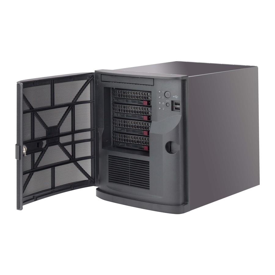
Chapter 4 System Interface Chapter 4 System Interface Overview The SC721 chassis includes a control panel which is located on the front of the chassis, behind the front bezel. that houses power buttons and status monitoring lights. These elements are described in this chapter with possible responses. Power Button Ports... -
Page 34: Control Panel Buttons
SC721 Chassis Manual Control Panel Buttons Power: The main power switch is used to apply or remove power from the power supply to the server system. Turning off system power with this button removes the main power but keeps standby power supplied to the system. Therefore, you must unplug system before performing most maintenance tasks. -
Page 35: Overheating
Chapter 4 System Interface Information LED: Alerts operator of several states, as noted in the table below. Informational LED Status Description An overheat condition has occured. Solid red (This may be caused by cable congestion). Fan failure, check for an inoperative fan. Blinking red (1Hz) Power failure, check for a non-operational Blinking red (0.25Hz) - Page 36 SC721 Chassis Manual Notes...
-
Page 37: Chapter 5 Chassis Setup And Maintenance
Chapter 5: Chassis Setup and Maintenance Chapter 5 Chassis Setup and Maintenance Overview This chapter covers the steps required to install components and perform main- tenance on the chassis. Most components of the SC721 do not require tools or screws to set them up. Those components which must be secured with screws require only a Phillips screwdriver. -
Page 38: Removing The Chassis Cover
SC721 Chassis Manual Removing the Chassis Cover Figure 5-1. Removing the Chassis Cover Removing the Chassis Side Cover 1. Power down the system and unplug the power cord from the power supply as described in Section 5-2. 2. Insert the key into the lock on the front bezel, turn the key counterclockwise and open up the front bezel. -
Page 39: Removing And Installing Hard Drives
Chapter 5: Chassis Setup and Maintenance Removing and Installing Hard Drives Figure 5-2. Removing the Hard Drive Carrier from the Hard Drive Chassis The SC721 chassis supports four 3.5" hot-swappable hard drives in hard drive carriers. These hard drives can be removed from the chassis without powering down the system. - Page 40 SC721 Chassis Manual Hard Drive Dummy Drive Hard Drive Carrier Figure 5-3. Installing a Hard Drive into Hard Drive Carrier Installing a Hard Drive into the Hard Drive Carrier 1. Remove the six screws which secure the dummy drive into the hard drive carrier.
- Page 41 Chapter 5: Chassis Setup and Maintenance Figure 5-4. Installing the Hard Drive Carrier into the Hard Drive Cage Installing 3.5" Hot-Swap Hard Drives 1. Insert the new hard drive into the hard drive carrier. 2. Insert the hard drive carrier into the hard drive cage, sliding it towards the back of the the hard drive cage until it clicks into a locked position.
-
Page 42: Installing The Internal Fixed Hard Drives
SC721 Chassis Manual Installing the Internal Fixed Hard Drives The SC721 supports two internal 2.5" SATA fixed hard drives, one top mounted drive and one side mounted drive. Figure 5-5. Installing the Top Mounted Fixed Hard Drive Installing the Top Mounted Fixed Hard Drive 1. -
Page 43: Installing The Side Mounted Fixed Hard Drive
Chapter 5: Chassis Setup and Maintenance Installing the Side Mounted Fixed Hard Drive Figure 5-6. Installing the Side Mounted Fixed Hard Drive Installing the Side Mounted Fixed Hard Drive 1. Power down the system and plug the power cord into the rear of the power supply as described in Section 5-2 and remove the chassis cover as de- scribed in Section 5-3. -
Page 44: Installing The I/O Shield And Motherboard
SC721 Chassis Manual Installing the I/O Shield and Motherboard The SC721 supports a wide range of Mini-ITX motherboards, which are sold sepa- rately and come with an I/O shield specific to the motherboard. The motherboard and the I/O shield are housed in a removable tray, located on the rear of the chassis. Figure 5-7. - Page 45 Chapter 5: Chassis Setup and Maintenance Installing the Motherboard and I/O Shield 1. With the illustrations facing the outside of the chassis, insert the motherboard ports through the openings in the I/O shield. 2. Slide the I/O shield into the opening in the rear of the chassis. 3.
-
Page 46: Hardware Security
SC721 Chassis Manual Hardware Security The SC721 features multiple locking devices to help deter hardware theft and pro- tect user data. While no lock is infalable, it is recommended that users keep their systems locked when not in use. Front Bezel Lock The SC721 has a locking front bezel to protect against unauthorized removal of the hard drives. -
Page 47: Kensington Cable Slot (K-Slot)
Chapter 5: Chassis Setup and Maintenance Kensington Cable Slot (K-Slot) The SC721 chassis features a Kensington cable slot or K-slot. This slot accepts a standard Kensington cable locking device (not included), Attach the loop end of the cable to a secure object, then insert the device into the K-slot as illustrated below. Figure 5-12. -
Page 48: Installing The Dvd-Rom Drive
SC721 Chassis Manual Installing the DVD-ROM Drive The SC721 chassis supports one DVD-ROM drive. Figure 5-13. Configuring the Chassis for the DVD-ROM Drive Installing the DVD-ROM Drive 1. Power down the system and remove the power cord from the rear of the power supply as described in Section 5-2 and remove the chassis cover as described in Section 5-3. - Page 49 Chapter 5: Chassis Setup and Maintenance Secure the DVD-ROM Drive with Screws (Optional) Figure 5-15. Installing the DVD-ROM Drive 6. Slide the DVD-ROM drive into the chassis. 7. If desired, secure the DVD-ROM drive with two screws as illustrated above. 8.
-
Page 50: 5-10 Installing Expansion Cards
SC721 Chassis Manual 5-10 Installing Expansion Cards The SC721 chassis includes one PCI slot for an expansion card. Figure 5-16. Installing the Expansion Card Installing the Expansion Card 1. Power down the system and remove the power cord from the rear of the power supply as described in Section 5-2 and remove the chassis cover as described in Section 5-3. -
Page 51: 5-11 Installing The Rear Exhaust Fan
Chapter 5: Chassis Setup and Maintenance 5-11 Installing the Rear Exhaust Fan Figure 5-17. Installing the Exhaust Fan The SC721 includes a 12 cm rear exhaust fan that provides cooling for the chassis. The chassis features a set of mounting holes which will support a standard 9 cm exhaust fan (fan not included). -
Page 52: 5-12 Replacing The Power Supply
SC721 Chassis Manual 5-12 Replacing the Power Supply The SC721 chassis includes a 250 Watt power fixed supply. In the unlikely event that it becomes necessary to replace the power supply, follow the instructions below. Power Supply Figure 5-18. Removing the Power Supply Changing the Power Supply 1. -
Page 53: 5-13 Replacing The Backplane
Chapter 5: Chassis Setup and Maintenance 5-13 Replacing the Backplane The SC721 chassis includes a BPN-SAS-733TQ backplane. In the unlikely event that it becomes necessary to replace the backplane, follow the instructions below. Detailed information on backplane settings are provided in Appendix C BPN-SAS- 733TQ Backplane Specifications in the back of this manual. - Page 54 SC721 Chassis Manual Notes 5-18...
-
Page 55: Appendix A Cables, Screws, And Other Accessories
This appendix lists the supported cables for the SC721 chassis. It only includes the most commonly used components and configurations. For more compatible cables, refer to the manufacturer of the motherboard and our Web site at www. supermicro.com. A-2 Cables Included with SC721 Chassis SC721TQ-250B Part # Type Quantity Description... -
Page 56: Hard Drive
SC721 Chassis Manual A-3 Chassis Screws The accessory box includes all the screws needed to set up your chassis. This section lists and describes the most commonly used screws. Your chassis may not require all of the parts listed. HARD DRIVE Flat head Pan head 6-32 x 5 mm... -
Page 57: Appendix B Sc721 Power Supply Specifications
Appendix B SC721 Power Supply Specifications This appendix lists power supply specifications for your chassis system. The SC721 chassis includes a power supply rated at 80 Plus Bronze Level. SC721TQ-250B 250W MFR Part # PWS-251-1H AC Voltage 100 - 240V, 50 - 60Hz, 5 Amp +5V Max:14 Amp;... - Page 58 SC721 Chassis Manual Notes...
-
Page 59: Appendix C Bpn-Sas-733Tq Backplane Specifications
Appendix C: BPN-SAS-733TQ Backplane Specifications Appendix C BPN-SAS-733TQ Backplane Specifications C-1 Safety Guidelines To avoid personal injury and property damage, please carefully follow all the safety steps listed below when accessing your system or handling the components: ESD Safety Guidelines Electrostatic Discharge (ESD) can damage electronic com ponents. - Page 60 This manual reflects BPN-SAS-733TQ Revision 3.00, the most current release avail- able at the time of publication. Always refer to the Supermicro Web site at www.su- permicro.com for the latest updates, compatible parts and supported configurations.
- Page 61 Appendix C: BPN-SAS-733TQ Backplane Specifications • Drive activity and drive failure indication for each drive slot. • Overheat/drive failure alarm via a buzzer* installed on the backplane. • A built in overheat/drive failure LED Indicator built in • Temperature monitoring via a two wire (I C) temperature sensor in the MG 9071 chip *The buzzer sound indicates that a condition requiring immediate attention has...
-
Page 62: Front Connectors
SC721 Chassis Manual C-4 Jumper Settings and Pin Definitions COM PONENT SI DE LAYER 1 Front Jumper/Connector Locations TOP SI LK SCREEN JP13 JP10 OH/DRI VE FAI L JP33: CTRL_I D R221 FAN FAI L R269 1- 2: SGPI O R210 2- 3: I 2C R149... - Page 63 Appendix C: BPN-SAS-733TQ Backplane Specifications C-5 Front Connector Pin Definitions Backplane Main Power Connectors (JP10, JP13) Pin Definitions Backplane Main Power Sideband Header - JP51 4-Pin Connectors (JP10, JP13) You must use the 4-pin power con- Pin Number Definition nectors JP10 and JP13 to provide adequate power to the backplane.
- Page 64 SC721 Chassis Manual 4. Front Panel Jumper Settings and Pin Definitions Front LED State Specification Overheat, drive failure or fan failure Fan failure only 5. Fan Enable/Disable Jumper Description Definition Open (Default) Normal JP18 Closed Buzzer reset JP26 Open (Default) Act #0 - 3 In Open (Default) Normal...
-
Page 65: Rear Connectors
Appendix C: BPN-SAS-733TQ Backplane Specifications C-6 Rear Connectors and LED Indicators Rear connector and LED locations SAS#3 SAS#2 SAS#1 SAS#0 Figure C-2: Rear View Rear Connectors Rear Connector Specification J1 (Rear) SAS#0 HDD (Connected to HDD) J2 (Rear) SAS#1 HDD (Connected to HDD) J3 (Rear) SAS#2 HDD (Connected to HDD) J4 (Rear) -
Page 66: Rear Connectors And Led Indicators
SC721 Chassis Manual Rear Connectors and LED Indicators Rear LED Indicators Specification D12 (Rear) SAS#0 Activity LED D13 (Rear) SAS#1 Activity LED D14 (Rear) SAS#2 Activity LED D15 (Rear) SAS#3 Activity LED D5 (Rear) SAS#0 Fail LED D6 (Rear) SAS#1 Fail LED D7 (Rear) SAS#2 Fail LED D8 (Rear) - Page 67 Appendix C: BPN-SAS-733TQ Backplane Specifications Notes...
- Page 68 SC721 Chassis Manual Disclaimer (cont.) The products sold by Supermicro are not intended for and will not be used in life sup- port systems, medical equipment, nuclear facilities or systems, aircraft, aircraft devices, aircraft/emergency communication devices or other critical systems whose failure to per- form be reasonably expected to result in significant injury or loss of life or catastrophic property damage.
Need help?
Do you have a question about the SC721TQ-250B and is the answer not in the manual?
Questions and answers