
Related Manuals for TFortis PSW-2G8F+Hot


Summary of Contents for TFortis PSW-2G8F+Hot
- Page 1 Multifunction Gigabit Managed Switch with PoE+ support (IEEE802.3at) up to 30 W per port for connecting eight IP video cameras designed to be used in hot climate PSW-2G8F+Hot Operating Manual Version 1...
- Page 2 Warning! Power supply elements are under high voltage. It is strictly forbidden to touch conducting elements of the power supply unit under voltage. SFP port operates only at 1000 Mbps. Fast Ethernet SFP modules will not operate. To ensure proper operation of lightning protection: •...
-
Page 3: Table Of Contents
Contents 1 Purpose ..........................4 2 Features ..........................4 3 Description ........................6 3.1 Enclosure ........................6 3.2 Optical distribution frame ....................8 3.3 Power supply unit ..........Ошибка! Закладка не определена. 3.4 Switch board ........................9 3.4.1 PoE jumpers ......................11 3.4.2 CPU button ...................... -
Page 4: Purpose
1 Purpose PSW-2G8F+Hot device is a multifunction gigabit outdoor managed switch designed for building IP video surveillance networks in hot climate. PSW-2G8F+Hot connection scheme (8 cameras) 2 Features Operation in extreme temperatures The switch is built based on industrial hardware with a wide range of operating temperatures. - Page 5 enclosure has a shield to reflect sunlight. Application of industrial SFP modules ensures operation in the temperature range from –40°C to +75°C. All-weather design The aluminum enclosure has dust and moisture protection rating IP67. All cables are pulled into the switch enclosure through a cable gland. High performance gigabit switch The key element of the switch is a high-performance chip from Marvell, which is able to process large amounts of traffic coming from the IP video cameras.
-
Page 6: Description
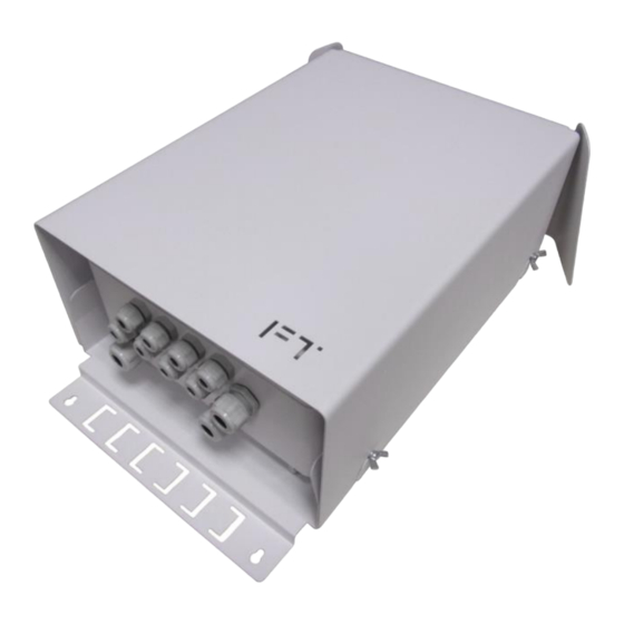
The optical distribution frame allows for optical cable splicing inside the switch and connecting it to SFP modules. Automatic circuit breaker The automatic circuit breaker allows to de-energize the switch during configuring and debugging. 3 Description 3.1 Enclosure External view View with the shield removed Figure 3.1.1 PSW-2G8F+Hot switch... - Page 7 Figure 3.1.2 PSW-2G8F+Hot interior Features of the switch enclosure • The aluminum enclosure is compact and has dust and moisture protection rating IP67. • The switch has a shield which reflects solar energy and prevents the device from overheating. • Vents provide air circulation between the shield and the enclosure for additional cooling of the switch.
-
Page 8: Optical Distribution Frame
Figure 3.1.3 Switch operation in hot climate 3.2 Optical distribution frame IMPORTANT! Nylon ties, shrinkable plastic sleeves, pigtails and adapters are not included in the scope of supply. -
Page 9: Power Supply Unit
Figure 3.2.1 Optical distribution frame 3.3 Power supply unit The power supply unit is located under the switch board. Access to the power supply unit is limited. The power supply unit has an aluminum radiator that is pressed against the back panel of the switch to remove the heat to the switch enclosure. - Page 10 Figure 3.4.1 Switch board Figure 3.4.2 Layout of components on the switch board...
-
Page 11: Poe Jumpers
3.4.1 PoE jumpers Ports of PSW-2G8F+Hot support PoE/PoE+ (IEEE802.3af/at) power supply of up to 30 W. Selection of power supply options is specified by the jumper configuration (Table 3.4.1). Table 3.4.1 Configuration of PoE jumpers Position Power supply option 1, 2 and 3, 6... -
Page 12: Default Button
3.4.3 DEFAULT button To restore factory settings, press the DEFAULT button and hold it down for about 15 seconds. The DEFAULT indicator should set ON at this point. 3.4.4 CPU indicator During normal processor operation, the CPU indicator should blink in 2-second intervals (1 second ON, 1 second OFF) 3.4.5 DEFAULT indicator DEFAULT indicator is ON when the device has the factory settings (IP... - Page 13 Figure 3.5.1 Tamper sensor on the switch board Figure 3.5.2 Tamper sensor curtain on the power supply unit cover IMPORTANT! Make sure you place the power supply unit cover correctly when closing it. The shutter shall fall between the tamper sensor ends.
-
Page 14: Lightning Protection Modules
3.6 Lightning protection modules PSW-2G8F+Hot switch has built-in lightning protection modules that protect Ethernet ports and 230 VAC power circuits from common-mode and differential electromagnetic interferences. The switches are resistant to powerful microsecond pulse interferences according to GOST R 51317.4.5 as per Table 3.7.1 with performance criteria B (temporary disruption of performance or functioning with further recovery without operator's intervention). -
Page 15: Automatic Circuit Breaker
Figure 3.7 Automatic circuit breaker 3.8 Additional functions 3.8.1 Restarting cameras in case of hanging PSW-2G8F+Hot continuously monitors the camera connection to the switch. There are three ways to detect camera hanging: • No connection to the camera (Link) • No response to service requests (Ping) •... -
Page 16: Cable Tester
camera. The Auto Restart option is available via the Web interface in the Special Function section (see the Configuration Manual). Camera restart due to no response to Ping request The switch constantly (1 time per minute) polls the IP camera. If the switch does not receive a response, then a one-minute timer is started, during this time the poll is repeated every 10 seconds. -
Page 17: Technical Specifications
4 Technical specifications Gigabit Ethernet ports • 1000Base-X with SFP connector; • Number of ports – 2; Fast Ethernet ports • 10/100Base-Tx with RJ-45 connector; • number of ports – 4; • Auto-MDIX support for 10/100Base-Tx port; • IEEE 802.3x flow control support; •... -
Page 18: Preliminary Setting
6 Preliminary setting 6.1 Resetting the switch to factory settings Before start, set the switch to default settings. To do this, press and hold the DEFAULT button until the DEFAULT indicator is ON. The default IP address of the switch is 192.168.0.1. 6.2 IP address setting All software functions of the switch can be managed, configured and monitored using the built-in WEB interface and Telnet. -
Page 19: Setting Poe On Ports
Figure 6.3 Entering user name and password. IMPORTANT! Note that the user name and password are case sensitive. 6.4 Setting PoE on ports Power supply via PoE is configured with the use of jumpers (see Section 3.4.2). All connections shall be performed with 230 VAC power off. 6.5 Activation of redundancy protocols If you connect the switches into a ring, then you need to enable the RSTP protocol. -
Page 20: Installation Of The Cabinet On Lamp Posts
IMPORTANT! Drilling of the enclosure will lead to loss of the switch integrity and result in the loss of product warranty. 7.2 Installation of the cabinet on lamp posts To install the cabinet on the lamp post, use TFortis Attachment Set (pole mount kit KKC-Hot), see the KKC-Hot Operating Manual. -
Page 21: Optical Connections
Figure 7.2 After installing the cabinet attach the top shield. IMPORTANT! ККС-Hot is not included in the scope of supply 7.3 Optical connections The switch has an optical distribution frame. For ease of operation, the optical distribution frame can be removed from the cabinet. The optical cable is pulled into PG13.5 cable glands. -
Page 22: Camera Connection
Figure 7.4 Connection scheme IMPORTANT! Grounding of the switch is mandatory. Grounding resistance should not exceed 4 Ohm. 7.5 Camera connection Camera connection recommendations: 1. use a 4-pair shielded twisted pair, at least category 5 2. use shielded RJ45 connections 3. -
Page 23: Manufacturer's Warranty
Figure 7.5 Standard cable separation. 8 Manufacturer's warranty The warranty period for the switch is 3 years from the date of sale. Only a complete switch is accepted for servicing and repair. Warranty shall not apply in the following cases: •... -
Page 24: Technical Support
To get technical support for the design of video surveillance systems, operation and adjustment of equipment: • call (8 a.m. to 4 p.m. Moscow time) +7 342 270 112 8 +7 342 260-20-30 • send an e-mail to: tfortis@fort-telecom.ru All technical documentation is available at: https://tfortis.com/support/dokumentaciya-na-produkciyu/...
Need help?
Do you have a question about the PSW-2G8F+Hot and is the answer not in the manual?
Questions and answers