
Related Manuals for TFortis PSW-2G+Hot


Summary of Contents for TFortis PSW-2G+Hot
- Page 1 Multifunction Gigabit Managed Switch with PoE+ support (IEEE802.3at) up to 60 W per port for connecting four IP video cameras, designed to be used in hot climate PSW-2G+Hot Operating Manual Version 1...
- Page 2 Warning! Power supply elements are under high voltage. It is strictly forbidden to touch conducting elements of the power supply unit under voltage. SFP port operates only at 1000 Mbps. Fast Ethernet SFP modules will not operate. To ensure proper operation of lightning protection: •...
-
Page 3: Table Of Contents
Contents 1 Purpose ..........................4 2 Features ..........................5 3 Description ........................7 3.1 Enclosure ........................7 3.2 Optical distribution frame ....................9 3.3 Power supply unit ......................9 3.4 Switch board ........................ 10 3.4.1 CPU button ......................11 3.4.2 DEFAULT button ....................11 3.4.3 CPU indicator ....................... -
Page 4: Purpose
1 Purpose PSW-2G+Hot device is a multifunction gigabit outdoor managed switch designed for the construction of IP video surveillance networks. PSW-2G+Hot connection scheme... -
Page 5: Features
2 Features Operation in extreme temperatures The switch is built based on industrial hardware with a wide range of operating temperatures. All heat-generating components of the switch are provided with heat removal to the switch enclosure. The enclosure acts as a radiator. The enclosure has a shield to reflect sunlight. - Page 6 Cameras restart automatically in case of hanging The switch controls operation of the camera. In case of hanging, the switch will restart the camera automatically over PoE. It allows to build unattended IP video surveillance systems. Operation in a ring or a chain configuration Two gigabit ports allow to connect switches in a chain.
-
Page 7: Description
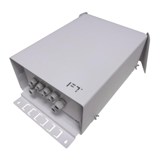
3 Description 3.1 Enclosure External view View with the shield removed Figure 3.1.1 PSW-2G+Hot switch Figure 3.1.2 PSW-2G+Hot interior... - Page 8 Features of the switch enclosure • The aluminum enclosure is compact and has dust and moisture protection rating IP67. • Vents provide air circulation between the shield and the enclosure for additional cooling of the switch. • The shield is attached to the enclosure at several points to eliminate heat passage from the external casing into the switch.
-
Page 9: Optical Distribution Frame
3.2 Optical distribution frame IMPORTANT! The scope of supply does NOT include nylon ties, shrinkable plastic sleeves, pigtails and adapters. Figure 3.2.1 Optical distribution frame 3.3 Power supply unit The power supply unit is located under the switch board. Access to the power supply unit is limited. -
Page 10: Switch Board
Figure 3.3 Power supply unit 3.4 Switch board The switch board is mounted on an aluminum plate that removes the heat from hot electronic components to the switch enclosure. Figure 3.4.1 Switch board... -
Page 11: Cpu Button
Figure 3.4.2 Layout of components on the switch board 3.4.1 CPU button To restart the switch, short press the CPU button. 3.4.2 DEFAULT button To restore factory settings, press the DEFAULT button and hold it down for about 15 seconds. The DEFAULT indicator should set ON at this point. 3.4.3 CPU indicator During normal processor operation, the CPU indicator should blink in 2-second intervals (1 second ON, 1 second OFF) -
Page 12: Poe Indicators
3.4.5 PoE indicators The PoE A indicator is ON when power is supplied over data (pairs 1, 2 and 3, 6). The PoE B indicator is ON when power is supplied via free pairs (pairs 4, 5 and 7, 8). 3.4.6 LINK indicators A blinking LINK indicator shows that data are transmitted via the corresponding port. -
Page 13: Lightning Protection Modules
IMPORTANT! Make sure you place the power supply unit cover correctly when closing it. The shutter shall fall between the tamper sensor ends. 3.6 Lightning protection modules PSW-2G+Hot switch has built-in lightning protection modules that protect Ethernet ports and 230 VAC power circuits from common-mode and differential electromagnetic interferences. -
Page 14: Automatic Circuit Breaker
4 kV 2 kV IMPORTANT! Grounding of the switch is mandatory for lightning protection. 3.7 Automatic circuit breaker The switch is provided with an automatic circuit breaker for ease of maintenance. Figure 3.7 Automatic circuit breaker... -
Page 15: Additional Functions
3.8 Additional functions 3.8.1 Restarting cameras in case of hanging PSW-2G+Hot continuously monitors connection of the camera to the switch. There are three ways to detect camera hanging: • No connection to the camera (Link) • No response to service requests (Ping) •... -
Page 16: Cable Tester
restore, the switch decides that the camera is hanging and restarts it. The user may specify the limit values (see the Configuration Manual). 3.8.2 Cable tester The switch can function as a virtual cable tester (VCT), which allows to determine the breakage of the twisted pair, short-circuiting of the twisted pair wires, cable disconnection from the camera, distance from the switch to the fault. -
Page 17: Operating Conditions
• Maximum power consumption – 200 W. Design • dimensions – 459х247х175 mm • maximum weight – 11 kg • environmental protection rating IP67 • cable glands – 4-8 mm cable – 8 pcs. – 6-12 mm cable – 3 pcs. Reliability •... -
Page 18: User Name And Password Setting
Connect any switch port to an Ethernet network. Note that if the device is configured over a network, the IP address of the management workstation should belong to the same IP network. For example, if the default IP address of the switch is 192.168.0.1, then the IP address of the workstation should be 192.168.0.x (where x is a number from 2 to 254);... -
Page 19: Installation Of The Switch
7 Installation of the switch 7.1 Installation of the cabinet on the wall The cabinet has four attachment points. Marking of the attachment points is shown in Figure 7.1. Figure 7.1 Marking of attachment points IMPORTANT! Drilling of the enclosure will lead to loss of the switch integrity and result in the loss of product warranty. -
Page 20: Installation Of The Cabinet On Lamp Posts
7.2 Installation of the cabinet on lamp posts To install the cabinet on the lamp post, use TFortis Attachment Set (pole mount kit KKC-Hot), see the KKC-Hot Operating Manual. Figure 7.2 After installing the cabinet attach the top shield. IMPORTANT! KKC-Hot is not included in the scope of supply 7.3 Optical connections... -
Page 21: Power Supply Connection
7.4 Power supply connection The switch is connected to 230VAC source. Power supply cable is pulled into the power supply unit through PG13.5 cable gland and is connected to the automatic circuit breaker. The grounding wire is connected to a special grounding screw. -
Page 22: Manufacturer's Warranty
3. use minimum length of cables coming to video cameras 4. avoid parallel installation of twisted pair and power cables Figure 7.5 Standard cable separation 8 Manufacturer's warranty The warranty period for the switch is 3 years from the date of sale. Only a complete switch is accepted for servicing and repair. -
Page 23: Technical Support
To get technical support for the design of video surveillance systems, operation and adjustment of equipment: • call (8 a.m. to 4 p.m. Moscow time) +7 342 270 112 8 +7 (342) 260-20-30 • send an e-mail to: tfortis@fort-telecom.ru All technical documentation is available at: https://tfortis.com/support/dokumentaciya-na-produkciyu/...
Need help?
Do you have a question about the PSW-2G+Hot and is the answer not in the manual?
Questions and answers