
Related Manuals for TFortis PSW-2G4F-Box


Summary of Contents for TFortis PSW-2G4F-Box
- Page 1 Multifunction Gigabit Managed Switch with PoE support (IEEE802.3af) for IP Video Surveillance Systems PSW-2G4F-Box Operating Manual Version 1...
- Page 2 Warning! Power supply elements are under high voltage. It is strictly forbidden to touch conducting elements of the power supply unit under voltage. When connecting a computer to the switch, remove PoE jumpers for this port. SFP port operates only at 1000 Mbps. Fast Ethernet SFP modules will not operate.
-
Page 3: Table Of Contents
Table of contents 1 Purpose ..........................4 2 Features ..........................5 3 Description ........................7 3.1 Appearance ........................7 3.2 Cabinet .......................... 8 3.3 Optical distribution frame ....................8 3.4 Switch board and power supply units ................9 3.4.1 PoE jumpers ......................10 3.4.2 230VAC power supply backup jumpers .............. -
Page 4: Purpose
1 Purpose PSW-2G4F-Box is a multifunction gigabit outdoor managed switch used for the construction of IP video surveillance networks. Figure 1 - PSW-2G4F-Box connection scheme... -
Page 5: Features
The switch may supply PoE to any camera compliant with IEEE802.3af standard. Power supply of camera housings via PoE During operation with TFortis TH camera housings the switch uses a standard twisted pair to power both the camera (IEEE802.3af) and the camera housing (Passive PoE). - Page 6 Cold start For safe and guaranteed start of video cameras in freezing weather, TFortis TH equipment allows for preheating of camera housings. Automatic cameras restart in case of hanging The switch controls operation of the camera. In case of hanging, the switch will reboot the camera automatically over PoE.
-
Page 7: Description
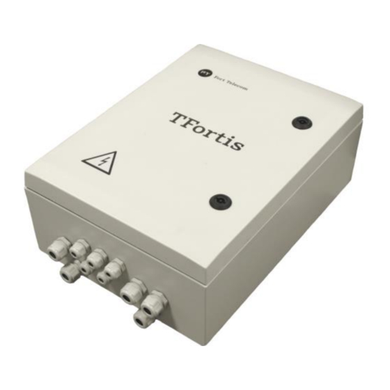
3 Description 3.1 Appearance Figure 3.1.1 - PSW-2G4F-Box - external appearance Figure 3.1.2 - PSW-2G4F-Box - interior... -
Page 8: Cabinet
3.2 Cabinet Cabinet features 100% corrosion protection due to glass-filled polycarbonate IK10 impact protection rating due to fiber glass reinforcement Dust and moisture protection rating – IP66. Fire resistance – UL94-5VA Electrical insulation – 1500VDC ... -
Page 9: Switch Board And Power Supply Units
3.4 Switch board and power supply units Figure 3.4.1 - Switch board and power supply units... -
Page 10: Poe Jumpers
Figure 3.4.2 - Layout of components inside PSW -2G4F-Box 3.4.1 PoE jumpers PSW-2G4F-Box switch supports IEEE802.3af and Passive PoE power supply. Selection of power supply options is specified by the jumper configuration (Table 3.4.1). Power is supplied via pairs 1, 2 and 3, 6 over data (Option A) or by free pairs 4, 5 and 7, 8 (Option B). - Page 11 IEEE802.3af (video camera) IEEE802.3af (video camera) IMPORTANT! When using TFortis TH (I) camera housings put RES_PWR jumper into the NO position (see Section 3.4.2).
- Page 12 Figure 3.4.3 - Power supply scheme over PoE for different variants.
-
Page 13: 230Vac Power Supply Backup Jumpers
3.4.2 230VAC power supply backup jumpers PSW-2G4F-Box switches have two power supply units. The left PSU is designed to supply power to the switch and video cameras over PoE. The right PSU has two operating modes selected by RES_PWR jumper according to Table 3.4.2. -
Page 14: Poe Indicators
3.4.7 PoE indicators The PoE A indicator is ON when power is supplied over data (pairs 1, 2 and 3, 6). The PoE B indicator is ON when power is supplied by free pairs (pairs 4, 5 and 7, 8). 3.4.8 LINK indicators Blinking of LINK indicators show that data are transmitted via the corresponding port. - Page 15 alarm message to be sent to the server via SNMP Traps, SMTP or Syslog protocols (see detailed information in the Configuration Manual). Figure 3.6.1 - Tamper sensor on the switch cover Figure 3.6.2 - Tamper sensor on the switch enclosure...
-
Page 16: Integrated Lightning Protection
3.7 Integrated lightning protection PSW-2G4F-Box switch has built-in lightning protection modules that protect Ethernet ports and ~230VAC power circuits from common-mode and differential electromagnetic interferences. The switches are resistant to powerful microsecond pulse interferences according to GOST R 51317.4.5 standard as per Table 3.7.1 with performance criteria B (temporary disruption of performance or functioning with further recovery without operator's intervention). -
Page 17: Automatic Circuit Breaker
3.10.1 Cold start The most critical moment in camera operation is its start at low temperature. Cold start may result in failure of an expensive camera. To prevent that, TFortis TH camera housings of PSW-2G4F-Box switch have a preliminary heating function. -
Page 18: Cable Tester
Video camera restart using Link signal The switch continuously (once a minute) monitors the Link signal from the IP camera. If the switch fails to detect the Link signal, then a one-minute timer is started, and after that the connection is monitored again. If the Link signal does not appear, the switch removes power for 10 seconds and supplies it again, rebooting the camera. -
Page 19: Remote Camera Polling
By default, VCT operates on an average algorithm and does not take into account the specific features of a particular cable, which can affect the accuracy of the measurement. To improve the accuracy of the cable tester, it is recommended to calibrate it. Note that calibration is not recommended for cables shorter than 10 meters. -
Page 20: Operating Conditions
– 6-12 mm cable – 5 pcs. Reliability meantime between failures at least 75 000 hours (8.6 years). 5 Operating conditions The switch is designed for 24-hour operation in outdoor conditions at an ambient temperature from minus 60 to plus 55 C* and above up to +70 C* with the use of industrial SFP modules. -
Page 21: Preliminary Setting
6 Preliminary setting 6.1 Resetting the switch to factory settings Before start, set the switch to the default settings. To do this, press and hold the DEFAULT button until the DEFAULT indicator lights up. The default IP address of the switch is 192.168.0.1. 6.2 IP address setting All software functions of the switch can be managed, configured and monitored using the built-in web interface and Telnet. -
Page 22: Setting Poe On Ports
To solve this problem, use the Comfort Start function. To do this, go to the Comfort Start section on the Special Function tab and enable the option. By default, it is OFF. The function is available only with TFortis TH camera housings. -
Page 23: Activation Of Redundancy Protocols
When this option is enabled after power supply to the switch, the cameras will start in Soft Start Time. For forced camera start, press Manual Start. 6.6 Activation of redundancy protocols If you connect the switches into a ring, then you need to enable the RSTP protocol. -
Page 24: Installation Of The Cabinet On Lamp Posts
Drilling of the housing will lead of loss of the switch integrity and, as a result, loss of product warranty. 7.1 Installation of the cabinet on poles To mount the cabinet on the pole, use TFortis-1 Attachment Set for square and round posts. -
Page 25: Optical Connections
Figure 7.2 - TFortis-1 Attachment Set. IMPORTANT! The Attachment Set is not included in the supply scope. 7.3 Optical connections The switch has an optical distribution frame. For ease of operation the optical distribution frame can be removed from the cabinet. The optical cable is pulled into PG13.5 cable glands. -
Page 26: Power Supply Connection
7.4 Power supply connection The switch is connected to 230VAC source. Power supply cable is pulled into the unit through PG13,5 cable gland and is connected to the power supply terminal blocks. Figure 7.4.1 - Connection of switches in a chain... -
Page 27: Camera Connection
Figure 7.4.2 - Connection from various power supply sources For ease of maintenance the automatic circuit breaker is included in the scope of supply. IMPORTANT! Grounding of the switch is mandatory. Grounding resistant should not exceed 4 Ohm. 7.5 Camera connection Camera connection recommendations: 1. -
Page 28: Manufacturer's Warranty
To get technical support for the design of video surveillance systems, operation and adjustment of equipment: Email at tfortis@fort-telecom.ru All technical documents are available at: https://tfortis.com/support/dokumentaciya-na-produkciyu/ Schedule Power consumption calculation Power consumption of TFortis PSW switch is calculated by the following formula... - Page 29 Example It is required to calculate power consumption of TFortis PSW-2G4F-Box switch with three AV1310 cameras with TFortis TH-02 camera housings connected to ...
- Page 30 Вт ...
Need help?
Do you have a question about the PSW-2G4F-Box and is the answer not in the manual?
Questions and answers