
Related Manuals for TFortis PSW-11


Summary of Contents for TFortis PSW-11
- Page 1 Operation Manual PSW-11 Multifunctional Gigabit Switch for IP- video surveillance systems Version 5...
- Page 2 Components of power supply units are under high voltage Touching conducting components of active power supply units is forbidden. When connecting the computer to the switch, remove PoE jumpers at this port. For effective operation of lightning protection is required: •...
-
Page 3: Table Of Contents
Table of Contents 1. Designation ..................... 4 2. Description ....................6 2.1. Appearance ..................6 2.2. Element arrangement ................. 7 2.3 Power supply over PoE ..............8 2.4 Optical port ..................10 2.5 Lightning protection ................10 2.6 Cold start ..................11 2.7 Restart of video cameras at their hanging ........ -
Page 4: Designation
1. Designation Device PSW-11- is a Multifunctional Gigabit Switch in street version designed for connection of one IP-camera by optics. This switch has two ports. First port is optical, the second - copper. The optical port is designed to connect it to other switches (media converters), the second - to connect the video camera. - Page 5 The switch can power any PoE-camera that supports IEEE802.3af standard. Power supply for Camera housings over PoE Switch operating with TFortis TH Camera housings powers both video camera (IEEE802.3af) and Camera housing (Passive PoE) via twisted pair. Connection to 220V Built-in PSU provides direct connection of the switch to the Power Supply 220V and excludes need in additional PSU.
-
Page 6: Description
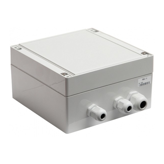
2. Description 2.1. Appearance Figure 2.1-1. PSW-11- outside view Figure 2.1-2. PSW-11 - inside view... -
Page 7: Element Arrangement
2.2. Element arrangement FIBER jumper 3.3V Indicator CPU Indicator 48V Indicator RESTART jumper PoE Jumpers TIMER jumper LINK indicators Fuse 250VAC, 3.15A Power socket 220VAC 100/1000Base-X (SFP) Grounding Screw 10/100Base-Tx with PoE Figure 2.2-1. Element arrangement of PSW -11 During normal operation, CPU indicator must light intermittently with a frequency of 2s. -
Page 8: Power Supply Over Poe
A and the second - mode B. Power is supplied to video cameras installed into TFortis TH camera housing using mode A and mode B simultaneously (I). When you connect other devices (not PoE), remove jumpers for relevant port (IV). - Page 9 Pairs 1,2 and 3,6 IEEE802.3af TFortis TH camera Pairs 4,5 and 7,8 housing Passive PoE Pairs 1,2 and 3,6 IEEE802.3af Pairs 4,5 and 7,8 Passive PoE Figure 2.3 Power supply scheme over PoE in different cases...
-
Page 10: Optical Port
2.4 Optical port The optical port of the switch is made in the form of a SFP slot, which operates at speeds of 100Mbps or 1000Mbps, depending on the position of the jumper FIBER. Table 2.4. Compatibility of SFP modules 100Base-X 1000Base-X Module 1.25Gbit/s... -
Page 11: Cold Start
To avoid such cases, the switch is implemented with preheating of TFortis TH camera housings. The essence of it is that after power is applied to the unit, initially will be powered heating elements of camera housings, and only then in 1 hour the video camera itself. -
Page 12: Restart Of Video Cameras At Their Hanging
2.7 Restart of video cameras at their hanging Switch constantly monitors the intensity of the traffic from the video camera. If the network activity is lost, the switch resets the camera by removing power through PoE. This feature is enabled by setting AUTO RESTART jumper to ON for a specific port. -
Page 13: Presetting
Moreover, after 1 hour, when comfortable conditions will be created in the camera housing, a video camera will be powered. By default, this function is disabled. IMPORTANT! This function is available only with TFortis TH camera housings. -
Page 14: Device Installation
IMPORTANT! Drilling of the housing leads to a violation of the sealing of the entire commutator and, as a consequence, the loss of warranty. 6.2. Optic connection There are no elements for welding of the optical fiber inside the PSW-11. It is recommended to use External Optical Distribution Frames. -
Page 15: Power Connection
6.3. Power connection PSW-11 is connected to an AC source of 220V. The supply cable is brought into the unit through the cable gland, where it is connected to the terminal block of the power supply unit. IMPORTANT! Grounding of the device is required. The ground resistance must be no more than 4 ohms. -
Page 16: Manufacturer's Warranty
7. Manufacturer’s warranty Warranty period for the device – 36 months from the sale date. The device is accepted for warranty maintenance and repair only in full completeness. Warranty repair is not performed in following cases: • if warranty period has expired; •...
Need help?
Do you have a question about the PSW-11 and is the answer not in the manual?
Questions and answers