Table of Contents
Advertisement
Quick Links
Operation Manual
Circulation-Type Liquid Cooler
ORION Unit Cooler
RKS250F-S
RKS400F-S
RKS500F
RKS750F
●This product is designed for industrial use. Handle with care.
●Please read this manual carefully and operate this product
accordingly.
●Retain this manual for future reference.
This manual is comprised of two sections.
Operation Guide .................................. Pages 1 - 35
Installation Guide ................................. Pages 36 - 57
03107377010
Advertisement
Chapters
Table of Contents

Related Manuals for Orion RKS250F-S


Summary of Contents for Orion RKS250F-S
- Page 1 Operation Manual Circulation-Type Liquid Cooler ORION Unit Cooler RKS250F-S RKS400F-S RKS500F RKS750F ●This product is designed for industrial use. Handle with care. ●Please read this manual carefully and operate this product accordingly. ●Retain this manual for future reference. This manual is comprised of two sections.
- Page 2 Thank you for your purchase. Thank you for purchasing this Orion product. To ensure safe and efficient use, please install and operate this product in accordance with the instructions provided in this manual. Safety Precautions Before operating this product, be sure to read through the "Essential Safety Precautions" presented in this manual.
-
Page 3: Table Of Contents
Operation Guide Contents Essential Safety Precautions ............1 To Maintain Efficient and Trouble-Free Performance ....3 Machine Layout ................6 Operating Procedures ..............8 Safety Devices ................15 Monitoring................... 16 Parameters ................. 17 Inspection and Maintenance ............. 22 Water Quality Management ............25 Troubleshooting ................. -
Page 4: Essential Safety Precautions
Essential Safety Precautions Usage Precautions WARNINGS Failure to observe the instructions contained in a WARNING may result in death or severe injury. Do not modify this product. Modification of this product will void the warranty. Do not attempt to carry out disassembly and repairs yourself. Disassembly and repair must be carried out by the dealer or by qualified service specialists. - Page 5 Essential Safety Precautions Usage Precautions CAUTIONS Failure to observe the instructions contained in a CAUTION may result in injury or physical damage. Do not feed incorrect liquid into the product. This product is designed to operate with fresh water (compliant with the water standards developed by the Japan Refrigeration and Air Conditioning Industry Association, see page 25) or with an ethylene-glycol water solution that has a concentration of 10% or lower.
-
Page 6: To Maintain Efficient And Trouble-Free Performance
Essential Safety Precautions Warning Label on Product Warning Label on the Product The warning labels shown below display important warnings, and the label on the front of the chiller displays particularly important warnings. Be sure to read these warnings before operating this product. If the labels become worn or damaged in any way, contact your dealer for a replacement. - Page 7 To Maintain Efficient and Trouble-Free Performance 3. Note the operating ranges and always operate the product within these ranges. Operating outside the specified ranges can damage the product. RKS250-F RKS400-F RKS500F RKS750F Working water temp. 5 ~ 25 (℃) range Ambient temp.
- Page 8 To Maintain Efficient and Trouble-Free Performance 9.Please Consult with your dealer if the product stops due to activation of an internal safety device. 10.The water level in the tank may drop due to long piping, or operation of the product for the first time. In such cases, stop the product, replenish the water, and restart the product.
-
Page 9: Machine Layout
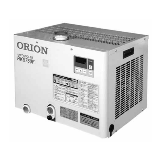
Machine Layout External Appearance External Appearance ■External View Pump-Priming port (Front) (Pump-priming port cap) Control Plate Water outlet Rp3/4 Power cord access hole (φ30) Drain port M10 (incl. grommet) Water inlet Rp3/4 (Drain plug) (Back) Condenser filter and condenser... - Page 10 Machine Layout Control plate ① ② ③ ⑥ ④ ⑤ Measured water temperature (normally displayed) ①Digital Display Alarm (error) code display (flashing) ②Cooler operation Lamp Operation/Stop of chiller. ③Cooler ON/OFF Switch Error/alarm reset or error buzzer stops. ④RESET Switch Press briefly・・・・・・・・・・・・・・Liquid temperature setting display. Hold down for 2 seconds・・・To the liquid temperature setting change mode.
-
Page 11: Operating Procedures
Operating Procedures If Starting Up For the First Time, or After Prolonged Period of Non-Use WARNING ● Never operate switches with wet hands, and never touch electrical components. Improper handling may result in electric shock. WARNING ● Never operate the product while the cabinet is open or removed. Touching the inside of the product may result in injury or electric shock. - Page 12 ■Checking the Water Level. Confirm there is water in the water tank. Add water to the water tank. The amount of water should be at least the amount of water shown in the following chart. RKS250F-S RKS400F-S RKS500F RKS750F Required water tank...
- Page 13 Operating Procedures Local operation Mode(Operation using the Control Plate) Local Operation Mode (Operation Using the Control plate) The product can be controlled locally if parameter "F2" is set to either "0" or "2". (The factory default setting is "2".) If parameter "F2" is changed, parameter "F1" will automatically be reset at the same time. Therefore, after changing "F2", check the value of "F1"...
- Page 14 Operating Procedures Local Operation Mode / Remote Operation mode ■ Circulation Pump Independent Operation 1.While pressing the temperature adjust switch ▲, press the cooler ON/OFF switch. The cooler operation lamp will flash, the digital display will show “ ”, and the circulation pump will be operating.
- Page 15 Operating Procedures Dual Mode (Operation in Combination of Local and Remote Modes) Dual Mode (Operation in Combination of Local and Remote Modes) If parameter “F2” is set to “2” (factory default setting), then the product can be operated as follows: ■ Starting The Product 1.When the remote switch is OFF (terminals 14 and 15 are open), and the product is not running :...
- Page 16 Operating Procedures Other Operations Other Operations ■ How to Confirm the Temperature Setting 1. Press the "SET" switch. The water temperature setting will show on the digital display for several seconds. ■ How to Clear an Alarm 1. Press the "RESET" switch. After removing the actual cause of the alarm, pressing the reset switch will clear the alarm.
- Page 17 Operating Procedures Other Other IMPORTANT ● If signal outputs are to be used, please ask your dealer or other qualified person to perform the required wiring and installation. ■ Operating Signal The signal will be output from when the product is turned on by pushing the ON/OFF switch, and will continue to be output until the ON/OFF switch is pushed again to stop the product.
-
Page 18: Safety Devices
Safety Devices Product State Corrective Name of safety Error Action when Function device Display safety device Compressor Pump activates Activates when the temperature of the gas discharged from the compressor becomes Motor protector E 01 excessively high due to overload. Cuts off the electrical circuit and stops operation of the entire product. -
Page 19: Monitoring
Monitoring Displaying Refrigerator State Displaying Refrigerator State This product can display operational data in the digital display on the control panel. 1. Hold down the SET switch on the control plate for 7 seconds to switch the temperature setting blinking on the digital display to alternate display of "Hr." and the "accumulated operating hours". 2. -
Page 20: Parameters
Parameters Setting and Changing Parameters Setting and Changing Parameters Various functions of the product can be selected by changing parameter settings. ■ Parameter Setting Overview Example: Display and change the “F5” parameter (Audible alarm enable/disable). (This example will show to change the audible alarm from the factory default setting of “1” to “0”.) Doing so switches to the parameter display mode. - Page 21 Parameters Parameter Types and Functions Parameter Types and Functions ■ Parameter List (Settings can be changed while the product is running, except for “F15”.) Parameter Setting Min. set Factory default Description Units Number range value setting Power-cutoff recovery setting 0 ~ 2 ―...
- Page 22 Parameters Parameter Types and Functions ● ”F2” Local / Remote operation priority select (relevant parameter “F1”) Selects the active ON / OFF switch (cooler ON / OFF switch) between the (local) control plate or remote control switch. “F2” set value Description “F1”...
- Page 23 Parameters Parameter Types and Functions ● "F20" Water temperature upper/lower limit warning enable (Relevant parameters: "F21", "F22", and "F23".) Set this parameter to detect abnormal water temperatures. Set specific detection temperatures in parameters "F21", "F22", and "F23". “F20” set value Description Alarm detect disabled Incl.
- Page 24 Parameters Parameter Types and Functions ● "F22" Water temperature upper/lower limit warning upper limit value (relevant parameters: "F20" and "F23"). Can be set if "F20" is set to "3" or "4". Regardless of the set water temperature, if the water temperature goes above this value, the alarm will be output.
-
Page 25: Inspection And Maintenance
Inspection and Maintenance Every Week WARNING ● Never operate switches with wet hands, and never touch electrical components. Improper handling may result in electric shock. WARNING ● Do not use water to clean this product, and do not allow water to spill onto or in the vicinity of this product. - Page 26 Inspection and Maintenance Bimonthly Inspection and Maintenance / Monthly Inspection and Maintenance Bimonthly Inspection and Maintenance 1. Inspection for drain port leakage ※ If water leakage is detected, check for scratches or breaks and consult with your dealer. Replace the drain gasket if it is scratched or deformed. 2.
- Page 27 Inspection and Maintenance Monthly Inspection and Maintenance / Every half year 4. Clearing a " " 500-hour Filter Use Caution Alarm After cleaning condenser and the filters, clear the operating-hour timer for " ". ● Clearing the " "500-hour Filter Use Caution Alarm operating-hour timer ①Hold down the RESET switch on the control plate for 5 seconds or longer.
-
Page 28: Water Quality Management
Water Quality Management CAUTION 1. Chilled water should be either clean water (tap water) or a 10% or weaker solution of industrial use ethylene glycol in water. Use of non-approved water can result in damage to the product, leaking, and possible electric shock or electrical shorts. - Page 29 Water Quality Management 3. Refer to the following chart in order to avert future trouble. Condition of working Description of trouble Procedures to take water working water ORION's water quality standards The presence of chloride ion or other corrosive chloride other designed...
- Page 30 Troubleshooting Troubleshooting Charts WARNING ● If the product behaves abnormally, switch it off and then cut the power. Then contact your dealer or product specialist. Continuing to run the product while operation is abnormal may result in fire or electric shock. CAUTION ● ...
-
Page 31: Troubleshooting
Troubleshooting Alarm Types and Product Response Chart Alarm Types and Product Response Chart ■Alarm list Actions in Alarm Operation Alarm Name response to Display Restore Number Signal Signal alarms Alternate 500-hour filter use caution alarm Running ○ × Manual displays Alternate Compressor motor protector All stopped... - Page 32 ・Please consult with your dealer if the problem persists after Other error pressing the RESET switch. ※1 RKS250F-S RKS400F-S RKS500F RKS750F Required water tank capacity (L) At least 10 At least 20...
- Page 33 Troubleshooting IMPORTANT ● If one of the built-in safety devices activates, press the RESET switch, conduct the appropriate measures as noted above, and then restart operation. (Please wait 3 minutes after the product stops before starting the product again.) ● Please consult with your dealer if a problem cannot be resolved by following the above mentioned measures.
- Page 34 Troubleshooting Place of fuse and reset switch with overcurrent relay Place of fuse and reset switch with overcurrent relay WARNING ● Be sure to remount the cabinet plate(s) after resetting safety devices or taking other corrective action. Never operate the product while the cabinet is open. Touching the inside of the product may result in injury or electric shock.
-
Page 35: Storing The Product
Storing the Product (Preparing for winter or for other extended period of non-use) 1. Switch OFF the breaker. Cut off the power source. (Switch off the power source breaker.) 2. Drain water from the pipes (including the main unit and the water tank.) (1) Drain the water from the water tank. -
Page 36: Expendable Parts
03091800010 Condenser filter (RKS500F) 03091749010 Condenser filter (RKS750F) 18502113040 For controller (125 V, 1 A RKS250F-S, 400F-S) Glass fuse ―― Fuse is blown 18502123040 For controller (250 V, 1 A RKS500F, 750F) ※1 Times represent rough indication values to be reviewed considering application conditions (including ambient temperature and environment surrounding the product). -
Page 37: Disposal
Maintenance intervals of the main parts ■Maintenance intervals of the main parts Approximate interval time when it becomes necessary to replace the parts depending on the using conditions. Part name Part number Piece/unit Replacement time Remarks 0A000453000 RKS250F-S 0A000908000 RKS400F-S Compressor 0A000922000 RKS500F 0A000385020 RKS750F... -
Page 38: After-Sale Services
■About functionality service components: ● Functionality service components are parts required for maintaining the product's functionality. ● Orion will maintain the functionality service components for this product for at least 7 years after its production termination. ■How to request after-sale services ●... - Page 39 Installation Guide Installation of this product should be performed by your dealer or other qualified personnel. Improper installation by the user could result in water leaks, electric shock, or fire. Contents Essential Safety Precautions ............ 37 Moving the Product to the Installation Site ......39 Installation ..................
-
Page 40: Essential Safety Precautions
Essential Safety Precautions Usage Precautions WARNINGS Failure to observe the instructions contained in a WARNING may result in death or severe injury. Be sure to install this product in accordance with the instructions given in this manual. Improper installation may lead to water leakage, electric shock, or fire. Installation should be carried out by your dealer or by a qualified installation engineer. - Page 41 Essential Safety Precautions Usage Precautions CAUTIONS Failure to observe the instructions contained in a CAUTION may result in injury or physical damage. Be sure that the installation site is sufficiently strong to bear the full weight of this product. The product must be installed so that it is level, and must be secured into place so that it cannot be accidentally overturned.
-
Page 42: Moving The Product To The Installation Site
Moving the Product to the Installation Site Initial Check / Moving the Product to the Installation Site Initial Check Upon receiving the product, check it carefully for signs of shipping-related damage (scratches, dents, etc.). If you notice a problem, please contact your dealer. Moving the Product to the Installation Site 1. - Page 43 If such measures are to be taken, ensure that such construction does not result in a drop in fan air flow. RKS250F-S RKS400F-S RKS500F RKS750F...
- Page 44 Piping Installation Piping Installation CAUTION ● Make sure that piping is installed reliably and correctly. Failure to do so can result in water splashing on nearby items. 1. Water piping. RKS250F-S RKS400F-S RKS500F RKS750F Water tank capacity (L) At least 10...
- Page 45 Installation Piping Installation IMPORTANT ● An alarm will be generated and the product will not operate if the inlet and outlet ports are reversed. ● Be careful during piping installation not to allow dirt or other foreign material to enter the water circuit, etc. ● Choose a PVC pipe or spring-protected hose to avoid kinks in the pump intake.
- Page 46 Installation Wiring Work Wiring Work WARNING ● Electrical work should be carried out in accordance with the instructions given in this manual, using dedicated circuitry only. Improper workmanship or insufficient electrical capacity may result in electric shock, fire, or other hazard. ●...
- Page 47 Installation Wiring Work ■ Removing the Front Cabinet Panel 1. Remove the screws holding the cabinet. (2 front screws) 2. Pull out the upper part of the top panel and remove by pulling up diagonally to release the catch on the bottom of the panel.
- Page 48 Maximum operating current (A) overload protection. 2.The product should have its own earth leakage breaker installed which will also serve as overload protection. RKS250F-S RKS400F-S RKS500F RKS750F Bleaker capacity (A) Current sensitivity(mA) 3. Attach the power cord to terminals [L1], [L2], and [L3] in the distribution box.
- Page 49 Installation Wiring Work ■Setting Up to Use Remote Operation and External Signals The product accepts input of a remote-control drive signal, and generates output of a drive signal and alarm signal. If you wish use these signals, please refer to the specifications below and connect up the wiring accordingly.
-
Page 50: Specifications
Specifications ■RKS250F-S... - Page 51 Specifications ■RKS400F-S...
- Page 52 Specifications ■RKS500F...
- Page 53 Specifications ■RKS750F...
-
Page 54: External Dimensions
External dimensions ■RKS250F-S... - Page 55 External dimensions ■RKS400F-S...
- Page 56 External dimensions ■RKS500F...
- Page 57 External dimensions ■RKS750F...
-
Page 58: Wiring Diagram
Wiring diagram ■RKS250F-S / 400F-S... - Page 59 Wiring diagram ■RKS500F...
- Page 60 Wiring diagram ■RKS750F...
- Page 61 Note...
- Page 62 Note...
- Page 63 (2) In principal, the owner of the product will confirm diagnosis of the breakdown according to the operating manual. However, there might be cases where this work may be carried out instead by a member of ORION's service network. In such cases, there will be no charge where the cause of the breakdown lies with ORION.
- Page 64 K No.0603 20140319 C. T.G. /M.N.
Need help?
Do you have a question about the RKS250F-S and is the answer not in the manual?
Questions and answers