
Related Manuals for Bosch Rexroth Tightening System 350


Summary of Contents for Bosch Rexroth Tightening System 350
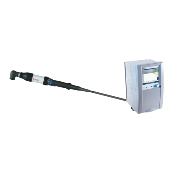
- Page 1 Rexroth Tightening System 350 Project planning aid Version AL 3 608 878 300/03.2019 <Replace this image space with your product image>...
- Page 2 © This document, as well as the data, specifications, and other information set forth in it, are the exclusive property of Bosch Rexroth AG. It may not be reproduced or given to third parties without its consent. The title page shows an exemplary configuration. The supplied product may therefore vary from the illustration.
- Page 3 Type of Documentation Project planning Document Typecode DOK-SYS350-DOKU_V2.**-PR01-EN-02F Internal File Reference 3 608 878 300_AL Purpose of Documentation This documentation describes the Rexroth Tightening System 350. Record of Revision Version Status Comments 3 608 878 300_AA/EN 04.2009 Version for Rexroth Tightening System 350 and Operating System BS350 V2.100...
- Page 4 4/641 Bosch Rexroth AG | Schraubtechnik System 350 | 3 608 878 300/2019-03...
-
Page 5: Table Of Contents
2.6.8 Protection against pressurized lines ... . .32 Rexroth Tightening System 350....103 4.3.5 Identification of the compact system/card rack field and the modules . - Page 6 6/641 Bosch Rexroth AG | Schraubtechnik Control signals and without results reset ..... 179 5.6.3 Cancelation of a tightening process by removing the start signal .
- Page 7 Schraubtechnik | Bosch Rexroth AG 7/641 6.2.7 Mass storage diagnosis ..... 252 6.9.2 Configuration of the OK/NOK counter for 6.2.8 Error messages in connection with Ethernet/FTP 258 VW-XML .
- Page 8 8/641 Bosch Rexroth AG | Schraubtechnik 7.3.5 Logging in to the tightening system (password entry) ......541 Sending and saving .
-
Page 9: About This Documentation
About this documentation This chapter contains general information on the present documentation. • Overview of this documentation (page 10) • Validity of the documentation (page 10) • Additional documentation (page 11) • Representation of information (page 13) -
Page 10: Overview Of This Documentation
Therefore, they are no general part of the scope of delivery of the Tightening System350. The receivers of these customer-specific data protocols are not provided by Bosch Rexroth. All information in this document refer to Rexroth tightening spindles and the ErgoSpin hand-held nutrunner. -
Page 11: Additional Documentation
3 608 878 300 Tightening Technology | Bosch Rexroth AG 11/641 Additional documentation Please also observe the current instructions for all tightening system components, as well as the documentation of the machine or system manufacturer and the product catalog of Rexroth Tightening System 350 available in the media directory. -
Page 12: Symbols And Representations
12/641 Bosch Rexroth AG | Tightening Technology 3 608 878 300 The safety instructions describe the following types of risk. The type of risk describes the risk if the corresponding safety instruction is not observed. The signal words have the following meanings: DANGER Death or serious bodily harm will result. -
Page 13: Designations
3 608 878 300 Tightening Technology | Bosch Rexroth AG 13/641 1.4.3 Designations Application block A maximum of 48 applications/tightening applications can be programmed in one communication unit (KE). Up to 8 tightening applications may be controlled simultaneously via the eight available application blocks (FO1 ... - Page 14 14/641 Bosch Rexroth AG | Tightening Technology 3 608 878 300 Tightening cell A tightening cell is designated as the installed hardware for at least one tightening channel and at least one data interface for communication with the operating program or the partner controller. This includes the corresponding tightening programs and tightening applications.
- Page 15 3 608 878 300 Tightening Technology | Bosch Rexroth AG 15/641 System stick A USB stick included in the scope of delivery that, amongst others, contains the installation program for the operating system BS350, as well as the firmware and documentation.
-
Page 16: Abbreviations
16/641 Bosch Rexroth AG | Tightening Technology 3 608 878 300 1.4.4 Abbreviations The following abbreviations are used in this documentation: Table 1–3: Abbreviations for the components in the tightening system Abbreviation Explanation BT356 Subrack system 350 for max. 6 tightening channels... -
Page 17: Safety Instructions
Safety instructions This chapter describes the general safety requirements for working with the Rexroth tightening system. It contains important information that is necessary for the safe use of the Rexroth tightening system. • About this chapter (page 18) • Intended use (page 21) •... -
Page 18: About This Chapter
Rexroth tightening system. If you do not have a copy of the user information for the Rexroth tightening system and components, please contact your Bosch Rexroth sales representative. Request that documents be immediately sent to the person responsible for safe operation of the Rexroth tightening system. -
Page 19: Instructions For Use
Rexroth tightening system and components. These safety instructions must be observed at all times. • Bosch Rexroth AG does not assume any liability for damages resulting from non-compliance with the safety warnings in this documentation and in the documentation of all the Rexroth tightening system components. -
Page 20: Operating Instructions
20/641 Bosch Rexroth AG | Tightening Technology 3 608 878 300 • For instructions on EMC installations, refer to the documentation for the respective component. The manufacturer of the system or machine is responsible for maintaining the limit values required by national regulations. -
Page 21: Maintenance And Repair Instructions
The products may only be used as intended. If they are not used as intended, this may result in situations that cause injuries and damage to equipment. As the manufacturer, Bosch Rexroth does not grant any warranty, assume any liability, or provide compensation for damages caused by improper use of the products. The user is solely responsible for risks caused by improper use of the products. -
Page 22: Application Areas
• If used in applications that have not been explicitly approved by Bosch Rexroth. Always observe the safety instructions in the respective documentation. System 350 | 3 608 878 300/2019-03... -
Page 23: Personnel Qualifications
3 608 878 300 Tightening Technology | Bosch Rexroth AG 23/641 Personnel qualifications Rexroth tightening systems may only be used by trained and qualified personnel. That means: • Only appropriately trained and qualified personnel are permitted to work with or near the Rexroth tightening system. -
Page 24: General Safety Instructions
24/641 Bosch Rexroth AG | Tightening Technology 3 608 878 300 General safety instructions This chapter describes general safety instructions for accident prevention. These safety instructions warn of general dangers that may e.g. result from the use or disposal of the product (or components thereof). -
Page 25: Product- And Technology-Dependent Safety Instructions For Rexroth Tightening System 350
3 608 878 300 Tightening Technology | Bosch Rexroth AG 25/641 Product- and technology-dependent safety instructions for Rexroth tightening system 350 2.6.1 Protection against accidental contact with electrical parts This section only applies to devices and components with voltages above 50 V. - Page 26 26/641 Bosch Rexroth AG | Tightening Technology 3 608 878 300 For electrical drive and filter components: DANGER Risk of injury! Risk of injury due to electric shock! Before switching on, connect the electrical equipment and the housings of all electric devices and motors to the protective conductor at the grounding points, or ground them.
-
Page 27: Protective Extra-Low Voltage For Protection Against Electric Shock
3 608 878 300 Tightening Technology | Bosch Rexroth AG 27/641 Fig. 2–3: Safety warning sticker on card rack (BT) and system box (SB) WARNING Dangerous voltage inside device! Danger to life, risk of injury due to electric shock! ... - Page 28 28/641 Bosch Rexroth AG | Tightening Technology 3 608 878 300 The monitoring devices in the drive components almost completely eliminate malfunctions in the connected drives. However, in view of personal safety, especially that involving risk of injury and/or damage to equipment, this alone is not sufficient. Until the installed monitoring devices become fully effective, faulty drive movements, whose magnitude depends on the controller type and the operating condition, must be anticipated.
- Page 29 3 608 878 300 Tightening Technology | Bosch Rexroth AG 29/641 DANGER Dangerous movements! Danger to life, risk of serious injury or damage to equipment! Ensure personal safety, either by means of monitoring devices or by superior measures directly on the system.
-
Page 30: Protection Against Magnetic And Electromagnetic Fields During Operation And Assembly
30/641 Bosch Rexroth AG | Tightening Technology 3 608 878 300 2.6.4 Protection against magnetic and electromagnetic fields during operation and assembly Magnetic and electromagnetic fields that surround live conductors and the permanent magnets of motors can pose a serious risk to persons with pacemakers, metal implants, or hearing aids. -
Page 31: Protection During Handling And Assembly
3 608 878 300 Tightening Technology | Bosch Rexroth AG 31/641 2.6.6 Protection during handling and assembly Under unfavorable conditions, handling or assembling specific parts in an unsuitable manner could cause injuries. CAUTION Risk of injury due to improper handling! Injury due to crushing, shearing, cutting, impact! ... -
Page 32: Protection Against Pressurized Lines
32/641 Bosch Rexroth AG | Tightening Technology 3 608 878 300 2.6.8 Protection against pressurized lines According to the specifications in the planning documents, liquid-cooled and forced-air-cooled motors and drive controllers, as well as forced-air-driven leads, may be supplied with external, pressurized media such as compressed air, hydraulic fluid, coolant, and coolant lubricant. - Page 33 Introduction to the Tightening System 350 This chapter gives an overview of the Rexroth Tightening System 350. It describes the individual components and explains how they are integrated in the entire system. • The Tightening System 350 (page 34) •...
-
Page 34: The Tightening System 350
Rexroth Tightening System 350. The Nexo cordless Wi-Fi nutrunner can be connected to a CS351 compact system with IL (integrated logic) as of version V2.300 of the Rexroth Tightening System 350. See "Nexo" documentation. System 350 | 3 608 878 300/2019-03... - Page 35 3 608 878 300 Tightening Technology | Bosch Rexroth AG 35/641 The CS351 compact system consists of a housing that contains the entire control and power electronics for one tightening channel. The CS351 compact system is suitable for the connection of a tightening spindle or an ErgoSpin hand-held nutrunner.
- Page 36 Rexroth Open Protocol, see „Rexroth Open Protocol“ from page 330. Programming Programming is implemented via a laptop or PC. 1) This function is available from version V2.300 of the Rexroth Tightening System 350. System 350 | 3 608 878 300/2019-03...
-
Page 37: Modular System
3 608 878 300 Tightening Technology | Bosch Rexroth AG 37/641 Variants There are the following compact system variants for connecting an ErgoSpin or CC-ErgoSpin hand-held nutrunner: • CS351E-G with TFT display (resolution 640x480) with touch screen • CS351E-G IL, additionally with integrated logic (see "Project planning" documentation of the Rexroth Tightening System 350) •... - Page 38 Tightening spindle with connection cable or ErgoSpin hand-held nutrunner with connection cable Version V2.200 or higher of the Rexroth Tightening System 350 features the additional option of networking a compact system serving as slave with the modular system, see Fig. 3–3. In such a configuration the compact system replaces the control unit.
-
Page 39: Description Of The Tightening System 350
3 608 878 300 Tightening Technology | Bosch Rexroth AG 39/641 Description of the Tightening System 350 The components of the tightening system are briefly described below. The Nexo cordless Wi-Fi nutrunner can be connected from V2.300 of the Rexroth Tightening System 350. - Page 40 40/641 Bosch Rexroth AG | Tightening Technology 3 608 878 300 The following connections are on the outside of the device: X3U3 X3U3 XDS1 XDS2 CS351E CS351S Fig. 3–6: Connections on the outside of the compact system CS351 X3U3 USB device interface, compatible with specification 2.0, with bolted-down cover...
- Page 41 3 608 878 300 Tightening Technology | Bosch Rexroth AG 41/641 Reboot X6MSD2 X3U6 X3U7 X3U8 X3C2 XDVI2 X7E4 X7E5 Fig. 3–8: Interfaces of the integrated computer unit at the CS351 compact system Depending on the compact system, the following interfaces are available:...
- Page 42 42/641 Bosch Rexroth AG | Tightening Technology 3 608 878 300 The following table indicates the available interfaces at the various compact systems: Table 3–1: Interfaces on the CS351 compact system Interface CS351S-D/IL CS351S-G/IL CS351S-G+ CS351S-D NK CC-CS351E-D CS351E-D/IL CS351E-G/IL...
-
Page 43: Modular System
3 608 878 300 Tightening Technology | Bosch Rexroth AG 43/641 3.4.2 Modular system 3.4.2.1 SB356 system box Fig. 3–9: SB356 system box The IP54-protected SB356 system box is designed for operation without a control cabinet. The system box includes the control and power electronics for up to six tightening channels. In the simplest case, this is a VM power supply module for internal system power supply, an SE control unit, an LT, LTU or LTS/ LTE servo amplifier, as well as a KE communication unit for internal and external communication. - Page 44 44/641 Bosch Rexroth AG | Tightening Technology 3 608 878 300 3.4.2.3 VM350 power supply module The VM350 power supply module is used to supply power to all slots in the card rack field or in the system box. One VM350 is required for each card rack field or system box. The VM350 has an interface at the front.
- Page 45 3 608 878 300 Tightening Technology | Bosch Rexroth AG 45/641 3.4.2.6 KE350 and KE350G IL communication units The KE350 and KE350G IL communication units coordinate the individual control units and organize the interfaces with external systems (e. g. PLC or central computer). The internal system communication with the control units is implemented via a standard bus system.
-
Page 46: Tightening Spindles
46/641 Bosch Rexroth AG | Tightening Technology 3 608 878 300 3.4.3 Tightening spindles The modular design of Rexroth's tightening spindles (Fig. 3–11) allows for very exact adjustment to the tightening job and the precision requirements. You can obtain the highest possible level of system reliability by installing a redundant measurement transducer in the tightening spindle. -
Page 47: Ergospin Hand-Held Nutrunner
3 608 878 300 Tightening Technology | Bosch Rexroth AG 47/641 3.4.3.1 BG5+ with increased performance By using the power reserves of the servo amplifier LTS350 and LT355 and the EC motor EC305, the spindle limits of a stationary spindle of size 5 can be expanded as follows:... - Page 48 48/641 Bosch Rexroth AG | Tightening Technology 3 608 878 300 Torque converter (b) The torque system monitors the torque during a tightening process. The measurement is made via DMS technology: In the nutrunner, the generated signal is converted, digitalized, and transferred contact-free to the tightening controller as a protocol checked for plausibility.
- Page 49 3 608 878 300 Tightening Technology | Bosch Rexroth AG 49/641 Laser radiation – Laser class 2! Light emission in the visible range! LASER LIGHT Laserstrahlung DO NOT STARE INTO THE BEAM CLASS 2 LASER PRODUCT Nicht in den Strahl blicken...
- Page 50 50/641 Bosch Rexroth AG | Tightening Technology 3 608 878 300 Table 3–6: Supported barcode types (barcode scanner in the ErgoSpin) Barcode type Length Option UPC-E0 with 2 Supplements – Check Digit Redundancy Preamble Security Level 0…3 UPC-E0 with 5 Supplements –...
- Page 51 3 608 878 300 Tightening Technology | Bosch Rexroth AG 51/641 Table 3–6: Supported barcode types (barcode scanner in the ErgoSpin) Barcode type Length Option Trioptic Code39 Redundancy Security Level 0…3 Digit verification Check Digit Convert Code39 to Code 32 Redundancy Security Level 0…3...
- Page 52 52/641 Bosch Rexroth AG | Tightening Technology 3 608 878 300 code-specific length one discrete length two discrete lengths The length may be between L1 and L2; if, e.g., L1 = 4, L2 = 9, then L1-L2 = 4…9 any lengths The laser beam of the barcode scanner can be activated using the ErgoSpin tool button.
- Page 53 3 608 878 300 Tightening Technology | Bosch Rexroth AG 53/641 Fig. 3–15: Example: ESV025 hand-held nutrunner Starting the hand-held nutrunner To start the hand-held nutrunner, both start switches have to be pressed simultaneously within 0.5 seconds. Before restarting the hand-held nutrunner, both start switches have to be released. If fully assembled, it complies with all requirements for 2-hand operation according to type III A (EN 574, ISO 13851).
-
Page 54: Cables
54/641 Bosch Rexroth AG | Tightening Technology 3 608 878 300 3.4.4.1 CC-ErgoSpin CC-ErgoSpin hand-held nutrunners are available as of version V2.300 SP1 of the Rexroth Tightening System 350. The CC-ErgoSpin series includes hand-held electric/tightening tools of various sizes that may be used with the compact systems CS351 and CC-CS351. -
Page 55: Integration In An Entire System
3 608 878 300 Tightening Technology | Bosch Rexroth AG 55/641 3.4.6.2 IndraWorks The uniform engineering framework IndraWorks is consistently available for all systems from Rexroth. It allows for fast and transparent access to all functions and system data of the automation components. -
Page 56: Modular System
56/641 Bosch Rexroth AG | Tightening Technology 3 608 878 300 3.5.2 Modular system The system can be externally connected to an entire system via various control and results output interfaces. The internal communication takes place via bus systems (see Fig. 3–17). This enables integration of the electronic components in card rack fields or system boxes, as well as the single-cable solution between the servo amplifier and the tightening spindle or ErgoSpin. -
Page 57: Communication Between The Tightening System And The Bs350 Operating System
3 608 878 300 Tightening Technology | Bosch Rexroth AG 57/641 Results WLAN Access PC / Laptop Point TCP/IP Field bus Serial coupling - RS232 - RS422 - 20 mA Internal bus Tightening cell Printer / scanner Fig. 3–17: Modular system communication options 3.5.3... -
Page 58: External Communication
Process Quality Manager (PQM) Process Quality Manager (PQM) is a software solution of Bosch Rexroth. It is designed to recognize and avoid non-conformities and errors in the production process as soon as possible. PQM offers safe and reliable monitoring and documentation of production processes. -
Page 59: Construction Guidelines
Construction guidelines This chapter describes the structure of a tightening cell made of the components of the Rexroth Tightening System 350. For further information, refer to: www.boschrexroth.com/tightening • Design of a bolted connection (page 60) • Tightening system design (page 65) •... -
Page 60: Design Of A Bolted Connection
60/641 Bosch Rexroth AG | Tightening Technology 3 608 878 300 Design of a bolted connection The planning of a tightening system starts with the definition of the tightenings that are to be implemented. This determines the selection of the appropriate tightening spindle or hand-held nutrunner. -
Page 61: Determination Of The Required Torque To Create A Bolted Connection
3 608 878 300 Tightening Technology | Bosch Rexroth AG 61/641 4.1.2 Determination of the required torque to create a bolted connection When creating bolted connections, the mounting clamp force (clamping force) required for a secure connection of the parts is usually specified. As the clamping force is difficult to measure, the tightening torque or angle of turn is used as a parameter for the clamping force. - Page 62 62/641 Bosch Rexroth AG | Tightening Technology 3 608 878 300 Distortion Force Compression of the connected parts Extension of the bolt Amount of settling Mounting clamp force before settling process Mounting clamp force after settling process Loss of mounting clamp force due to settling process Settling can be avoided or decreased using the following procedures: •...
- Page 63 3 608 878 300 Tightening Technology | Bosch Rexroth AG 63/641 4.1.2.6 Clamping force table according to VDI 2230 The following table lists the guide values for mounting clamp forces (F ) and tightening torques (T ) in relation to a friction factor (...
-
Page 64: Torque Ranges
64/641 Bosch Rexroth AG | Tightening Technology 3 608 878 300 4.1.3 Torque ranges Four different spindle sizes (=motor sizes) are available in the tightening system. A torque range of 0.6- 1000 Nm is provided by various combinations of spindle components: Table 4–2: Torque ranges of tightening spindles in various sizes... -
Page 65: Tightening Processes
3 608 878 300 Tightening Technology | Bosch Rexroth AG 65/641 4.1.5 Tightening processes A bolted connection should be designed in a way that the minimum mounting clamp force reached guarantees the function of the bolted connection, but the maximum mounting clamp force does not destroy the bolted connection or the bolt. - Page 66 If a redundant measurement transducer is not used, the 3VMC is installed directly at the planetary gearbox; the 4VMC requires a 4AVG adapter. As of version 2.600 of the Rexroth Tightening System 350, the offset output drives which are docking- enabled are supported with integrated VMC...-SD/-SP (external square) / VMC...-QC (quick-change chuck) measurement transducer.
- Page 67 3 608 878 300 Tightening Technology | Bosch Rexroth AG 67/641 Table 4–3: Angle head Code 2W011 3W027 3W050 3W090 4W130 4W220 Order number 0 608 810 0 608 810 0 608 810 0 608 810 0 608 810 0 608 810 Max.
- Page 68 68/641 Bosch Rexroth AG | Tightening Technology 3 608 878 300 Table 4–5: Minimum spindle distances for size 2 to 5 spindles with various output drives Number of tightening spindles and corresponding smallest circle diameter-Ø [mm] Size Type Offset output drive with integrated measurement 3VMC...
-
Page 69: Ergospin Hand-Held Nutrunner
3 608 878 300 Tightening Technology | Bosch Rexroth AG 69/641 Accessories Rexroth supports you with a wide range of accessories and customized solutions for all tightening tasks: • Angle heads for size 5 • Angle heads with counter bracket •... -
Page 70: Connection Cables
70/641 Bosch Rexroth AG | Tightening Technology 3 608 878 300 4.2.2.2 GripLine The GripLine hand-held nutrunner is technically identical to the SlimLine model. However, the GripLine angle head is equipped with an ergonomic plastic coating additionally. This way, the handling is improved and scratches to the workpiece are avoided. - Page 71 3 608 878 300 Tightening Technology | Bosch Rexroth AG 71/641 NOTICE Malfunction, damage to system Functional safety and system safety jeopardized Only use accessories, add-on units, and cables that have been approved for use in Rexroth tightening systems.
- Page 72 72/641 Bosch Rexroth AG | Tightening Technology 3 608 878 300 Please observe the following points when selecting cables: • Only one connection cable is required to connect the tightening spindle to the compact system or the servo amplifier. •...
- Page 73 3 608 878 300 Tightening Technology | Bosch Rexroth AG 73/641 4.2.3.2 ErgoSpin hand-held nutrunner The ErgoSpin hand-held nutrunner is connected to the LTU350/1 and/or LTE350D servo amplifier or the CS351 compact system via a connection cable. Fig. 4–6: Connection cables for ErgoSpin hand-held nutrunner ErgoSpin connection cable straight –...
-
Page 74: Control And Power Electronics
74/641 Bosch Rexroth AG | Tightening Technology 3 608 878 300 Please observe the following points when selecting cables: • Only one connection cable is required to connect the ErgoSpin hand-held nutrunner to the compact system or the servo amplifier. - Page 75 3 608 878 300 Tightening Technology | Bosch Rexroth AG 75/641 4.2.4.2 Modular system System boxes/card rack fields Tightening system components must be installed in a system box or card rack field for operation. This creates the connection between the units and provides the units with electric power.
- Page 76 76/641 Bosch Rexroth AG | Tightening Technology 3 608 878 300 Communication unit The communication unit is available in the following versions: KE350 and KE350G IL. The communication unit coordinates individual control units and organizes the interfaces to external systems (e. g. PLC or central computer).
- Page 77 Networking compact As of version V2.200 of the Rexroth Tightening System 350, there is the option to link compact systems systems as slave of types CS351E-D NK or CS351S-D NK with a card rack field or a system box with network coupler cables NKL.
-
Page 78: Connected Load
78/641 Bosch Rexroth AG | Tightening Technology 3 608 878 300 4.2.4.3 Permissible equipment for BT356/SB356 A tightening channel consists of the following components: • Tightening spindle ErgoSpin hand-held nutrunner connection cable • Control unit • Servo amplifier If the appropriate control and servo components are installed, both tightening spindles and ErgoSpin hand-held nutrunners can be connected to and operated on the SB356 system box and the BT356 card rack field. - Page 79 3 608 878 300 Tightening Technology | Bosch Rexroth AG 79/641 Mains voltages The BT356 card rack field has been designed for 230 V nominal voltage. The SB356 system box has been designed for a nominal voltage of 380 V to 500 V (400 V at factory): Table 4–10:...
- Page 80 80/641 Bosch Rexroth AG | Tightening Technology 3 608 878 300 Mains connection for card rack fields Card rack fields have been designed for 3 230 V alternating voltage. The card rack fields are intended for operation in industrial environments (emission class A), i. e.: •...
- Page 81 3 608 878 300 Tightening Technology | Bosch Rexroth AG 81/641 Combined connection of several card rack fields to the mains supply Connecting two BT356 to the Mains supply BT356 BT356 Fig. 4–9: Connection example for 2 BT356 card rack fields with a shared isolating transformer...
-
Page 82: Calculation Of Power Loss
Per IM Power loss in ready mode 23 W with activated screensaver Available as of version V2.200 of the Rexroth Tightening System 350 Calculation of power loss when idle: = Total of power losses of all installed components when idle. - Page 83 3 608 878 300 Tightening Technology | Bosch Rexroth AG 83/641 Base load Tightening Pre-tightening Final tightening Fig. 4–11: Power diagram for a 3-step tightening process If a torque/power curve such as in Fig. 4–11 is assumed, the average power is calculated as follows:...
-
Page 84: Reduce Cycle Time
84/641 Bosch Rexroth AG | Tightening Technology 3 608 878 300 Calculation of total power loss --------------------------------------------------------------------------------------------------------------------- 4.2.7 Reduce cycle time The possible cycle time of a tightening spindle (effective minimum time for a tightening process) is determined by two factors: •... - Page 85 3 608 878 300 Tightening Technology | Bosch Rexroth AG 85/641 T [ Nm] T [ Nm] 3GE67 3GE67 3GE27 3GE27 EC303/3GE67 10 12 n [1/min] t [s] Fig. 4–13: Maximum performance of a tightening channel (left) and maximum possible tightening torque depending on cycle time and tightening case hardness (right) for size 3 spindles with i >...
- Page 86 86/641 Bosch Rexroth AG | Tightening Technology 3 608 878 300 T [ Nm] 5GE68 5GE68 T [ Nm] 5GE19 5GE19 EC305/5GE68 12 16 20 24 n [1/min] t [s] Fig. 4–15: Maximum performance of a tightening channel (left) and maximum possible tightening torque depending on cycle time and tightening case hardness (right) for size 5 spindles with i >...
- Page 87 3 608 878 300 Tightening Technology | Bosch Rexroth AG 87/641 Example • Size 5 tightening spindle with 5GE68 planetary gearbox and the following output drives: – GK3C…/GL3C… or VNK3C…/VNL3C… with transmission ratio 1 – Tightening torque 400Nm –1 A maximum output drive speed of 145min is possible with a GK3C…/GL3C…...
-
Page 88: Electrical Connections Between The Tightening System And The Production Environment
88/641 Bosch Rexroth AG | Tightening Technology 3 608 878 300 4.2.8 Electrical connections between the tightening system and the production environment The tightening system, as well as the communication unit or control unit, have a variety of electrical interfaces for programming, controlling, and results data communication. -
Page 89: Integration Of The Tightening System In An Installation
• Acknowledgement of errors in error class 3 • As of version V2.500 of the Rexroth Tightening System 350: Parameterization of the correction factor for adjustment of the tightening system to a reference measuring system The LC display shows: •... - Page 90 90/641 Bosch Rexroth AG | Tightening Technology 3 608 878 300 4.3.1.1 Constructive measures for maintaining the ambient conditions NOTICE Penetration of water and high humidity If water or condensation penetrate, this may damage the control and power electronics. ...
- Page 91 3 608 878 300 Tightening Technology | Bosch Rexroth AG 91/641 Temperature specifications The following temperature limit values apply when using the system components: Table 4–19: Permissible ambient temperatures °C System component Temperature range [ – Compact system – System box –...
- Page 92 92/641 Bosch Rexroth AG | Tightening Technology 3 608 878 300 The system should basically be considered intrinsically safe: If the system detects an overtemperature fault, it will report a system error and remain blocked until it is in the permissible temperature range again.
- Page 93 3 608 878 300 Tightening Technology | Bosch Rexroth AG 93/641 Remedy: • If this type of system is used, potential equalization must be ensured on site. This means, an additional slide with current collector may need to be installed for grounding of the busbar system at the system on site.
- Page 94 94/641 Bosch Rexroth AG | Tightening Technology 3 608 878 300 Motor-breaker circuit with ErgoSpin or tightening spindle Cut-out via the internal motor contactors After a cut-out via the motor contactor, the motor phases are electromechanically isolated from the power supply.
- Page 95 3 608 878 300 Tightening Technology | Bosch Rexroth AG 95/641 Use of the ErgoSpin hand-held nutrunner as a tightening spindle If the ErgoSpin hand-held nutrunner is used as a tightening spindle, the start switch must be continually actuated. This is applicable to both the...
- Page 96 96/641 Bosch Rexroth AG | Tightening Technology 3 608 878 300 Example emergency-OFF with SB356 and BT356 emergency OFF switch direct XDN2 VEE NH 1 mm EXIT Reset Reset Reset X1S1 XDN2 X1S2 VM350 LTU350/1 LTU350/1 Fig. 4–24: Shutdown via VM350 Example of the integration into a user-side emergency stop concept An additional external 24V power pack can be connected via the X1S2 interface.
- Page 97 3 608 878 300 Tightening Technology | Bosch Rexroth AG 97/641 XDN2 Power pack in accordance with EN50178* 24 V X1S2 EXIT Reset Reset Reset X1S1 XDN2 X1S2 Emergency-OFF CONTROLLER VM350 LTU350/1 LTU350/1 24 V 24 V Terminals -XL x and -XL y...
-
Page 98: Design Of Mains Connection
98/641 Bosch Rexroth AG | Tightening Technology 3 608 878 300 Example for hand-held tightening spindles with switch S1 The tightening spindles are stopped by the servo amplifiers and the internal automatic cutouts for the individual servo amplifiers are opened when the S1 switch is activated. This tightening job abort leads to an error message in the controller. -
Page 99: Grounding
3 608 878 300 Tightening Technology | Bosch Rexroth AG 99/641 4.3.2.1 Cable protection switch compact system The compact system has built-in fuses. Pre-fuses are therefore only required for cable protection. The minimum protection values are listed in Table 4–21. - Page 100 100/641 Bosch Rexroth AG | Tightening Technology 3 608 878 300 This feature facilitates setting up the system with a ground cable for the user. A maximum of 5 linked system boxes is recommended. A higher number of system boxes would not comply with other valid guidelines.
- Page 101 3 608 878 300 Tightening Technology | Bosch Rexroth AG 101/641 Please note here that not only large distances may cause these potential differences, but also other consumers. In particular, power electronics equipment is suitable for inputting fast, pulsed currents in the ground wire with switching processes.
- Page 102 102/641 Bosch Rexroth AG | Tightening Technology 3 608 878 300 (1) 10 mm gn-ge (2) Connection cable for ErgoSpin/tightening spindle (3) ErgoSpin/tightening spindle (4) I (5) Workpiece (6) Additional potential equalization (7) U Disrupting currents can be discharged with this additional potential equalization. There is then no potential difference between the workpiece and tightening spindle.
-
Page 103: Performance Level (Pl) Within The Rexroth Tightening System 350
Tightening Technology | Bosch Rexroth AG 103/641 4.3.4 Performance level (PL) within the Rexroth Tightening System 350 The basis of this section is that every machine manufacturer is obliged to identify possible dangers this machine might pose for the operator and to remove the risk related to the danger. In situations in which the danger cannot be removed, every machine manufacturer is obliged to reduce this danger to the largest possible extent. - Page 104 Calculation basis PL and PFHd or MTTFd For the Rexroth Tightening System 350, the PFHd or MTTFd value is specified in addition to the performance level (PL). As within the safety function of the tightening system, one uses also...
- Page 105 3 608 878 300 Tightening Technology | Bosch Rexroth AG 105/641 Performance level (PL) and PFHd within the Rexroth Tightening System 350 Table 4–22: Performance level (PL) and PFHd within the Rexroth Tightening System 350 Controller MTTFd Performance Comments Category...
-
Page 106: Identification Of The Compact System/Card Rack Field And The Modules
106/641 Bosch Rexroth AG | Tightening Technology 3 608 878 300 1According to ISO 13849-1:2006 2) ATTENTION: To ensure that the ErgoSpin hand-held nutrunner is integrated in the emergency OFF circuit (emergency OFF interface XDN2), switch S2 must be in position "1", see chapter 4, Tab. 9 of the LTS350D/LTE350D operating instructions. In this configuration, the start switch of the ErgoSpin hand-held nutrunner no longer has an effect on the motor contactor. - Page 107 3 608 878 300 Tightening Technology | Bosch Rexroth AG 107/641 Control cabinets from Rexroth’s delivery program The control cabinets allow the Tightening System 350 to be easily integrated into tightening installations. These control cabinets are optimized for the needs of the tightening system. All control cabinets are available in two standard dimensions: 1800 ...
-
Page 108: Rework Station
108/641 Bosch Rexroth AG | Tightening Technology 3 608 878 300 Fig. 4–32: Separable cable ducts in control cabinet Control cabinets from other manufacturers must be equipped with corresponding cable ducts, to ensure compliance with IP 54 protection class. 4.3.7 Rework station Rework stations are always needed where automatic tightenings have generated a faulty tightening (e. -
Page 109: Use Of Additional Components (Accessories)
3 608 878 300 Tightening Technology | Bosch Rexroth AG 109/641 Work sequence for the rework station Select tightening program appropriate for workpiece Position nutrunner Start After the end of the tightening (OK/NOK display), remove the nutrunner 4.3.8 Use of additional components (accessories) Rexroth supports you with a wide range of accessories and customized solutions for all tightening tasks. - Page 110 110/641 Bosch Rexroth AG | Tightening Technology 3 608 878 300 4.3.8.1 Socket tray The socket tray helps to select the appropriate tightening program depending on the tool used (socket). For control, there are two types of socket tray: •...
- Page 111 3 608 878 300 Tightening Technology | Bosch Rexroth AG 111/641 4.3.8.2 Program selector The program selector is used to select the appropriate tightening program or tightening application for hand-held nutrunners: Fig. 4–34: Exemplary figure of program selector The program selector is available in three versions: •...
-
Page 112: Compatibility With Foreign Substances
Planning assistance 4.6.1 3-D/CAD data All CAD data from Bosch Rexroth are available free of charge at the following internet address. www.boschrexroth.com/tightening Use the links on the website displayed to navigate to the appropriate component. The CAD data are available on the CAD tab. -
Page 113: Circuit Diagrams
3 608 878 300 Tightening Technology | Bosch Rexroth AG 113/641 4.6.2 Circuit diagrams Fig. 4–36: Circuit diagram example for connecting a transformer to a BT356 card rack field System 350 | 3 608 878 300/2019-03... - Page 114 114/641 Bosch Rexroth AG | Tightening Technology 3 608 878 300 Fig. 4–37: Circuit diagram example for connecting several BT356 card rack fields System 350 | 3 608 878 300/2019-03...
- Page 115 3 608 878 300 Tightening Technology | Bosch Rexroth AG 115/641 Fig. 4–38: Circuit diagram example for networking several BT356 card rack fields with NK350(S) network couplers and motor breaker System 350 | 3 608 878 300/2019-03...
- Page 116 116/641 Bosch Rexroth AG | Tightening Technology 3 608 878 300 Fig. 4–39: Circuit diagram example for connecting tightening spindles to a BT356 card rack field System 350 | 3 608 878 300/2019-03...
- Page 117 3 608 878 300 Tightening Technology | Bosch Rexroth AG 117/641 Fig. 4–40: Circuit diagram example for connecting a KE in a BT356 card rack field System 350 | 3 608 878 300/2019-03...
- Page 118 118/641 Bosch Rexroth AG | Tightening Technology 3 608 878 300 Fig. 4–41: Circuit diagram example for the start delay at a BT356 card rack field System 350 | 3 608 878 300/2019-03...
- Page 119 3 608 878 300 Tightening Technology | Bosch Rexroth AG 119/641 Fig. 4–42: Circuit diagram example for PNOZ System 350 | 3 608 878 300/2019-03...
- Page 120 120/641 Bosch Rexroth AG | Tightening Technology 3 608 878 300 System 350 | 3 608 878 300/2019-03...
-
Page 121: Control Signals
Control signals This chapter contains detailed information on the control signals in the Rexroth Tightening System 350. The information provided in this document refers to software versions V2.100 and higher of the BS350 operating system. • Definitions (page 122) • Description of all PLC signals (page 126) •... -
Page 122: Definitions
122/641 Bosch Rexroth AG | Tightening Technology 3 608 878 300 Definitions The information provided in this chapter refers to Rexroth tightening spindles and the ErgoSpin hand-held nutrunner. For information on the Nexo cordless Wi-Fi nutrunner, please refer to the "Nexo"... -
Page 123: Application Block (Fo)
The configuration to be used can either be obtained offline from a configuration file (*.scg with SE/CS or *.kcg with KE) or online from the tightening controller. As of version V2.700 of the Rexroth Tightening System 350, the entries in the PLC assignment table can be sorted in alphabetically ascending/descending order. - Page 124 5.1.5.1 PLC signal name editing As of version V2.600 of the Rexroth Tightening System 350, the names of PLC signals can be edited. PLC signals can be edited in online mode (BS350 connected to a tightening system) or offline mode (BS350 is not connected to a tightening system).
- Page 125 5.1.5.2 Determining settings for PLC signal names As of version V2.700 of the Rexroth Tightening System 350, the display and color setting of the changed PLC signal name can be selected. In the operating system, select Extras Options.
-
Page 126: Description Of All Plc Signals
126/641 Bosch Rexroth AG | Tightening Technology 3 608 878 300 Description of all PLC signals The sections below provide a description of all PLC signals in alphabetic order. 5.2.1 Input signals ActEn Active Enable: Enables a single tightening process Input signal used for: •... - Page 127 The inputs are transferred from the KE to the SE, irrespective of enabling (Ch x.y SEn). AutoBackup Auto backup: Automatic data backup This signal is available from version V2.600 of the Rexroth Tightening System 350. Input signal used for: •...
- Page 128 128/641 Bosch Rexroth AG | Tightening Technology 3 608 878 300 AutoBackupF Auto backup fault: Automatic data backup This signal is available from version V2.600 of the Rexroth Tightening System 350. Input signal used for: • Compact system (AutoBackupF) •...
- Page 129 3 608 878 300 Tightening Technology | Bosch Rexroth AG 129/641 AutoRestoreRun Auto restore run: Sequence of the automatic restore process This signal is available from version V2.600 of the Rexroth Tightening System 350. Input signal used for: • Compact system (AutoRestoreRun) •...
- Page 130 No zero point test is implemented when program no. 99 is started with the signal Ccw. CcwAND Counter clock wise AND: AND operation for loosening program This signal is available as of version V2.300 of the Rexroth Tightening System 350. Input signal used for: •...
- Page 131 Speed monitoring is not performed when program no. 47 is started via the sequence test! CwAND Clock wise AND: AND operation for tightening program This signal is available as of version V2.300 of the Rexroth Tightening System 350. Input signal used for: •...
- Page 132 OK/NOK counter is reached, the channel is disabled (optional) and evaluated with CntNOK = "high". Disable Disables the application block This signal is available as of version V2.300 of the Rexroth Tightening System 350. Input signal used for: • Communication unit in application operation (FO x Disable) When the Disable signal is set to "high", the corresponding application block is disabled.
- Page 133 Tightening Technology | Bosch Rexroth AG 133/641 ES LED Green ErgoSpin LED Green: Sets the green ErgoSpin LED This signal is available as of version V2.300 of the Rexroth Tightening System 350. Input signal used for: • Tightening channel (EsLEDGreen) •...
- Page 134 Job Abort Aborts a job This signal is available in the compact system as of version V2.300, KE as of V2.400 and SE as of V2.500 of the Rexroth Tightening System 350. Input signal used for: • Tightening channel: Compact system (Job Abort) •...
- Page 135 Job Start Starts a job This signal is available in the compact system as of version V2.300, KE as of V2.400 and SE as of V2.500 of the Rexroth Tightening System 350. Input signal used for: • Tightening channel: Compact system (Job Start) •...
- Page 136 InCyCcw is otherwise not reset. NOKAcByps Not OK acknowledge bypass: NOK-acknowledgement with deselected spindles This signal is available from version V2.200 of the Rexroth Tightening System 350. Input signal used for: • Communication unit in application operation (FO x NOKAcByps) The tightening system also features the option of preventing further starts after NOK tightening (NOKByps to "high").
- Page 137 3 608 878 300 Tightening Technology | Bosch Rexroth AG 137/641 From version V2.200 of the Rexroth Tightening System 350, up to 99 tightening programs are possible (program 0 to 98). As before, program 99 is the loosening program. ResF...
- Page 138 138/641 Bosch Rexroth AG | Tightening Technology 3 608 878 300 Signal Enable: Enables signals Input signal used for: • Tightening channel (SEn) • Communication unit in single-channel operation (CH x.y SEn) By setting the Ch x.y SEn signal, the user enables the signals of a tightening controller at the control interface of the KE for single-channel operation via the KE.
- Page 139 3 608 878 300 Tightening Technology | Bosch Rexroth AG 139/641 UsrIn 1 User Input 1: External input signal 1 Input signal used for: • Tightening channel (UsrIn 1) • Communication unit in single-channel operation (CH x.y UsrIn 1) This signal can be used as an external input signal for program functions, e.g. with Target function input or Conditional input branch.
-
Page 140: Output Signals
140/641 Bosch Rexroth AG | Tightening Technology 3 608 878 300 5.2.2 Output signals Ack0-7 Acknowledge 0-7: Acknowledges the program or application selection Output signal used for: • Tightening channel (Ack0-7) • Communication unit in single-channel operation (CH x.y Ack0-7) •... - Page 141 3 608 878 300 Tightening Technology | Bosch Rexroth AG 141/641 AppOut 0-15 Application Out Bit 0-15: Application-specific output signal Output signal used for: • Tightening channel (AppOut) • Communication unit in single-channel operation (CH x.y AppOut, CH x.y SE AppOut) •...
- Page 142 This signal is only active for tightening channels with ErgoSpin. The signal is only updated outside of the tightening operation. CheckEs Check ErgoSpin: Test interval ErgoSpin reached As of version V2.600 of the Rexroth Tightening System 350, this signal is replaced by the MntTool signal. Output signal used for: • Tightening channel (CheckEs) •...
- Page 143 Data services. DisableAck Disable acknowledge: Acknowledges that an application block is disabled This signal is available as of version V2.300 of the Rexroth Tightening System 350. Output signal used for: • Communication unit in application operation (FO x DisableAck) System 350 | 3 608 878 300/2019-03...
- Page 144 (EnScanAck = 1) or it is locked or its release time has expired (EnScanAck = 0). ES LED Gr Ack ErgoSpin LED Green acknowledge: Acknowledges the green ErgoSpin LED This signal is available as of version V2.300 of the Rexroth Tightening System 350. Output signal used for: •...
- Page 145 Results description after a completed tightening sequence. The gradient is below the defined tolerance window. GO_Rdy Geared offset head ready: Flat output drive referenced This signal is available as of version V2.400 of the Rexroth Tightening System 350. Output signal used for: • Tightening channel (GO_Rdy) •...
- Page 146 InCyCm In Cycle Complete: Time period elapsing while tightening is active, including evaluation and completed results output This signal is available as of version V2.300 of the Rexroth Tightening System 350. Output signal used for: • Tightening channel (InCyCm) •...
- Page 147 Tightening Technology | Bosch Rexroth AG 147/641 InCyEv In Cycle Evaluation: Time period elapsing while tightening is active, including completed evaluation This signal is available as of version V2.300 of the Rexroth Tightening System 350. Output signal used for: • Tightening channel (InCyEv) •...
- Page 148 Job Ok Job OK: The job result is okay This signal is available in the compact system as of version V2.300, KE as of V2.400 and SE as of V2.500 of the Rexroth Tightening System 350. Output signal used for: •...
- Page 149 The signal, in connection with the modular system (SE or KE) is always "high", i.e., it is not changed by a motor stop. • As of version V2.600 of the Rexroth Tightening System 350: LTE350D and LTS350D (CHx.y MStop) The signal, in connection with the modular system (SE or KE) is switched from "high" to "low" if the motor stop is triggered.
- Page 150 150/641 Bosch Rexroth AG | Tightening Technology 3 608 878 300 In contrast to theNOK signal, theNOKByps signal only indicates that a tightening application is NOK if a NOK-tightening is present in an active tightening channel. However, bypassed tightening channels are evaluated with OK.
- Page 151 3 608 878 300 Tightening Technology | Bosch Rexroth AG 151/641 Possible causes for KE Rdy = "low" are: • KE boot process is running • KE350 / KE350G IL system error • Sequence test activated by BS350 Signal curves are described in section Behavior of FC Rdy and FO x Rdy in ByPass mode.
- Page 152 "low", the SpDckAck signal also changes to "low" provided the tightening system has been reconfigured successfully. StartBn Start button: State of the ErgoSpin start switch This signal is available as of version V2.300 of the Rexroth Tightening System 350. Output signal used for: • Tightening channel (StartBn) •...
- Page 153 3 608 878 300 Tightening Technology | Bosch Rexroth AG 153/641 CAUTION The StartBn signal is to be used with caution. The PLC has the sovereignty to start tightening programs that are rotating clockwise or counter-clockwise directly one after the other.
- Page 154 154/641 Bosch Rexroth AG | Tightening Technology 3 608 878 300 TorqCtrL Torque control too low: Tightening torque too low Output signal used for: • Tightening channel (TorqCtrL) • Communication unit in single-channel operation (CH x.y TorqCtrL) Results description after a completed tightening sequence. The tightening torque is below the defined limit.
- Page 155 3 608 878 300 Tightening Technology | Bosch Rexroth AG 155/641 TorqRgeH Torque range too high: Torque range too high Output signal used for: • Tightening channel (TorqRgeH) • Communication unit in single-channel operation (CH x.y TorqRgeH) Results description after a completed tightening sequence. The torque range is above the defined tolerance window.
-
Page 156: Ke Communication Unit
156/641 Bosch Rexroth AG | Tightening Technology 3 608 878 300 TorqRgeL Torque range too low: Torque range too low Output signal used for: • Tightening channel (TorqRgeL) • Communication unit in single-channel operation (CH x.y TorqRgeL) Results description after a completed tightening sequence. The torque range is below the defined tolerance window. - Page 157 3 608 878 300 Tightening Technology | Bosch Rexroth AG 157/641 Rexroth Tightening System 350 This function ("KE…") is a future functional extension of the . That means that Rexroth Tightening System 350 the function is not supported in the current version of the , yet.
- Page 158 158/641 Bosch Rexroth AG | Tightening Technology 3 608 878 300 Function FO x ... Description Signals FO x ... ResRs Reset Result Reset tightening application result ResRsAll Reset Result All With x = 1…8, this signal leads to FO x ResRs on the application level, as well as Ch x.y ResRs...
- Page 159 3 608 878 300 Tightening Technology | Bosch Rexroth AG 159/641 Function channel x.y ... Description Signals CH x.y CwAND Clock wise AND AND operation for tightening program. CyCmp Cycle Complete End of tightening. DisRp Disable Report Results output to subsequent tightening...
- Page 160 CH x.y (fastening channel) tightening channel As of version V2.600 of the Rexroth Tightening System 350, this signal is replaced by the MntTool signal. The KE control interface can be used to access single-channel signals. The extension Ch x.y is preset in addition to the single-channel signal, e.g.
- Page 161 3 608 878 300 Tightening Technology | Bosch Rexroth AG 161/641 For an explanation of these signals (without "CH x.y.."), see chapter Description of all PLC signals from page 126. System 350 | 3 608 878 300/2019-03...
-
Page 162: Sequence
162/641 Bosch Rexroth AG | Tightening Technology 3 608 878 300 5.3.2 Sequence The following flow chart provides an overview of the sequence of the individual control signals and the subsequent switching conditions between the beginning and end of a simple tightening process. Use of the individual PLC signals depends on the individual case of application, e.g. -
Page 163: Ke Timing Diagrams
3 608 878 300 Tightening Technology | Bosch Rexroth AG 163/641 KE timing diagrams This section shows several process examples and the relevant PLC signals in chronological sequence. As Rexroth tightening systems are used in a wide variety of control environments, it cannot be guaranteed that the PLC signals are always available at defined times, e.g. -
Page 164: Normal Sequence Of A Tightening Application (Ok Tightening)
164/641 Bosch Rexroth AG | Tightening Technology 3 608 878 300 5.4.3 Normal sequence of a tightening application (OK tightening) Input, Output There is a delay between the OK/NOK an CyCmp signals during results output, e.g. via the printer interface. OK/NOK comes at the end of the tightening and CyCmp only after the data output. This delay depends on the data output and can last from several 100 ms up to several seconds. -
Page 165: Attempted Start Of An Invalid (E.g. Not Programmed Or Incorrectly Programmed) Tightening Application
3 608 878 300 Tightening Technology | Bosch Rexroth AG 165/641 5.4.5 Attempted start of an invalid (e.g. not programmed or incorrectly programmed) tightening application (application 2) Input, Output 5.4.6 Controlling the ErgoSpin LEDs by an external controller The Cw PLC signal is applied to the ErgoSpin start switch. The external controller sets the LEDs on the ErgoSpin and controls the tightening operation. -
Page 166: Results Reset (Fo X Resrs) After The End Of A Tightening Application
166/641 Bosch Rexroth AG | Tightening Technology 3 608 878 300 5.4.7 Results reset (FO x ResRs) after the end of a tightening application Input, Output 5.4.8 Results reset (FO x ResRs) during completion of a tightening application Input, Output... -
Page 167: Cancelation Of A Tightening Application By Removing The Start Signal
3 608 878 300 Tightening Technology | Bosch Rexroth AG 167/641 5.4.9 Cancelation of a tightening application by removing the start signal Input, Output 5.4.10 Cancelation of a tightening application by KE system error Input, Output System 350 | 3 608 878 300/2019-03... -
Page 168: Cancelation Of A Tightening Application By Fc En
168/641 Bosch Rexroth AG | Tightening Technology 3 608 878 300 5.4.11 Cancelation of a tightening application by FC En Input, Output 5.4.12 Start a 2nd tightening application, accessing at least one tightening channel of an already running tightening application... -
Page 169: Simultaneously Starting Two Tightening Applications With Partially The Same Tightening Channels
3 608 878 300 Tightening Technology | Bosch Rexroth AG 169/641 5.4.13 Simultaneously starting two tightening applications with partially the same tightening channels Input, Output The KE recognizes that both tightening applications simultaneously want to access to at least one channel. -
Page 170: Acknowledging Of A Class 3 System Error Via Ke Resf
170/641 Bosch Rexroth AG | Tightening Technology 3 608 878 300 5.4.15 Acknowledging of a class 3 system error via KE ResF Input, Output A class 3 system error occurs in the KE, the KE is no longer ready-to-operate (KE Rdy = "low"). Changing the KE ResF signal from "low"... -
Page 171: Bypassing A Spindle With Ch X.y Byps Or Via The Operating Program
3 608 878 300 Tightening Technology | Bosch Rexroth AG 171/641 5.4.17 Bypassing a spindle with Ch x.y Byps or via the operating program Input, Output 5.4.18 Behavior of FC Rdy and FO x Rdy in ByPass mode __________/ \___________________ ByPass... -
Page 172: Tightening Controller
172/641 Bosch Rexroth AG | Tightening Technology 3 608 878 300 Tightening controller 5.5.1 PLC signals from the tightening controller PLC signals are used by a PLC to control a tightening cell. Compact System In the compact system, this is realized via interface modules. Signals are assigned to the IM24V pins in the PLC assignment table. - Page 173 3 608 878 300 Tightening Technology | Bosch Rexroth AG 173/641 Table 5–5: PLC input signals for the tightening process of SE/CS Signals Function Description Prog0-7 Program Bit 0-7 Program selection bit 0-7. Only bits 0-5 can be used. ActEn...
- Page 174 174/641 Bosch Rexroth AG | Tightening Technology 3 608 878 300 Table 5–6: PLC output signals for the tightening process of SE/CS Signals Function Description Ack0-7 Acknowledge Bit 0-7 Acknowledge program bit 0-7. Only bits 0-5 can be used. Ready...
-
Page 175: Sequence
JobOut0-31 Job out bit Job-specific output signal As of version V2.600 of the Rexroth Tightening System 350, this signal is replaced by the MntTool signal. For an explanation of these signals, see chapter Description of all PLC signals from page 126. - Page 176 176/641 Bosch Rexroth AG | Tightening Technology 3 608 878 300 Start CHxySEn = 1 CHxy NF =1 CHxyRdy =1 CHxy SEnAck = 1 System ready CHxyEn = 1 CHxyRdy = 1 CHxyEnAck = 1 CHxyInCy = 0 Delete result...
- Page 177 3 608 878 300 Tightening Technology | Bosch Rexroth AG 177/641 Start NF =1 Rdy =1 System ready En = 1 Rdy = 1 EnAck = 1 InCy = 0 Delete result ResRs = 1 CyCmp = 0 OK = 0...
-
Page 178: Se Timing Diagrams
178/641 Bosch Rexroth AG | Tightening Technology 3 608 878 300 SE timing diagrams This section shows several process examples and the relevant PLC signals in chronological sequence. As Rexroth tightening systems are used in a wide variety of control environments, it cannot be guaranteed that the PLC signals are always available at defined times, e.g. -
Page 179: Normal Tightening Process With Program Change
3 608 878 300 Tightening Technology | Bosch Rexroth AG 179/641 5.6.2 Normal tightening process with program change and without results reset Input, Output There is a delay between OK/NOK and CyCmp during results output, e.g. via the serial interface module. -
Page 180: Recognition Of "Play At Start Switch
180/641 Bosch Rexroth AG | Tightening Technology 3 608 878 300 5.6.4 Recognition of "play at start switch" This function is active only if hand-held nutrunner function is active. Input, Output No evaluation (OK = NOK = 0) is implemented. -
Page 181: Cancelation Of A Tightening Process By System Error
3 608 878 300 Tightening Technology | Bosch Rexroth AG 181/641 5.6.6 Cancelation of a tightening process by system error Input, Output 5.6.7 System error at start of a tightening Input, Output System 350 | 3 608 878 300/2019-03... -
Page 182: Cancelation Of A Tightening Process By Removing The En Enable Signal
182/641 Bosch Rexroth AG | Tightening Technology 3 608 878 300 5.6.8 Cancelation of a tightening process by removing the En enable signal Input, Output 5.6.9 Acknowledgement of a class 3 system error via the PLC interface Input, (2) Output A class 3 system error occurs in the tightening controller, i. -
Page 183: Setting The Trigger Output
3 608 878 300 Tightening Technology | Bosch Rexroth AG 183/641 5.6.11 Setting the trigger output Input, Output 5.6.12 NOK lock and acknowledgement x.y En x.y Prg0 x.y Prg1 x.y Prg2 x.y NOKAc x.y Cw x.y ResF x.y Rdy x.y NF x.y CyCmp... -
Page 184: Incyccw
184/641 Bosch Rexroth AG | Tightening Technology 3 608 878 300 NOK and InCy are set to "low" after a successful NOK acknowledgement (NokAc signal from "high" to "low"). The user can check if the NOK acknowledgement was successful at the NOK output on the PLC interface (visualized on the LED of the hand-held nutrunner). -
Page 185: Result Reset (Resrs) Before Tightening Process
3 608 878 300 Tightening Technology | Bosch Rexroth AG 185/641 5.6.15 Result reset (ResRs) before tightening process end Input, Output Result signals are not set to "low" (e.g. TorqH, TorqL, AnglH). The OK, NOK, and CyCmp signals maintain their status. -
Page 186: Reaching The Monitoring Limit Of Ergospin After
186/641 Bosch Rexroth AG | Tightening Technology 3 608 878 300 5.6.17 Reaching the monitoring limit of ErgoSpin after a tightening Input, Output Start button Cw/Ccw reversal switch set to Tool Button 5.6.18 Automatic data backup ̄̄̄̄̄̄̄̄̄̄̄̄̄̄̄̄̄̄̄̄̄̄̄̄̄̄̄̄̄̄̄̄\_________________________ ____________/̄̄̄̄̄̄̄\_____________________________________ AutoBackup _____________/̄̄̄̄̄̄̄̄̄̄̄̄̄̄̄̄̄̄̄\________________________ AutoBackupTRGD __________________________________/̄̄̄̄̄̄̄̄̄̄̄̄̄̄̄\_______... - Page 187 3 608 878 300 Tightening Technology | Bosch Rexroth AG 187/641 ̄̄̄̄̄̄̄\_______________________________________________________________ ( ̄\ (1) User logged in (2) Time trigger There is a time trigger while the user is logged in. Afterwards, there is the PLC trigger while the backup is in progress.
-
Page 188: Clockwise Tightening (Cw) And Subsequent Loosening Program (Ccw), Changing The Direction Of Rotation (Ccwsel) On The Ergospin
188/641 Bosch Rexroth AG | Tightening Technology 3 608 878 300 5.6.19 Clockwise tightening (Cw) and subsequent loosening program (Ccw), changing the direction of rotation (CcwSel) on the ErgoSpin Input, Output Start switch Cw/Ccw reversal switch set to Cw Tool Button... -
Page 189: Disconnecting The Tightening Tool And Using The "Spdck" Plc Signal
3 608 878 300 Tightening Technology | Bosch Rexroth AG 189/641 5.6.20 Disconnecting the tightening tool and using the "SpDck" PLC signal |····+····|····+····|····+····|····+····|····+····|····+····| \________________ (a) _________________________/ SpDck Prg0 ___/ \______________________________________ Cw ____________________________________________________________ Ccw |····+····|····+····|····+····|····+····|····+····|····+····| ______________/ \_______________________________________ (b) Ack0 \_________________________________ Rdy... -
Page 190: Connecting The Tightening Tool And Using The "Spdck" Plc Signal
190/641 Bosch Rexroth AG | Tightening Technology 3 608 878 300 5.6.21 Connecting the tightening tool and using the "SpDck" PLC signal 2.000s 4.000s 6.000s 8.000s 2.500s 3.000s |····+····|····+····|····+····|····+····|····+····|····+····| ___________/ \_____________________________________________ SpDck Prg0 ___________________________________________/ ____________________________________________________________ Ccw |····+····|····+····|····+····|····+····|····+····|····+····| Ack0 _______________________________/ _______________________________/... -
Page 191: Open Position Referencing
3 608 878 300 Tightening Technology | Bosch Rexroth AG 191/641 5.6.22 Open position referencing Below, the process for referencing of the open position and the relevant PLC signals are illustrated in chronological sequence. |····+····|····+····|····+····|····+····|····+····|····+····| ____________________________________/ \_________ (a) __________/ \___/... -
Page 192: Tightening Process With Opening The Flat Output Drive In Tightening Direction
192/641 Bosch Rexroth AG | Tightening Technology 3 608 878 300 5.6.23 Tightening process with opening the flat output drive in tightening direction Below, the process for opening the flat output drive in tightening direction and the relevant PLC signals are illustrated in chronological sequence. -
Page 193: Linking Of Two Programs (Automatic Program Start)193
3 608 878 300 Tightening Technology | Bosch Rexroth AG 193/641 5.6.24 Linking of two programs (automatic program start) |····+····|····+····|····+····|····+····|····+····|····+····| ____________________________________________________________ Prg0 ____________________________________________________________ Prg1 ____________________________________________________________ CcwSel ____________________________________________________________ Ccw \_____ Cw |····+····|····+····|····+····|····+····|····+····|····+····| Prg0 Prg2 _________________________XXXX___________________XXXXXXXXXXXX (a) ____________________________________________________________ Ack0 _______________________/ \_____________ Ack1 ¯¯¯¯\__________________/... - Page 194 194/641 Bosch Rexroth AG | Tightening Technology 3 608 878 300 System 350 | 3 608 878 300/2019-03...
-
Page 195: Data Services
Therefore, they are no general part of the scope of delivery of the Tightening System350. The receivers of these customer-specific data protocols are not provided by Bosch Rexroth. For information about the data services that can be used with the Nexo cordless Wi-Fi nutrunner, please... -
Page 196: Overview Of The Tightening Results Communication
Data archive/mass storage Printer Partner controller If during the tightening data output, you switch off the Rexroth tightening system 350 or the entire system, data might get lost. Only switch off the Rexroth tightening system 350 or the entire system after the tightening data output is complete in order to avoid data loss. - Page 197 3 608 878 300 Tightening Technology | Bosch Rexroth AG 197/641 There are data output cases, e.g., IPM, FTP or XML data services, where the data can be intermediately buffered on the mass storage device (CF card) if there are problems with the connection to the communication partner.
-
Page 198: Interface Standards
In the Tightening System 350, the data services can be transferred to output devices or devices for further processing or storage via interfaces. CAQTNG will no longer be supported as of version V2.500 of the Rexroth Tightening System 350. As of version V2.500 of the Rexroth Tightening System 350, the following protocols can be used: Table 6–1:... -
Page 199: Protocols For Results Output
3 608 878 300 Tightening Technology | Bosch Rexroth AG 199/641 6.1.2 Protocols for results output In the Tightening System 350, the tightening results can be transferred to output devices or devices for further processing or storage with the following protocols: •... -
Page 200: Identification Codes
200/641 Bosch Rexroth AG | Tightening Technology 3 608 878 300 6.1.3 Identification codes The results data record of a tightening is uniquely identified for internal or external further processing using an identification code (ID code) and can thus be assigned to the tightened component. The ID-code can contain up to 64 ASCII characters, such as parts of a part number, production number, serial number, chassis number, etc. - Page 201 3 608 878 300 Tightening Technology | Bosch Rexroth AG 201/641 Table 6–2: Select ID code source Device selection KE (IL) CS351x- CS351x- Description x (IL) D NK ID code KE The ID-code is accepted by the KE and the ID-code-source selected there.
- Page 202 202/641 Bosch Rexroth AG | Tightening Technology 3 608 878 300 Extend ID code with sequence number An ID code is normally used only once, since just one tightening operation is performed on the same component. Exceptions to the aforementioned are e.g. applications with hand-held tightening systems.
- Page 203 3 608 878 300 Tightening Technology | Bosch Rexroth AG 203/641 6.1.3.3 ID code source used Table 6–3: ID code source used for single-channel operation ID code source set ID code source ID code availability ID code used in in BS350 (SE...
- Page 204 Source selected but not available – This table also applies to compact systems that are operated as slave of a modular system (CS351x-D NK, from version V2.200 of the Rexroth Tightening System 350, see„CS351 compact system“ from page 39). Table 6–4:...
- Page 205 Source selected but not available – This table does not apply to compact systems that are operated as slave of a modular system (CS351x-D NK, from version V2.200 of the Rexroth Tightening System 350, see „CS351 compact system“ from page 39).
-
Page 206: Quality Code
For information about creating a quality code assignment table, refer to the "Project planning" documentation of the Rexroth Tightening System 350 In addition to the quality code, the PLC OK/NOK signal must also be used for the evaluation. -
Page 207: Special Cases For Tightening Results
3 608 878 300 Tightening Technology | Bosch Rexroth AG 207/641 A+, T+, G+ mean that the upper limit for the angle, torque, or gradient has been exceeded. A–, T–, G– mean that the lower limit for the angle, torque, or gradient has not been reached. - Page 208 208/641 Bosch Rexroth AG | Tightening Technology 3 608 878 300 6.1.5.2 Special cases without actual and limit values In the tightening system results values are present, but due to the error it is impossible to decide which values are correct. This is why no actual and limit values are output for the step.
-
Page 209: Tightening Results From Several Steps Of A Tightening Process
3 608 878 300 Tightening Technology | Bosch Rexroth AG 209/641 6.1.6 Tightening results from several steps of a tightening process Results output is normally implemented from the last executed step. In OK cases this is usually the last step in column A. In NOK-cases, it is the step that led to the tightening abort. -
Page 210: Chronological Sequence Of The Tightening Results Data
210/641 Bosch Rexroth AG | Tightening Technology 3 608 878 300 6.1.7 Chronological sequence of the tightening results data 6.1.7.1 ID code processing ID codes are used whenever they are available before tightening is started (FO x Cw, FO x CCw or CH x.y Cw or CH x.y CCw). -
Page 211: Formats Of The Results Output
Since the mechanisms which the data services use for rounding the tightening results data are different from those used by the Rexroth Tightening System 350, the tightening results may be interpreted differently. Data services can define the rounding of tightening results data; the Rexroth Tightening System 350 does not round tightening results data internally. - Page 212 212/641 Bosch Rexroth AG | Tightening Technology 3 608 878 300 The offset of the results output (ID-code + results) within the output area of the data buffer is determined by the set number of control signals set (8 per byte).
- Page 213 "bypass" (see "Project planning" documentation of the Rexroth Tightening System 350). The value –21474836480 is used as the initialization value in the system.
-
Page 214: Ethernet Communication
214/641 Bosch Rexroth AG | Tightening Technology 3 608 878 300 Ethernet communication This chapter describes how to use the data exchange between tightening controller and partner controller/archiving system via the FTP protocol. This protocol can be used to transfer... -
Page 215: Fundamentals Of The Ethernet Tightening Data Output
3 608 878 300 Tightening Technology | Bosch Rexroth AG 215/641 Fig. 6–6: Tightening system with hand-held nutrunners and results output via Ethernet Ethernet 6.2.1 Fundamentals of the Ethernet tightening data output 6.2.1.1 Technical properties Table 6–11: Characteristics of the Ethernet interface (X7E1) - Page 216 216/641 Bosch Rexroth AG | Tightening Technology 3 608 878 300 Tightening result IDs and storage locations can be provided by various participants on the Ethernet. For example, the ID codes can be received by the partner controller, but the tightening results can be sent to a central data server.
- Page 217 3 608 878 300 Tightening Technology | Bosch Rexroth AG 217/641 Proceed as follows to install a CF350 memory module: NOTICE Stable operation endangered Inserting or removing the memory module during operation can impede access to the controller; further errors and error messages may result.
- Page 218 218/641 Bosch Rexroth AG | Tightening Technology 3 608 878 300 Control unit 1/FTP server Control unit 2 Tightenin g results storage server client Ethernet (TCP/IP) KE350 Tightening application client server Ch 0.1 CF350 Single ID codes channels Ch 15.6...
- Page 219 3 608 878 300 Tightening Technology | Bosch Rexroth AG 219/641 The general ID code settings can be found in section Identification codes (page 200). The options "Delete ID code after start" and "Extend ID code with sequence number" are supported when transferring ID codes via FTP.
-
Page 220: Results Output Via Ftp
220/641 Bosch Rexroth AG | Tightening Technology 3 608 878 300 Example ID code file contents (exactly the first 27 characters AB 123.4_567,89.10C,ˆ%‰ TEST were selected for masking): Resulting file name: Ch_AB_123_4_567_89_10C____TEST.txt Tables 6–3 6–5 illustrate how the ID codes are used in the results output in relation to the ID code availability. - Page 221 3 608 878 300 Tightening Technology | Bosch Rexroth AG 221/641 Directory for the tightening results: Beginning with the root directory of the user (with the user name configured below) enter the target directory for the results files. User name: The user name has to be valid on the FTP server and has to have write access to the target directory and authorization to create directories.
- Page 222 222/641 Bosch Rexroth AG | Tightening Technology 3 608 878 300 Directory for tightening results Results of the tightening channels Results of the tightening applications, filed according to the signal block the application was started with. Fig. 6–11: Example of the results output with active sequence number function (modular system)
- Page 223 3 608 878 300 Tightening Technology | Bosch Rexroth AG 223/641 Directory of applications Directory of application 3 Results of tightenings from tightening application no. 3 Fig. 6–13: Directory for the tightening results data for tightening applications The directories illustrated above are only created if tightening results are to be stored in the corresponding directory.
- Page 224 224/641 Bosch Rexroth AG | Tightening Technology 3 608 878 300 In tightening applications, the file name is preceded by “FO_” (for “Fastening Operation”) and the file extension *.txt is added . For results output for a single tightening channel, the prefix "CH_" (for "Channel") is prefixed.
-
Page 225: Formats Of The Results Output
3 608 878 300 Tightening Technology | Bosch Rexroth AG 225/641 6.2.3 Formats of the results output To set the desired output format: In the BS350 operating system, click System Tightening cell data. Click FTP. Select the Results index card. - Page 226 226/641 Bosch Rexroth AG | Tightening Technology 3 608 878 300 Example Single session mode: Transfer • Every connection is immediately closed after a successful results nach Ablaufende (CyCmp) output. vor Ablaufende (CyCmp) • If connections cannot be opened, e.g. due to a limit to the number...
- Page 227 3 608 878 300 Tightening Technology | Bosch Rexroth AG 227/641 6.2.3.4 Protocol elements of the output The following tables contain the log elements used. In the illustration, the control characters (LF, CR …) are shown as symbol that has the exact width of one letter (e. g. , ). Thus, the character positions for subsequent characters correspond in the illustration and file.
- Page 228 228/641 Bosch Rexroth AG | Tightening Technology 3 608 878 300 Protocol Meaning element Standard Standard Standard 350 Plus 310 Max. Maximum torque of the step Tightening from above MEo+ Upper limit for tightening from above Tightening from below TCl–...
- Page 229 3 608 878 300 Tightening Technology | Bosch Rexroth AG 229/641 Protocol Meaning element Standard Standard Standard 350 Plus 310 Tightening time limit Target function Time Angle result error [°] (floating decimal) Upper angle limit [°] (floating decimal) W< Upper angle limit [°] (floating decimal) W>...
- Page 230 230/641 Bosch Rexroth AG | Tightening Technology 3 608 878 300 Display of the tightening channel numbers In the Tightening System 350, channel numbers are always indicated with a card rack field number or system box number and a slot number. For the CS351 compact system, the channel number is always "0.1".
- Page 231 3 608 878 300 Tightening Technology | Bosch Rexroth AG 231/641 Table 6–14: List of switch-off criteria Index Process stopped by tightening controller Target function Lower relative torque Monitoring function Torque, final value too high Monitoring function Torque, final value too low...
- Page 232 232/641 Bosch Rexroth AG | Tightening Technology 3 608 878 300 6.2.3.5 Standard version output format Standard version results block The output contains the results values of the tightening steps and monitoring functions of a tightening process. The order of the results in the results block is illustrated in the following table.
- Page 233 3 608 878 300 Tightening Technology | Bosch Rexroth AG 233/641 IDCode_FTP:WS_Nr._5687912_048 D_2002-05-07_H_10:32:21 FO__2_ERG Application L_____199 results CH__1.1_P__5_RES CH__1.2_P__5_RES **YYYYYY** T E X T S X S O C R L F D_2002-05-07_H_10:32:20 T____11.25_A_____3.50_G__________RES TR_________AR_________QR_-1 A>____0.00_A<___10.00 T>___11.00_T<___11.80 Channel 1 G>_________G<________...
- Page 234 234/641 Bosch Rexroth AG | Tightening Technology 3 608 878 300 Extended tightening step • The selected monitoring functions and target functions are output. • The monitoring function Time is always active and output. Additionally, up to nine other monitoring functions can be activated and output in the results.
- Page 235 3 608 878 300 Tightening Technology | Bosch Rexroth AG 235/641 Table 6–17: Format description for a results block of a standard tightening step Character position Description 1 2 3 4 5 6 7 8 9 0 1 2 3 4 5 6 7 8 9 0 1 2 3 4 5 6 7 8 9 0 1 2 3 4 5 6 7 8 9 0 1 2 3 4 5 6 7 8 9 0 1 2 3 4 5 6 7 8 9 0...
- Page 236 236/641 Bosch Rexroth AG | Tightening Technology 3 608 878 300 Results block for extended tightening step The results block for an extended tightening step may contain the following lines shown in Table 6–18 (depending on the selection of target and monitoring functions).
- Page 237 3 608 878 300 Tightening Technology | Bosch Rexroth AG 237/641 Table 6–18: Format description for a results block of an extended tightening step Character position Description 1 2 3 4 5 6 7 8 9 0 1 2 3 4 5 6 7 8 9 0 1 2 3 4 5 6 7 8 9 0 1 2 3 4 5 6 7 8 9 0 1 2 3 4 5 6 7 8 9 0 1 2 3 4 5 6 7 8 9 0...
- Page 238 238/641 Bosch Rexroth AG | Tightening Technology 3 608 878 300 Tightening application results block The entire result of an application is output after all the participating tightening channels have finished the tightening and contains the entire result of the application and the results (OK/NOK/NOK_Bypass) of the participating channels.
- Page 239 3 608 878 300 Tightening Technology | Bosch Rexroth AG 239/641 **KE350 ** D_2006-05-07_H_10:43:20 L_____217____FO__2________OK QC_____0_____Name_2K_Application IDCode_WS_No._5687912_066 OK___________CH__1.1______P__5_________SST_1__________________ OK___________CH__1.2______P__5_________SST_2__________________ **SE352 **___CH__1.1______K#_6 D_2006-05-07_H_10:43:19 L_____156____P__5_________OK ID-Code_WS_No._5687912_066 T-______2.50_T_______3.16_T+______3.50 Step from _____________t_______1.12_t+_____10.00 docu buffer 1 S__2A________QC_____1_____SB__3________OK (standard) T-______7.50_T_______8.09_T+______9.00 W-_____10.00_W______11.50_W+____100.00_MWS_____5.13 Step from G-______0.00_G_______0.25_G+______3.00_MGS_____3.16 docu buffer 2 _____________t_______0.07_t+_____10.00...
-
Page 240: Opening And Closing The Ftp Connections For Results Output
240/641 Bosch Rexroth AG | Tightening Technology 3 608 878 300 6.2.4 Opening and closing the FTP connections for results output Opening and closing the FTP connections is initiated by the tightening system. Basically, there are two different cases: •... -
Page 241: Results Data Transfer With Ethernet
3 608 878 300 Tightening Technology | Bosch Rexroth AG 241/641 6.2.5 Results data transfer with Ethernet The results data can be transferred after process end (asynchronous) or before process end (synchronous). You can find a detailed sequence of the actual PLC signals in chapter... - Page 242 242/641 Bosch Rexroth AG | Tightening Technology 3 608 878 300 The results reset (PLC signal FO x ResRs) on the communication unit does not invalidate or delete the results data that are still in the mass storage, waiting to be transferred. Rather, they are still transferred to the FTP server.
- Page 243 3 608 878 300 Tightening Technology | Bosch Rexroth AG 243/641 Fig. 6–18: Chronological sequence for preparing and synchronously transferring the tightening results from a tightening application with missing FTP connection Tightening application Transfer via FTP FO x CyCmp Process end...
- Page 244 244/641 Bosch Rexroth AG | Tightening Technology 3 608 878 300 6.2.5.3 Results transfer before process end of a single-channel tightening Fig. 6–19: Chronological sequence for processing and transferring tightening results for a single-channel tightening via FTP protocol Single-channel tightening Transfer via FTP Ch x.y CyCmp...
- Page 245 3 608 878 300 Tightening Technology | Bosch Rexroth AG 245/641 6.2.5.4 Data volume and expected transfer time for tightening results files The data quantity per results file is calculated as follows: Table 6–20: Results file data quantity per channel...
-
Page 246: Initial Operation Of The Ethernet Connection
246/641 Bosch Rexroth AG | Tightening Technology 3 608 878 300 Data output after process end (asynchronous): Table 6–22: Number of results files Single channel results Number of application Number of results files blocks which can be transferred per minute ... - Page 247 3 608 878 300 Tightening Technology | Bosch Rexroth AG 247/641 Double click the line CS to view the interfaces. Fig. 6–20: Configuration of the X7E1 Ethernet interface at the compact system Double click the line X7E1 to open the associated parameters dialog.
- Page 248 248/641 Bosch Rexroth AG | Tightening Technology 3 608 878 300 Double click the line X7E1 to open the associated parameters dialog. The data needed for configuration are determined by the network administrator. Modifications to the same could influence the entire network or even result in connection failure.
- Page 249 3 608 878 300 Tightening Technology | Bosch Rexroth AG 249/641 Fig. 6–22: Testing the Ethernet connection Ping The “ping” command is used to test a connection in the Ethernet . In this, a data package is sent to a target address and, if the connection was successful, sent back.
- Page 250 250/641 Bosch Rexroth AG | Tightening Technology 3 608 878 300 FTP transfer This function checks whether a file can be stored on the entered FTP server. The following requirements are necessary for this function: • The FTP server is connected to the network.
- Page 251 3 608 878 300 Tightening Technology | Bosch Rexroth AG 251/641 Fig. 6–23: Static analysis of the Ethernet connection You can see an overview of the Ethernet interface configuration in the menu at System test Ethernet IP configuration on the IP configuration index card.
-
Page 252: Mass Storage Diagnosis
252/641 Bosch Rexroth AG | Tightening Technology 3 608 878 300 Fig. 6–25: Diagnosis counter 6.2.7 Mass storage diagnosis The BS350 operating system also offers several diagnosis options for the CF350 memory module. You can open the diagnosis via System test Mass storage. - Page 253 3 608 878 300 Tightening Technology | Bosch Rexroth AG 253/641 Emergency backup of results files The following options are available to perform an emergency backup of results files that have not yet been saved to the memory module: •...
- Page 254 254/641 Bosch Rexroth AG | Tightening Technology 3 608 878 300 Maintenance index card Various functions for the memory module are summarized in the Maintenance index card: Fig. 6–27: Maintenance index card By clicking the Check button, you open a program checking the memory module and similar to the MS- DOS Chkdsk program.
- Page 255 3 608 878 300 Tightening Technology | Bosch Rexroth AG 255/641 Fig. 6–29: Checking the mass storage, result If you click the Format button, the memory module will be formatted, thus deleting all data contained. Thereafter, the directories and file structures necessary for operation are newly created (System and IDCode directories as well as the Result.lst and Transfer.lst files).
- Page 256 256/641 Bosch Rexroth AG | Tightening Technology 3 608 878 300 Fig. 6–30: Start formatting mass storage Fig. 6–31: Results from the mass storage formatting Data backup Via the Data Backup section, the data from the memory module can be copied onto the computer that is running the operating system: •...
- Page 257 3 608 878 300 Tightening Technology | Bosch Rexroth AG 257/641 Fig. 6–32: Start data backup Fig. 6–33: Data backup, processing progress Tightening system not available Large amounts of data can only be transferred via the USB programming interface at a slow data rate.
-
Page 258: Error Messages In Connection With Ethernet/Ftp
258/641 Bosch Rexroth AG | Tightening Technology 3 608 878 300 6.2.8 Error messages in connection with Ethernet/FTP Table 6–23: Ethernet/FTP error messages Error number Error class Affected Error text Error causes/ (internal) Components troubleshooting 2014 KE / CS Initialization error TCP/IP... -
Page 259: Communication
3 608 878 300 Tightening Technology | Bosch Rexroth AG 259/641 3964R communication This section describes how to use the protocols 3964R and 3964R+RK512 for serial data exchange between the tightening system and a partner controller. These protocols can be used to transfer identification codes... -
Page 260: Fundamentals Of The 3964R And Rk512 Tightening Data Output
260/641 Bosch Rexroth AG | Tightening Technology 3 608 878 300 6.3.1 Fundamentals of the 3964R and RK512 tightening data output 6.3.1.1 Protocol description Data exchange between the tightening system and the partner controllers is implemented physically via a serial interface. In this case, the serial interface (X3C1, RS232) can be used. 3964R or RK512 (Siemens) is used as the protocol for data transfer between the units. - Page 261 3 608 878 300 Tightening Technology | Bosch Rexroth AG 261/641 6.3.1.2 Function diagram Partner controller CS351 PLC coupling PLC communication Result 3964R Tightening ID code Data element CH 0.1 CH 0.1... Data element Single channel Fig. 6–37: Function diagram for data exchange via 3964R or RK512 protocol (CS351 compact system)
- Page 262 262/641 Bosch Rexroth AG | Tightening Technology 3 608 878 300 6.3.1.3 Exchanged data Tightening results are output for each tightening process or application and tightening channel. This is why a clear identification of the tightening results is necessary, to be able to e.g. assign archived tightening results at a later point.
- Page 263 3 608 878 300 Tightening Technology | Bosch Rexroth AG 263/641 RK512 Each telegram can send a maximum of 128 bytes of data. Larger data quantities are divided among several telegrams. The RK512 protocol lets you "link" telegrams to generate sequence telegrams (see Tables 6–24 (page 263)
- Page 264 264/641 Bosch Rexroth AG | Tightening Technology 3 608 878 300 Table 6–25: Set up of sequence send telegram for the RK512 protocol as implemented in the tightening system. Protocol CS351 Value Meaning (PLC) (CS351) Name Sequence telegram...
- Page 265 3 608 878 300 Tightening Technology | Bosch Rexroth AG 265/641 Telegram header The telegram header can differ according to the protocol and telegram type. It consists of up to 10 bytes and contains the following information: Table 6–27: Meaning of the information in the telegram header Byte no.
-
Page 266: Id Code Transfer To The Tightening System Via The 3964R Protocol
266/641 Bosch Rexroth AG | Tightening Technology 3 608 878 300 Control information The control information contains: • the start character, which is acknowledged by the communication partner • the end ID and a block check sum at the end of every telegram transfer If the check sum corresponds to the data received, the communication partner acknowledges telegram receipt with DLE (positive acknowledgement). - Page 267 3 608 878 300 Tightening Technology | Bosch Rexroth AG 267/641 Table 6–29: Structure of the D2-D17 data element "ID code single channel" Byte address DE-DW address Length Format Contents ASCII ID code tightening channel 0.1 ASCII ID code tightening channel 0.2 ASCII ID code tightening channel 0.3...
- Page 268 268/641 Bosch Rexroth AG | Tightening Technology 3 608 878 300 Table 6–29: Structure of the D2-D17 data element "ID code single channel" Byte address DE-DW address Length Format Contents ASCII ID code tightening channel 7.4 ASCII ID code tightening channel 7.5 ASCII ID code tightening channel 7.6...
-
Page 269: Results Output With The 3964R And Rk512 Protocols
3 608 878 300 Tightening Technology | Bosch Rexroth AG 269/641 Table 6–29: Structure of the D2-D17 data element "ID code single channel" Byte address DE-DW address Length Format Contents ASCII ID code tightening channel 15.1 ASCII ID code tightening channel 15.2 ASCII ID code tightening channel 15.3... - Page 270 270/641 Bosch Rexroth AG | Tightening Technology 3 608 878 300 Double click the line CS to view the interfaces. Fig. 6–40: Configuration of the X3C1 interface at the compact system Double click the line X3C1 to open the associated parameters dialog.
-
Page 271: Setting Results Output Parameters
3 608 878 300 Tightening Technology | Bosch Rexroth AG 271/641 Double click the line X3C1 to open the associated parameters dialog. The data necessary for configuration are determined via the partner controller interface. Both interfaces must have the same settings. - Page 272 272/641 Bosch Rexroth AG | Tightening Technology 3 608 878 300 Fig. 6–42: Settings for communication with 3964R 6.3.4.1 Interface selection Interface selection is only possible if the results output (for PLC1 (3964R) or PLC2 (3964R)) has been activated. For this, click the Activated checkbox.
- Page 273 3 608 878 300 Tightening Technology | Bosch Rexroth AG 273/641 The set and actual values are separated from each other in the data element and are written at the end of the section. If no set values are output, then less data elements may have to be transferred; the transfer time, and thus the time needed for a tightening process, is shorter.
- Page 274 274/641 Bosch Rexroth AG | Tightening Technology 3 608 878 300 Set the start address for this result in the form data element number, data word number (e.g. DE no. 0, DW no. 0) Click Insert to add this assignment to the list.
- Page 275 3 608 878 300 Tightening Technology | Bosch Rexroth AG 275/641 Table 6–30: Number of digits before and after the decimal point for measurement values in floating decimal display (ASCII) Measurement/limit value Number Number Display of numbers Integer parts Decimal points...
- Page 276 276/641 Bosch Rexroth AG | Tightening Technology 3 608 878 300 Example A torque value of 45.3 Nm is displayed as follows: 45.3 Nm / 0.00001 Nm = 4530000 (decimal) = 00000000010001010001111101010000 (binary) = 00 45 1f 50 (hex) and thus as follows in the byte stream of the results output:...
- Page 277 3 608 878 300 Tightening Technology | Bosch Rexroth AG 277/641 Table 6–32: Application result (binary format) Rel. byte address Length Format Contents ASCII ID code Int8 Number of tightening positions Int8 Reserve (00 hex) Total: 78 bytes Table 6–33: Tightening position result (binary format) Rel.
- Page 278 278/641 Bosch Rexroth AG | Tightening Technology 3 608 878 300 Table 6–34: Result of a single-channel tightening process (binary format) Rel. byte address Length Format Contents Int8 Reserve (00 hex) String ID code Int32 Torque actual value Int32 Angle actual value...
- Page 279 3 608 878 300 Tightening Technology | Bosch Rexroth AG 279/641 Table 6–36: Tightening position result (ASCII format) Rel. byte address Length Format Contents ASCII Angle+ set value ASCII Angle- set value ASCII Gradient+ set value ASCII Gradient- set value...
- Page 280 280/641 Bosch Rexroth AG | Tightening Technology 3 608 878 300 Table 6–38: KE application result (ASCII format 2) Rel. byte address Length Format Contents ASCII Month ASCII ASCII Hours ASCII Minutes ASCII Seconds ASCII ID code ASCII Number of tightening positions Total: 90 bytes Space characters (20Hex) are added to the string, if needed.
- Page 281 3 608 878 300 Tightening Technology | Bosch Rexroth AG 281/641 Table 6–40: Tightening position result (ASCII format 2) Rel. byte address Length Format Contents ASCII Quality code ASCII Reserve (20 hex = space characters) ASCII Line / column of the results step (e.g. "3A")
- Page 282 282/641 Bosch Rexroth AG | Tightening Technology 3 608 878 300 Example Application in binary format: 128 bytes are reserved in the data element, however, only 78 bytes are written into the element. The unused bytes are filled with 00Hex.
- Page 283 3 608 878 300 Tightening Technology | Bosch Rexroth AG 283/641 Example: Tightening application with 20 channels, data format ASCII incl. set values. The data quantity is calculated as follows: 1 x 128 bytes (tightening application result) + 20 x 128 bytes (tightening position results) = 2668 bytes Thus, 6 data elements (512 bytes each) are required.
- Page 284 284/641 Bosch Rexroth AG | Tightening Technology 3 608 878 300 6.3.4.9 Transmission times Transmission times depend on the configuration of the RS232 interface. Data rates of 300 to 19200 baud are possible. Table 6–43 shows the expected transmission times for typical applications: Table 6–43:...
-
Page 285: Chronological Sequence For Tightening Results
3 608 878 300 Tightening Technology | Bosch Rexroth AG 285/641 6.3.5 Chronological sequence for tightening results data provision 6.3.5.1 Results data transfer for an application Additional chronological sequences can be found in chapter 5, Control signals, from page 121. - Page 286 286/641 Bosch Rexroth AG | Tightening Technology 3 608 878 300 6.3.5.2 Results data transfer for a single-channel tightening Fig. 6–45: Chronological sequence for preparing and transferring the tightening results via 3964R protocol for a single-channel tightening Tightening Results data element(s) (PLC) Ch x.y Cw...
-
Page 287: Error Messages In Connection With The 3964R And Rk512 Protocols
3 608 878 300 Tightening Technology | Bosch Rexroth AG 287/641 6.3.6 Error messages in connection with the 3964R and RK512 protocols Table 6–44: 3964R/RK512 error messages Error number Error Affected Error text (internal) class Components 1008 CS351/KE350 Internal error serial interface... -
Page 288: Plc Communication
Bosch Rexroth AG | Tightening Technology 3 608 878 300 PLC communication This chapter describes the exchange of data between the Rexroth Tightening System 350 and a partner controller via field bus. Using the field bus, ID codes (see page 200) can be transferred to the tightening system and tightening results can be output by the tightening system. -
Page 289: Fundamentals Of Tightening Results Output Via Field Buses
IMdev (DeviceNet) • IMpdp (PROFIBUS) • IMpnio (PROFINET IO) • As of version V2.500 of the Rexroth Tightening System 350: IMpnio2 (PROFINET IO) • IMenip (EtherNet/IP) • As of version V2.600 of the Rexroth Tightening System 350: IMenip2 (EtherNet/IP) •... - Page 290 290/641 Bosch Rexroth AG | Tightening Technology 3 608 878 300 6.4.1.2 Function diagram CS351 Partner KE350 controller Inputs Control signals ID code IL data ABCDXXXX ID code 41 42 43 44 58 58 58 58 45 46 47 IL data...
- Page 291 3 608 878 300 Tightening Technology | Bosch Rexroth AG 291/641 6.4.1.4 Layout of the data buffer for transferring ID-codes and results data The data buffer in the interface module is divided into an input field and an output field. In the input field, the partner controller stores the input control signals, the ID code and the IL data as Fieldbus master.
-
Page 292: Results Output Via Field Bus
292/641 Bosch Rexroth AG | Tightening Technology 3 608 878 300 6.4.2 Results output via field bus 6.4.2.1 Configuration of the field bus interface The required communication parameters are configured via the interface configuration. To configure the field bus interface of the CS351 compact system: In the BS350 operating system, click System ... - Page 293 3 608 878 300 Tightening Technology | Bosch Rexroth AG 293/641 The ID code is transferred into the tightening process once the tightening cycle has started (CH x.y CW, CH x.y CCW). The tightening system evaluates the stipulated area for ID-codes (max. 64 characters in CS351) from the data buffer.
-
Page 294: Formats Of The Results Output
If a docu step is not run through or if the tightening channel is in bypass ( "Project planning" documentation of the Rexroth Tightening System 350), the value 0@ will always be output as the step number for this/these docu level(s). - Page 295 3 608 878 300 Tightening Technology | Bosch Rexroth AG 295/641 Table 6–50: Results values of channel results during output (Section 1 of 2) Name Meaning Length in Format Example Name bytes C. no. KE Consecutive tightening number INT32 861000000 C.
- Page 296 296/641 Bosch Rexroth AG | Tightening Technology 3 608 878 300 Table 6–50: Results values of channel results during output (Section 2 of 2) Name Meaning Length in Format Example Name bytes X*:T& Actual value of the TF relative torque, upper/lower INT32 X*:T&...
- Page 297 3 608 878 300 Tightening Technology | Bosch Rexroth AG 297/641 Control signals Results Error Error Error Error KE error Channel channel … channel Applications Single channels Content according to Table 6–51 … Application Result Result Result Result Result Result...
- Page 298 298/641 Bosch Rexroth AG | Tightening Technology 3 608 878 300 The available memory area for results is limited, depending on the field bus module. Information on this can be found under Layout of the data buffer for transferring ID-codes and results data (page 291).
- Page 299 3 608 878 300 Tightening Technology | Bosch Rexroth AG 299/641 Example A torque value of 45.3 Nm is displayed as follows: 45.3 Nm / 0.00001 Nm = 4530000 (decimal) = 00000000010001010001111101010000 (binary) = 00 45 1f 50 (hex) and thus as follows in the byte stream of the results output:...
- Page 300 300/641 Bosch Rexroth AG | Tightening Technology 3 608 878 300 Fig. 6–52: Configuration of the results output via field bus in the channel Select the desired results from the list of available values and add them to the selected values using >>.
- Page 301 3 608 878 300 Tightening Technology | Bosch Rexroth AG 301/641 6.4.4.5 Results output on the communication unit (for applications and single-channel tightenings) The results output can be configured flexibly. As the storage space is limited, the results selection must be adjusted as specifically as possible to the planned tightening processes (applications and single- channel tightenings).
- Page 302 302/641 Bosch Rexroth AG | Tightening Technology 3 608 878 300 Determination of the channel results to be output Fig. 6–54: Configuration of the results output via field bus in the communication unit: Selection of the application blocks for results...
- Page 303 3 608 878 300 Tightening Technology | Bosch Rexroth AG 303/641 Table 6–53: Address 0 (4) 4 (82) 86 (7) 93 (15) 108 (15) 115 (4) 123 (15) (length) The field bus master must be programmed in a way that bytes 115 to 118 are evaluated as a torque value for the second channel.
- Page 304 304/641 Bosch Rexroth AG | Tightening Technology 3 608 878 300 System test CS field bus data Fig. 6–56: Test of the results output via the function (hexadecimals) Table 6–54: Results in byte format (including control signals) Byte count...
- Page 305 3 608 878 300 Tightening Technology | Bosch Rexroth AG 305/641 Table 6–55: Meaning of the results in the output area of the data buffer for a single-channel tightening process Name Results output Meaning of the output result 0x009ba3cd Upper torque limit cd a3 9b 00 = 102.000 Nm...
-
Page 306: Results Data Transfer With Field Busses
306/641 Bosch Rexroth AG | Tightening Technology 3 608 878 300 6.4.5 Results data transfer with field busses All chronological sequences are listed in chapter 5, Control signals, from page 121. In this chapter you can find several examples for clarification of the field bus communication function. - Page 307 3 608 878 300 Tightening Technology | Bosch Rexroth AG 307/641 6.4.5.2 Results output for a single-channel tightening via KE The following figure shows the sequence diagram for a single-channel tightening if results output is implemented via a field bus module in the KE.
- Page 308 308/641 Bosch Rexroth AG | Tightening Technology 3 608 878 300 6.4.5.3 Results output via a compact system Fig. 6–58: Chronological sequence for processing and transferring the tightening results via field bus for a tightening process in the compact system...
-
Page 309: Effects Stop Field Bus And Communication Stop Field Bus To I/O Signals
3 608 878 300 Tightening Technology | Bosch Rexroth AG 309/641 6.4.6 Effects stop field bus and communication stop field bus to I/O signals Table 6–56 shows the behavior of the input signals and the output signals at the interface of the Tightening System 350, if •... -
Page 310: Send Range Extension (Multitelegram)
6.4.8 Send range extension (multitelegram) The send range extension is supported from version V2.300 of the Rexroth Tightening System 350. When systems feature many spindles, the output range on the field bus may be too small for the results. To allow the use of process data and to prevent using multiple KEs, the send range can be configured according to customer requirements. - Page 311 3 608 878 300 Tightening Technology | Bosch Rexroth AG 311/641 NOTICE Loss of data The PLC must actively request the tightening results using the command. Results not actively 0x1100 requested by the PLC are lost for any further process steps.
- Page 312 312/641 Bosch Rexroth AG | Tightening Technology 3 608 878 300 OK/NOK evaluation and “[..]CyCmp” Set the defined state on the field bus PLC reads status word Abort old Status word = 0x0000 transmission The telegram is requested PLC writes...
- Page 313 3 608 878 300 Tightening Technology | Bosch Rexroth AG 313/641 The PLC stops the transmission of data with the following sequence: Abort old transmission PLC writes control word 0xFFFF PLC reads status word Status word = 0xFFFF PLC writes...
- Page 314 314/641 Bosch Rexroth AG | Tightening Technology 3 608 878 300 Abort faulty transmission PLC reads status word Status word = 0xEEEE and KE NF = 0 PLC writes control word 0x0000 Wait for Acknowledge error KE NF =1 ResF = 1...
- Page 315 3 608 878 300 Tightening Technology | Bosch Rexroth AG 315/641 Settings at the BS350 operating system Set the size of the send range when configuring the communication unit. Proceed as follows: In the BS350 operating system, click System KE configuration.
-
Page 316: Printer-Communication
316/641 Bosch Rexroth AG | Tightening Technology 3 608 878 300 Printer-communication The "Printer Communication" documentation describes the use of serial interfaces in the Tightening System 350 for tightening results output on a printer or other receiving device (e.g. computer with terminal program). -
Page 317: Results Output On Printer
3 608 878 300 Tightening Technology | Bosch Rexroth AG 317/641 Fig. 6–63: Compact system for single-channel tightening system with system box, hand-held nutrunner, and results output on a printer Data output on a printer 6.5.1 Results output on printer 6.5.1.1... - Page 318 318/641 Bosch Rexroth AG | Tightening Technology 3 608 878 300 Double click the line CS to view the interfaces. Fig. 6–64: Configuration of the X3C1 interface at the compact system Double click the line X3C1 to open the associated parameters dialog.
- Page 319 3 608 878 300 Tightening Technology | Bosch Rexroth AG 319/641 Double click the line X3C1 to open the associated parameters dialog. The data required for configuration are determined via the receiving device's interface. Both interfaces must have the same settings.
-
Page 320: Formats Of The Results Output
320/641 Bosch Rexroth AG | Tightening Technology 3 608 878 300 6.5.2 Formats of the results output To set the desired output format: In the BS350 operating system, click System Tightening cell data. Click Printer 1 or Printer 2 to open the dialog to set the results output. - Page 321 3 608 878 300 Tightening Technology | Bosch Rexroth AG 321/641 6.5.2.7 Standard Plus 310 output format Output in the Standard Plus 310 output format for printer communication is identical to output via Ethernet. A description can be found under Standard 350 / Standard Plus 310 output format (page 233).
-
Page 322: Chronological Sequence Of The Tightening Result Data Output Process
322/641 Bosch Rexroth AG | Tightening Technology 3 608 878 300 6.5.3 Chronological sequence of the tightening result data output process Additional chronological sequences can be found in chapter 5, Control signals, from page 121. In this chapter you can find several examples for clarification of result output on a printer. - Page 323 3 608 878 300 Tightening Technology | Bosch Rexroth AG 323/641 6.5.3.2 Results output in a single-channel tightening Fig. 6–67: Chronological sequence for processing and transferring tightening results for a single-channel tightening via the printer protocol Single-channel tightening Output on printer Ch x.y Cw...
-
Page 324: Error Messages In Connection With The Results Output Via A Printer
6.6.1 Overview The tightening results in a Rexroth Tightening System 350 are transmitted via TCP/IP using the "XML V2.0" protocol (in short: XML protocol) to the "ToolsNet Gateway V1.0.2" (in short: ToolsNet gateway). By means of the XMLToolsNetGW service (in short: ToolsNet service), the ToolsNet gateway converts the tightening results from the XML protocol into the "ToolsNet Open Protocol V3.2"... -
Page 325: Installing The Toolsnet Gateway
3 608 878 300 Tightening Technology | Bosch Rexroth AG 325/641 6.6.2 Installing the ToolsNet gateway Install the ToolsNet gateway on a PC running under Windows XP or Windows 7 (32-bit or 64-bit). You can also use the PC on which the operating system BS350 is installed. -
Page 326: Configuring The Toolsnet Gateway
326/641 Bosch Rexroth AG | Tightening Technology 3 608 878 300 6.6.3 Configuring the ToolsNet gateway Configure the ToolsNet gateway by entering the appropriate data in the. XMLToolsNetGW.ini configuration file in the installation target folder. The configuration file contains all parameters required for operating the ToolsNet gateway. -
Page 327: Mode Of Operation Of The Toolsnet Gateway
3 608 878 300 Tightening Technology | Bosch Rexroth AG 327/641 6.6.4 Mode of operation of the ToolsNet gateway When the ToolsNet service is started, the configuration file is read. A TCP/IP connection to the ToolsNet server is established for every configured station; the respective tightening station is registered with system number, system name, station number, and station name. -
Page 328: Settings In The Bs350
328/641 Bosch Rexroth AG | Tightening Technology 3 608 878 300 6.6.5 Settings in the BS350 In the B350 operating system, click System Tightening cell data XML. Information on the individual parameters can be found in section „VW-XML 2.x Protocol“... -
Page 329: Assignment Of Xml Protocol To Toolsnet Protocol
3 608 878 300 Tightening Technology | Bosch Rexroth AG 329/641 6.6.6 Assignment of XML Protocol to ToolsNet Protocol Table 6–65: Assignment of XML Protocol to ToolsNet Protocol ToolsNet-Protokoll tag XML tag Timestamp DAT + TIM Rundown sequence number Spindle number... -
Page 330: Rexroth Open Protocol
330/641 Bosch Rexroth AG | Tightening Technology 3 608 878 300 Rexroth Open Protocol This chapter describes the communication between the superior computer and tightening controller via the Rexroth Open Protocol. During communication, the superior computer acts as a client and the tightening controller acts as a server. - Page 331 Click this button to close the dialog window without accepting the changes. Rexroth OP-BMW R1.0 is supported from version V2.200 of the Rexroth Tightening System 350. This option is supported from version V2.200 of the Rexroth Tightening System 350. This option is supported as of version V2.300 of the Rexroth Tightening System 350.
- Page 332 332/641 Bosch Rexroth AG | Tightening Technology 3 608 878 300 Example Example of a communication sequence: Client connects to the tightening controller via MID 0001 Tightening controller sends an MID 0002 acknowledgement Tightening controller resets the keep alive timeout...
- Page 333 3 608 878 300 Tightening Technology | Bosch Rexroth AG 333/641 Application example: “Suppress echo from ID codes” option ID code source, Superior system Compact system example: Scanner (OP communication partner) Scanner reads bar code Send bar code to OP...
- Page 334 334/641 Bosch Rexroth AG | Tightening Technology 3 608 878 300 Application example - Keep alive sequence Superordinate Tightening system system (OP communication partner) Last command in Last command in Keep alive the Open Protocol the Open Protocol timeout of...
-
Page 335: Open Protocol
Job). This means that configurations made in the BS350 can be overwritten by XML, for example. 6.7.3 Diagnosis and troubleshooting As of version V2.500 of the Rexroth Tightening System 350, the following options are available for diagnosis: • Detailed text protocol This protocol can be accessed via BS350 under System test ... - Page 336 336/641 Bosch Rexroth AG | Tightening Technology 3 608 878 300 Table 6–68: Message structure in the Rexroth OP (header) Header components Meaning Bytes Revision Is required if different versions are available for the same MID. Value range: 000 – 999...
-
Page 337: Rexroth Op-Ford
3 608 878 300 Tightening Technology | Bosch Rexroth AG 337/641 If the value of a parameter with ASCII characters is defined between 0x20 and 0x7F, the area on the right will be filled in with empty spaces < >. -
Page 338: Rexroth Op-Bmw
338/641 Bosch Rexroth AG | Tightening Technology 3 608 878 300 Table 6–73: Message structure in the Rexroth OP-Ford (header) and Rexroth OP-BMW (header) Header components Bytes MID (message ID) Describes how the sent message should be interpreted. Each message ID is assigned to a specific message. -
Page 339: Messages
3 608 878 300 Tightening Technology | Bosch Rexroth AG 339/641 6.7.7 Messages 6.7.7.1 Available CS351 messages The messages marked with an x are supported by this protocol. Table 6–74: Available CS351 messages Description Rexroth Rexroth Rexroth OP-Ford OP-BMW MID 0001... - Page 340 340/641 Bosch Rexroth AG | Tightening Technology 3 608 878 300 Table 6–74: Available CS351 messages Description Rexroth Rexroth Rexroth OP-Ford OP-BMW MID 0062 Last tightening results data acknowledgement MID 0063 Cancel last tightening results data MID 0064 Archived tightening results upload request...
- Page 341 MID 9999 Keep alive message This message is supported as of version V2.300 of the Rexroth Tightening System 350. Is supported, but does not have any function This message is supported as of version V2.400 of the Rexroth Tightening System 350.
- Page 342 342/641 Bosch Rexroth AG | Tightening Technology 3 608 878 300 Table 6–75: Available KE messages Description Rexroth Rexroth OP-Ford Job number upload response MID 0031 MID 0032 Job data upload request MID 0033 Job data upload response MID 0038...
- Page 343 MID 0573 Select job number MID 9999 Keep alive message This message is supported as of version V2.400 of the Rexroth Tightening System 350. This message is supported as of version V2.500 of the Rexroth Tightening System 350. 6.7.7.3 Message specifications...
- Page 344 344/641 Bosch Rexroth AG | Tightening Technology 3 608 878 300 Table 6–76: MID 0002 revision 001 Parameter Comments Bytes Channel ID The first two characters of a channel name are used as channel ID. A channel name consists of the channel ID and the name of the controller, both of which are separated by a space.
- Page 345 3 608 878 300 Tightening Technology | Bosch Rexroth AG 345/641 Table 6–78: MID 002 revision 003 Parameter Comments Bytes Tool software version – CS351 compact system: Firmware version for the hand-held nutrunner – KE350: Either the firmware version for the hand-held nutrunner or the...
- Page 346 346/641 Bosch Rexroth AG | Tightening Technology 3 608 878 300 Table 6–79: MID 0004 revision 001 Parameter Comments Bytes MID of the failed request Value range 0000 – 9999 Presetting Example: Value 0018 Error number For possible error numbers, see Table 6–125.
- Page 347 0 bytes Possible response Error no. Comment Command accepted 0005 Command error 0004 Activation for multiple spindle status not available 1) This message is supported from version V2.300 of the Rexroth Tightening System 350. System 350 | 3 608 878 300/2019-03...
- Page 348 348/641 Bosch Rexroth AG | Tightening Technology 3 608 878 300 6.7.7.5 Tightening program messages MID 0010 Request to upload tightening program/tightening application numbers Sent by: superordinate computer Request of all existing tightening program or tightening application numbers Note: Revision:...
- Page 349 3 608 878 300 Tightening Technology | Bosch Rexroth AG 349/641 Example: Two available tightening programs with the numbers 005 and 006: Data field value 002005006 MID 0012 Tightening program data upload request Sent by: superordinate computer Request to upload the parameters from the last tightening step in a tightening program.
- Page 350 350/641 Bosch Rexroth AG | Tightening Technology 3 608 878 300 Table 6–82: MID 0013 revision 001 Parameter Comments Bytes Direction of rotation – 1: Clockwise (CW) – 2: Counterclockwise (CCW) The value consists of one ASCII character. Value range 0 –...
- Page 351 3 608 878 300 Tightening Technology | Bosch Rexroth AG 351/641 Table 6–82: MID 0013 revision 001 Parameter Comments Bytes Maximum angle The value consists of five ASCII characters. Value range 00000 – 99999 Presetting Example: Maximum angle Value 00045 Target angle The target angle is output in degrees.
- Page 352 352/641 Bosch Rexroth AG | Tightening Technology 3 608 878 300 MID 0015 Tightening program/tightening application selected Sent by: Tightening controller A new tightening program or tightening application is selected in the tightening controller. The message contains the number of the last selected tightening program or tightening application, as well as the date/time of the last change to the tightening program settings.
- Page 353 3 608 878 300 Tightening Technology | Bosch Rexroth AG 353/641 MID 0016 Acknowledge tightening program/tightening application selected Sent by: superordinate computer Acknowledge selection of a new tightening program or tightening application Note: Revision: System Supported by CS351 compact Rexroth OP, Rexroth OP-Ford, Rexroth OP-BMW...
- Page 354 354/641 Bosch Rexroth AG | Tightening Technology 3 608 878 300 MID 0019 Make the presetting for OK/NOK counter Sent by: superordinate computer This message sets the presetting for the OK counter and the NOK counter (parameter "OK counter limit") for the counter value specified in the command ("Tightening program number"...
- Page 355 0031 – All valid job numbers in the controller/ communication unit are transferred as a result of this command. 1) This message is supported from version V2.200 of the Rexroth Tightening System 350. System 350 | 3 608 878 300/2019-03...
- Page 356 356/641 Bosch Rexroth AG | Tightening Technology 3 608 878 300 MID 0031 OK counter upload response Sent by: Tightening controller Transfer of all configured OK counters (0 ... 99) in the tightening system. Note: - Revision: (supported by Rexroth OP and Rexroth OP-Ford and Rexroth OP-BMW) Data field: Total data field length = (1 + number of configured OK counters) x 2 bytes.
- Page 357 3 608 878 300 Tightening Technology | Bosch Rexroth AG 357/641 Table 6–87: MID 0031 revision 001 Parameter Comments Bytes Job number Number of the first 100 jobs. The value consists of two ASCII characters. Value range 00 – 99...
- Page 358 358/641 Bosch Rexroth AG | Tightening Technology 3 608 878 300 Table 6–88: MID 0033 revision 001 Parameter Comments Bytes Order Order of processing of the counter steps in the job. CS351: In combination with counter steps, auxiliary steps like "Input", "Output", "Wait", "Remote", "IL Bridge"...
- Page 359 3 608 878 300 Tightening Technology | Bosch Rexroth AG 359/641 Table 6–88: MID 0033 revision 001 Parameter Comments Bytes Job batch mode OK and NOK tightening counting procedure. – 0: Only OK tightenings are counted – 1: OK and NOK tightenings are counted If only the OK counter is assigned at all counter values, a "0"...
- Page 360 360/641 Bosch Rexroth AG | Tightening Technology 3 608 878 300 Table 6–88: MID 0033 revision 001 Parameter Comments Bytes Number of tightening Number of tightening programs or tightening applications defined in the programs/tightening job. applications The value consists of two ASCII characters.
- Page 361 3 608 878 300 Tightening Technology | Bosch Rexroth AG 361/641 MID 0038 revision 002 Table 6–90: MID 0038 revision 002 Parameter Comments Bytes Job number Job number 0-249 The value consists of four ASCII characters. Value range 0000 – 9999...
- Page 362 362/641 Bosch Rexroth AG | Tightening Technology 3 608 878 300 Table 6–91: MID 0041 revision 001 Parameter Comments Bytes cycles – ErgoSpin: cycles – Tightening spindle: cycles for the primary transducer The value consists of ten ASCII characters. Value range 0x20 –...
- Page 363 3 608 878 300 Tightening Technology | Bosch Rexroth AG 363/641 Table 6–92: MID 0041 revision 002-1 Parameter Comments Bytes Cycles since check – ErgoSpin: Calculated from the cycles during the last check and the current number of cycles – Tightening spindle: cycles for the primary transducer The value consists of ten ASCII characters.
- Page 364 364/641 Bosch Rexroth AG | Tightening Technology 3 608 878 300 Table 6–93: MID 0041 revision 002-2 Parameter Comments Bytes Software version2 Firmware version for SE/CS. The value consists of 19 ASCII characters. Value range 0x20 – 0x7F Presetting Example: Software version SE V2.300 release...
- Page 365 3 608 878 300 Tightening Technology | Bosch Rexroth AG 365/641 Example: Using the values from the example above, the value of the data field for revision 001 would be as follows: 01C341212 02670919 032009-01-12:14:43:5704476547 053.14.4 Meanings of the individual values: •...
- Page 366 366/641 Bosch Rexroth AG | Tightening Technology 3 608 878 300 6.7.7.8 ID code messages MID 0050 ID code download request Is still supported, but if a new version is implemented, MID 0150 should be used. Sent by: superordinate computer Is used by the superior computer to send an ID code to the tightening controller.
- Page 367 3 608 878 300 Tightening Technology | Bosch Rexroth AG 367/641 MID 0052 Upload ID code Sent by: Tightening controller Transfer the current ID code. Note: From version V2.200, the following has to be observed: if the option Forwarding of ID-codes even from unselected sources is activated, this message is used to transfer those ID codes that are not an active ID-code-source.
- Page 368 368/641 Bosch Rexroth AG | Tightening Technology 3 608 878 300 Table 6–95: MID 0052 revision 002 Parameter Comments Bytes ID code part 3 Contains characters 51 – 64 of the ID code. The rest of the characters are filled with space characters.
- Page 369 3 608 878 300 Tightening Technology | Bosch Rexroth AG 369/641 Serial numbering of the ID code sources Table 6–97: Serial numbering of the ID code sources Source System 350 Decimal Transferred value number in HEX Scanner (serial interface) 0001...
- Page 370 370/641 Bosch Rexroth AG | Tightening Technology 3 608 878 300 Possible responses Error no. Comment Command accepted 0005 – Command error 0004 Activation for the last tightening result already available MID 0061 Upload last tightening results data response Sent by:...
- Page 371 3 608 878 300 Tightening Technology | Bosch Rexroth AG 371/641 Table 6–98: MID 0061 revision 001 Parameter Comments Bytes Controller name The second part of the channel name is used as the controller name. The value consists of 25 ASCII characters.
- Page 372 372/641 Bosch Rexroth AG | Tightening Technology 3 608 878 300 Table 6–98: MID 0061 revision 001 Parameter Comments Bytes OK counter limit – Start as a single channel (SE/CS): Presetting of the OK counter set value – KE application start: Default value is 0 –...
- Page 373 3 608 878 300 Tightening Technology | Bosch Rexroth AG 373/641 Table 6–98: MID 0061 revision 001 Parameter Comments Bytes Torque status – 0: Low – 1: OK – 2: High The value consists of one ASCII character. Value range 0 –...
- Page 374 374/641 Bosch Rexroth AG | Tightening Technology 3 608 878 300 Table 6–98: MID 0061 revision 001 Parameter Comments Bytes Torque (T) The value is multiplied by 100 and transferred as a whole number (rounded to 2 decimals). The value consists of six ASCII characters.
- Page 375 3 608 878 300 Tightening Technology | Bosch Rexroth AG 375/641 Table 6–98: MID 0061 revision 001 Parameter Comments Bytes Date/time of the last change Date and time of the last change in the tightening program settings. The value consists of 19 ASCII characters in the format YYYY-MM-DD:HH:MM:SS.
- Page 376 376/641 Bosch Rexroth AG | Tightening Technology 3 608 878 300 Table 6–99: MID 0061 revision 002 Parameter Comments Bytes Channel ID The first two characters of a channel name are used as channel ID. A channel name consists of the channel ID and the name of the controller, both of which are separated by a space.
- Page 377 3 608 878 300 Tightening Technology | Bosch Rexroth AG 377/641 Table 6–99: MID 0061 revision 002 Parameter Comments Bytes Placeholder value The value consists of two ASCII characters. Fixed value Placeholder value The value consists of five ASCII characters.
- Page 378 378/641 Bosch Rexroth AG | Tightening Technology 3 608 878 300 Table 6–99: MID 0061 revision 002 Parameter Comments Bytes Tightening status – Rexroth OP/Rexroth OP-BMW: – 0: NOK – 1: OK Exception if MID61/MID65 evaluation and batch information from...
- Page 379 3 608 878 300 Tightening Technology | Bosch Rexroth AG 379/641 Table 6–99: MID 0061 revision 002 Parameter Comments Bytes Angle status – 0: Low – 1: OK – 2: High The value consists of one ASCII character. Value range 0 –...
- Page 380 380/641 Bosch Rexroth AG | Tightening Technology 3 608 878 300 Table 6–99: MID 0061 revision 002 Parameter Comments Bytes Tightening error status Error bits indicate errors in the tightening system and are generated from the following bits in the quality code: –...
- Page 381 3 608 878 300 Tightening Technology | Bosch Rexroth AG 381/641 Table 6–99: MID 0061 revision 002 Parameter Comments Bytes Torque (T) The value is multiplied by 100 and transferred as a whole number (rounded to 2 decimals). The value consists of six ASCII characters.
- Page 382 382/641 Bosch Rexroth AG | Tightening Technology 3 608 878 300 Table 6–99: MID 0061 revision 002 Parameter Comments Bytes Total angle (AT+) The value is output in degrees. The value consists of five ASCII characters. Value range 00000 – 99999...
- Page 383 3 608 878 300 Tightening Technology | Bosch Rexroth AG 383/641 Table 6–99: MID 0061 revision 002 Parameter Comments Bytes Maximum self-tapping Self-tapping bolts: Not supported. The value consists of six ASCII characters. Fixed value 000000 Self-tapping torque Self-tapping bolts: Not supported.
- Page 384 384/641 Bosch Rexroth AG | Tightening Technology 3 608 878 300 Table 6–99: MID 0061 revision 002 Parameter Comments Bytes Time stamp Date and time of the tightening. The value consists of 19 ASCII characters in the format YYYY-MM-DD:HH:MM:SS. Value range 0 –...
- Page 385 3 608 878 300 Tightening Technology | Bosch Rexroth AG 385/641 Table 6–100: MID 0061 revision 003 Parameter Comments Bytes Result type – 1: Tighten (programs 0 to 98) – 2: Loosen (program 99) The value consists of two ASCII characters.
- Page 386 386/641 Bosch Rexroth AG | Tightening Technology 3 608 878 300 Table 6–102: MID 0061 revision 005 Parameter Comments Bytes Tightening error code customer Contains the error code that occurred at the customer during the tightening. The value consists of four ASCII characters (always: "0000").
- Page 387 3 608 878 300 Tightening Technology | Bosch Rexroth AG 387/641 Table 6–103: MID 0061 revision 999 Parameter Comments Bytes OK counter limit – Start as a single channel (SE/CS): Presetting of the OK counter set value – KE application start: Default value is 0 –...
- Page 388 388/641 Bosch Rexroth AG | Tightening Technology 3 608 878 300 Table 6–103: MID 0061 revision 999 Parameter Comments Bytes Tightening status – Rexroth OP/Rexroth OP-BMW: – 0: NOK – 1: OK Exception if MID61/MID65 evaluation and batch information from...
- Page 389 3 608 878 300 Tightening Technology | Bosch Rexroth AG 389/641 Table 6–103: MID 0061 revision 999 Parameter Comments Bytes Angle (A) The value is output in degrees. The value consists of five ASCII characters. Value range 00000 – 99999...
- Page 390 390/641 Bosch Rexroth AG | Tightening Technology 3 608 878 300 MID 0062 Last tightening results data acknowledgement Sent by: superordinate computer Last tightening results data acknowledgement Note: Revision: 001(supported by Rexroth OP and Rexroth OPBMW) Data field: is empty, 0 bytes...
- Page 391 3 608 878 300 Tightening Technology | Bosch Rexroth AG 391/641 MID 0065 revision 001 Table 6–104: MID 0065 revision 001 Parameter Comments Bytes Tightening ID With an activated OP, consecutive number for each tightening result. The value consists of ten ASCII characters.
- Page 392 392/641 Bosch Rexroth AG | Tightening Technology 3 608 878 300 Table 6–104: MID 0065 revision 001 Parameter Comments Bytes Tightening status – Rexroth OP/Rexroth OP-BMW: – 0: NOK – 1: OK Exception if MID61/MID65 evaluation and batch information from...
- Page 393 3 608 878 300 Tightening Technology | Bosch Rexroth AG 393/641 Table 6–104: MID 0065 revision 001 Parameter Comments Bytes Angle (A) The value is output in degrees. The value consists of five ASCII characters. Value range 00000 – 99999...
- Page 394 394/641 Bosch Rexroth AG | Tightening Technology 3 608 878 300 MID 0065 revision 002 Table 6–105: MID 0065 revision 002 Parameter Comments Bytes Tightening ID With an activated OP, consecutive number for each tightening result. The value consists of ten ASCII characters.
- Page 395 3 608 878 300 Tightening Technology | Bosch Rexroth AG 395/641 Table 6–105: MID 0065 revision 002 Parameter Comments Bytes OK counter limit – Start as a single channel (SE/CS): Presetting of the OK counter set value – KE application start: Default value is 0 –...
- Page 396 396/641 Bosch Rexroth AG | Tightening Technology 3 608 878 300 Table 6–105: MID 0065 revision 002 Parameter Comments Bytes OK/NOK counter status Status of the OK/NOK counter. – 0: if not 1 or 2 – 1: Ch x.y CntOK = 1 –...
- Page 397 3 608 878 300 Tightening Technology | Bosch Rexroth AG 397/641 Table 6–105: MID 0065 revision 002 Parameter Comments Bytes Power redundancy monitoring – 0: Low status – 1: OK – 2: High The value consists of one ASCII characters.
- Page 398 398/641 Bosch Rexroth AG | Tightening Technology 3 608 878 300 Table 6–105: MID 0065 revision 002 Parameter Comments Bytes Angle (A) The value is output in degrees. The value consists of five ASCII characters. Value range 00000 – 99999...
- Page 399 3 608 878 300 Tightening Technology | Bosch Rexroth AG 399/641 Table 6–105: MID 0065 revision 002 Parameter Comments Bytes Serial number Hand-held nutrunner or primary transducer The value consists of 14 ASCII characters. Value range 0x20 – 0x7F Presetting...
- Page 400 400/641 Bosch Rexroth AG | Tightening Technology 3 608 878 300 MID 0065 revision 004 Table 6–107: MID 0065 revision 004 Parameter Comments Bytes This revision includes the information from revision 003 and the following additional information: ID code part 2 Contains the characters 26 –...
- Page 401 3 608 878 300 Tightening Technology | Bosch Rexroth AG 401/641 6.7.7.10 System error messages MID 0070 Resulting system errors subscription Sent by: superordinate computer A subscription for the system errors that can be reported on the tightening controller. Note: After successful subscription, a status message (MID 0076) will be sent to the superordinate computer for each active error in the controller.
- Page 402 402/641 Bosch Rexroth AG | Tightening Technology 3 608 878 300 Table 6–108: MID 0071 revision 001 Parameter Comments Bytes Time Date and time when the error occurred. The value consists of 19 ASCII characters in the format YYYY-MM-DD:HH:MM:SS. Value range 0 –...
- Page 403 3 608 878 300 Tightening Technology | Bosch Rexroth AG 403/641 MID 0076 System error status Sent by: Tightening controller The system error status is sent after a subscription for system errors from the tightening controller has been accepted. Note: The system error status informs the superior computer that a system error is currently active in the connected controller.
- Page 404 404/641 Bosch Rexroth AG | Tightening Technology 3 608 878 300 Table 6–109: MID 0076 revision 001 Parameter Comments Bytes Time Date and time when the error occurred. The value consists of 19 ASCII characters in the format YYYY-MM-DD:HH:MM:SS. Value range 0 –...
- Page 405 Number of spindles in the application. The value consists of two ASCII characters. Value range 01 – 40 Presetting Example: Number of spindles Value 1) This message is supported from version V2.300 of the Rexroth Tightening System 350. System 350 | 3 608 878 300/2019-03...
- Page 406 406/641 Bosch Rexroth AG | Tightening Technology 3 608 878 300 Table 6–110: MID 0101 revision 001 Parameter Comments Bytes ID code Contains the first 25 bytes of the ID code. The value consists of 25 ASCII characters. Value range 0x20 –...
- Page 407 3 608 878 300 Tightening Technology | Bosch Rexroth AG 407/641 Table 6–110: MID 0101 revision 001 Parameter Comments Bytes Maximum torque limit (T+) The value is multiplied by 100 and transferred as a whole number (rounded to 2 decimals).
- Page 408 408/641 Bosch Rexroth AG | Tightening Technology 3 608 878 300 Table 6–110: MID 0101 revision 001 Parameter Comments Bytes Date/time of the last change Date and time of the last change in the tightening program settings. The value consists of 19 ASCII characters in the format YYYY-MM-DD:HH:MM:SS.
- Page 409 Possible responses Error no. Comment Command accepted 0005 – Command error 0004 Activation for multiple spindle results not available 1) This message is supported from version V2.300 of the Rexroth Tightening System 350. System 350 | 3 608 878 300/2019-03...
- Page 410 410/641 Bosch Rexroth AG | Tightening Technology 3 608 878 300 6.7.7.13 Visualization messages MID 0110 Show user text on LC display Sent by: superordinate computer The CS351E-D (IL) or CS351S-D (IL) can generate text on the LC display by sending this message. The data field may be max.
- Page 411 3 608 878 300 Tightening Technology | Bosch Rexroth AG 411/641 Table 6–111: MID 0111 revision 001 Parameter Comments Bytes Line 1 Fill in with empty spaces if < 25 characters. The value consists of a maximum of 25 ASCII characters.
- Page 412 412/641 Bosch Rexroth AG | Tightening Technology 3 608 878 300 MID 0127 Aborts a job Sent by: superordinate computer This command can be used to abort a running job. Note: JobAbort If work is carried out directly in the OP using the PLC signals, the signal has to be applied to input OP 4.5.
- Page 413 3 608 878 300 Tightening Technology | Bosch Rexroth AG 413/641 Table 6–112: MID 0211 revision 001 Parameter Comments Bytes Signals Returns the values of the first eight (8) assignable output signals of the OP PLC module. The output is effected in the order in which the signals have been stored by the user.
- Page 414 414/641 Bosch Rexroth AG | Tightening Technology 3 608 878 300 6.7.7.14 Operating mode messages MID 0400 Activate automatic/manual mode Sent by: superordinate computer As a consequence of this message, the superior computer is informed about every change in the operating mode of the tightening system (between "automatic"...
- Page 415 Error no. Comment Command accepted 0005 – 1) This message is supported from version V2.200 of the Rexroth Tightening System 350. 2) This message is supported from version V2.300 of the Rexroth Tightening System 350. System 350 | 3 608 878 300/2019-03...
- Page 416 Fixed value Data length revision 001 6.7.7.15 PLC output signal messages The messages in this section are supported as of version V2.200 of the Rexroth Tightening System 350. MID 0500 Subscription Output signal change Sent by: superordinate computer...
- Page 417 3 608 878 300 Tightening Technology | Bosch Rexroth AG 417/641 MID 0501 Upload Output signal change Sent by: Tightening controller The assignment of the output signals at the OP PLC module has changed. Note: - Revision: Number Supported by...
- Page 418 418/641 Bosch Rexroth AG | Tightening Technology 3 608 878 300 MID 0501 revision 002 Table 6–115: MID 0501 revision 002 Parameter Comments Bytes This revision outputs the values of the first 16 assignable output signals of the OP PLC module. The output is effected in the order in which the signals have been stored by the user.
- Page 419 3 608 878 300 Tightening Technology | Bosch Rexroth AG 419/641 MID 0503 Cancel Output signal change Sent by: superordinate computer The subscription of the changes in the output signals (Logon change in the output signals, 0500) is reset. Note: -...
- Page 420 Bosch Rexroth AG | Tightening Technology 3 608 878 300 6.7.7.16 HVO messages The messages in this section are supported as of version V2.200 of the Rexroth Tightening System 350. MID 0510 Subscription operation HVO button Sent by: superordinate computer...
- Page 421 3 608 878 300 Tightening Technology | Bosch Rexroth AG 421/641 MID 0512 Upload operation HVO button acknowledgement Sent by: superordinate computer The superior computer acknowledges actuation of an HVO button (upload actuation HVO button, 0511). Note: - Revision: 001 (supported by Rexroth OP and Rexroth OP-BMW)
- Page 422 422/641 Bosch Rexroth AG | Tightening Technology 3 608 878 300 Table 6–118: MID 0515 revision 001 Parameter Comments Bytes Signal 2 Defines the status of signal light 2 at the HVO. Value range – 0 (off) – 1 (on) –...
- Page 423 Socket tray messages The messages in this section are supported as of version V2.200 of the Rexroth Tightening System 350. Assign the PLC signals for the socket tray correctly to the PLC module of the Open Protocol. This is the only way to use all functions of the socket tray.
- Page 424 424/641 Bosch Rexroth AG | Tightening Technology 3 608 878 300 MID 0521 Upload change socket Sent by: Tightening controller There has been a socket change in the socket tray, i.e. it was removed or inserted. Note: - Revision: (supported by Rexroth OP and Rexroth OP-BMW)
- Page 425 3 608 878 300 Tightening Technology | Bosch Rexroth AG 425/641 Table 6–119: MID 0521 revision 001 Parameter Comments Bytes Tray 5 Defines the status of the socket in the tray 5. Value range – 0 (socket in tray) – 1 (socket not in tray) –...
- Page 426 426/641 Bosch Rexroth AG | Tightening Technology 3 608 878 300 MID 0523 Cancel socket change Sent by: superordinate computer The subscription to the change in sockets (Logon socket change, 0520) is reset. Note: - Revision: 001 (supported by Rexroth OP and Rexroth OP-BMW)
- Page 427 3 608 878 300 Tightening Technology | Bosch Rexroth AG 427/641 Table 6–120: MID 0524 revision 001 Parameter Comments Bytes Tray 4 Defines the status of socket-LED 4. Value range – 0 (deactivated) – 1 (activated) Presetting Example: Tray 4...
- Page 428 428/641 Bosch Rexroth AG | Tightening Technology 3 608 878 300 6.7.7.18 tJob result messages MID 0554 Last job results data subscription Sent by: superordinate computer Job results data subscription Note: Revision: MID 0555 Data field: is empty, 0 bytes Possible responses Error no.
- Page 429 3 608 878 300 Tightening Technology | Bosch Rexroth AG 429/641 MID 0556 Last job results data acknowledgement Sent by: superordinate computer Last job results data acknowledgement Note: Revision: (supported by Rexroth OP and Rexroth OP-BMW (only with CS)) Data field:...
- Page 430 430/641 Bosch Rexroth AG | Tightening Technology 3 608 878 300 Possible response Error no. Comment Command accepted 0005 – Command error 0004 Request timeout in the control or PLC signal not assigned in the PLC assignment table. MID 0571 revision 001 Table 6–123:...
- Page 431 3 608 878 300 Tightening Technology | Bosch Rexroth AG 431/641 6.7.7.20 Keep alive messages MID 9999 Keep alive message Sent by: superordinate computer The superior computer sends a keep alive message to the tightening controller. The tightening controller returns the received message to the superior computer.
- Page 432 432/641 Bosch Rexroth AG | Tightening Technology 3 608 878 300 6.7.7.21 Error numbers Table 6–125: Error numbers Error no. Description Invalid data Tightening program not available Tightening program cannot be specified Tightening program not active Activation of ID code upload already available...
- Page 433 3 608 878 300 Tightening Technology | Bosch Rexroth AG 433/641 Table 6–125: Error numbers Error no. Description Activation for socket change not available Open Protocol commands deactivated Open Protocol commands deactivated, activation already available Open Protocol commands deactivated, activation not available...
-
Page 434: Http Protocol
3 608 878 300 HTTP Protocol HTTP is supported as of version V2.500 of the Rexroth Tightening System 350. In order to use the HTTP Protocol, a CF350 (memory card) must be inserted in the Compact System (CS) or the communication unit (KE). -
Page 435: Settings In The Bs350 Operating System
3 608 878 300 Tightening Technology | Bosch Rexroth AG 435/641 6.8.1 Settings in the BS350 operating system The following settings for HTTP are available in the BS350 operating system under System Tightening cell data HTTP. Table 6–126:... -
Page 436: Parameter Of Results Output
436/641 Bosch Rexroth AG | Tightening Technology 3 608 878 300 Table 6–126: Settings in BS350 for HTTP Element Description Graph data coded as base64 Activate the option for transmission of graph points coded in Base64. Otherwise, the graph points are transmitted as text. - Page 437 3 608 878 300 Tightening Technology | Bosch Rexroth AG 437/641 General tightening result parameters Table 6–127: General tightening result parameters and their meaning Parameter Meaning format The format identifier enables recognition of the type of the transmitted JSON file by the communication partner.
- Page 438 – redundant = Redundant measurement transducer measuring: – direct = Direct measurement – indirect = Indirect measurement via current factor: MCE factor As of version V2.600 of the Rexroth Tightening System 350: part number: Part no. sw version: Software version hw version: Hardware version cycle...
- Page 439 3 608 878 300 Tightening Technology | Bosch Rexroth AG 439/641 General application parameters and their meaning Table 6–128: Application parameters and their meaning Parameter Meaning appl block Application block in which the application was running appl nr Application number...
- Page 440 440/641 Bosch Rexroth AG | Tightening Technology 3 608 878 300 Step result parameters All information on tightening steps are entered into this table. Table 6–129: Step result parameters and their meaning Parameter Meaning step type Type of step (standard / expert)
- Page 441 3 608 878 300 Tightening Technology | Bosch Rexroth AG 441/641 Table 6–130: Tightening function parameters and their meaning Parameter Meaning MF RelativeTorqueMax Monitoring function Torque relative max MFs RelativeTorqueMax Monitoring function Torque relative max, switching MF TorqueMinValue Monitoring function Torque min...
- Page 442 442/641 Bosch Rexroth AG | Tightening Technology 3 608 878 300 Graph parameters Table 6–132: Graph parameters and their meaning Parameter Meaning graph For each graph, an array with the related points is set up. The numbers correspond to the "true" (already converted) values.
-
Page 443: Example: Calculation Of The Data Volume For Results Files
3 608 878 300 Tightening Technology | Bosch Rexroth AG 443/641 6.8.3 Example: Calculation of the data volume for results files Prerequisite • 4-step tightening program respectively with torque/angle target function and torque/angle/gradient monitoring function • 2000 graph points Table 6–134:... - Page 444 444/641 Bosch Rexroth AG | Tightening Technology 3 608 878 300 The data volumes depend on the tightening program and the HTTP configuration and must be individually defined for the configuration deviating from the one above (see table 6–134). System 350 | 3 608 878 300/2019-03...
-
Page 445: Vw-Xml 2.X Protocol
4 “Communication with superior units", for the Rexroth Tightening System 350. The present section only documents the specifics for the Rexroth Tightening System 350 as regards the VW-XML data protocol; the basic and general information is described in the requirement specifications mentioned above. -
Page 446: Settings In The Bs350 Operating System
446/641 Bosch Rexroth AG | Tightening Technology 3 608 878 300 6.9.1 Settings in the BS350 operating system The following settings for the VW-XML Protocol are available in BS350 under System Tightening cell data VW-XML 2.x. Table 6–135: Settings in BS350 for VW-XML 2.x... - Page 447 Note: This option is not included in the VW corporate requirement specifications. Set synchronization bit if If the Rexroth Tightening System 350 is in application mode and the application result is NOK application result is NOK, all channel results in tag "STA" are set to "NOK".
-
Page 448: Configuration Of The Ok/Nok Counter For Vw-Xml
448/641 Bosch Rexroth AG | Tightening Technology 3 608 878 300 Tightening system (internal) VW-XML logging Application is evaluated as NOK. Application is evaluated as NOK. Single channels as follows: Tag "STA" of single channels as follows: Channel 1 Channel 2... -
Page 449: Plc-Signals
3 608 878 300 Tightening Technology | Bosch Rexroth AG 449/641 6.9.3 PLC-signals The VW corporate requirement specifications "Controlled tightening systems" requires the tightening system to be controlled via VW-XML. Functionally, this function is implemented via PLC signals, i.e. both in the compact system and in the modular system there is one PLC module "XML". - Page 450 450/641 Bosch Rexroth AG | Tightening Technology 3 608 878 300 PLC module "XML" of the modular system In the modular system, the PLC module for VW-XML (see table 6–138) has • 649 input signals • 675 output signals Table 6–138:...
-
Page 451: Tightening Status Code (Ssc) And Tightening Status Messages
6.9.4 Tightening status code (SSC) and tightening status messages As of version V2.300 SP3 / V2.400 SP1 of the Rexroth Tightening System 350, the tightening status code has 64 bits. Special features for adjusting the Rexroth Tightening System 350 are available for the tightening status code. -
Page 452: Messages
The controller messages of the VW-XML protocol are implemented as required in chapter 4.3 "Messages/SST-controller" of the VW-corporate requirement specifications. Special features for adjusting the Rexroth Tightening System 350 are available for individual controller messages. Channel number <KNR> In VW-XML, the channel number is used to address certain channels explicitly. -
Page 453: Process Data
GNR = 204. Socket tray <NUT> A of version V2.200 of the Rexroth Tightening System 350 all functions for the socket tray are only available on the compact system. In order to be able to utilize the full function of the socket tray with XML-VW, all PLC-signals for the socket tray (BoxNut LED 0…BoxNut LED 7, see table 6–137) must be applied to the "XML"... -
Page 454: Rexroth Ipm Protocol
IPM output of torque values is always with two decimals. IPM version 5 is supported as of version V2.500 of the Rexroth Tightening System 350. IPM version 6 is supported as of version V2.700 of the Rexroth Tightening System 350. - Page 455 80% or 90% are reached. The system monitors the capacity of the CF card and reports the respective system errors (2023 or 2024). The functionality for Rexroth IPM Protocol is implemented on the following components of the Rexroth Tightening System 350: •...
-
Page 456: Message Structure
456/641 Bosch Rexroth AG | Tightening Technology 3 608 878 300 6.10.1 Message structure Depending on the protocol version, the message structure may vary. Table 6–140 shows the basic structure of a message of the Rexroth IPM Protocol. Table 6–140:... -
Page 457: Settings In The Bs350 Operating System
There is no IPM configuration file available on the controller. The configuration view cannot be opened. Offline: As of version V2.500 of the Rexroth Tightening System 350: File New IPM • configuration Configuration files for Rexroth IPM Protocol with ipm filename extension can be opened (File ... - Page 458 458/641 Bosch Rexroth AG | Tightening Technology 3 608 878 300 Table 6–141: Configuration settings Rexroth IPM Protocol Element Type Value range Standard value Comment Up to version Text maximally 255 – The IPM data record has V2.400 characters different (text) data fields to...
- Page 459 3 608 878 300 Tightening Technology | Bosch Rexroth AG 459/641 Example A bar code that is used as ID code often contains several pieces of type information at a time, e.g. serial number and type code. However, IPM manages these pieces of information separately. The ID Code mask (IDCodeMask) and ID code data (IDCodeKeys) can be used to divide the bar code into the logical fields and information that are expected and managed by IPM.
- Page 460 460/641 Bosch Rexroth AG | Tightening Technology 3 608 878 300 AFO default values The AFO default values are defined as in the following table. The values can be changed and will be accepted upon insertion of an AFO into the AFO table.
- Page 461 3 608 878 300 Tightening Technology | Bosch Rexroth AG 461/641 Table 6–143: AFO default values in the view configuration Rexroth IPM Protocol Element Type Value range Standard value Comment Absolute angle Option – checked not checked If this option is selected, the graph is converted into a –...
- Page 462 462/641 Bosch Rexroth AG | Tightening Technology 3 608 878 300 Each work sequence (AFO) is represented by one line in the AFO table, see table 6–144. In the AFO table, an unlimited number of AFOs can be inserted and deleted. It is checked by a mechanism if the names of several AFOs are identical or if the corresponding field is empty: •...
- Page 463 3 608 878 300 Tightening Technology | Bosch Rexroth AG 463/641 Table 6–144: Definition of the work sequences (AFO-lines) in the view configuration Rexroth IPM Protocol Element Type Value range Standard value Comment Description Text maximally 255 – Admissible character set: 7-bit...
- Page 464 464/641 Bosch Rexroth AG | Tightening Technology 3 608 878 300 Table 6–144: Definition of the work sequences (AFO-lines) in the view configuration Rexroth IPM Protocol Element Type Value range Standard value Comment Step number List (expandable) – sequential sequential...
- Page 465 3 608 878 300 Tightening Technology | Bosch Rexroth AG 465/641 6.10.2.2 "Select ID-code filter" dialog Via the ID-code settings button in the configuration window, open the Select ID-code filter dialog with the index cards ID-code from application results and ID-code from channel results. In these index cards, the configuration for the ID-code can be defined.
-
Page 466: Protocol
466/641 Bosch Rexroth AG | Tightening Technology 3 608 878 300 ID code data fields Table 6–145: ID code source Name IPM data field Comments IDCode Mask #Ident no. Parts serial number (masked ID code) AFOSer Tightening case (V5) Process no. (<=V4) -
Page 467: Status Of Rexroth Ipm Protocol
In online mode, the current configuration as well as the current status of Rexroth IPM Protocol can be displayed: As of version V2.500 of the Rexroth Tightening System 350: System test Diagnosis IPM • This information (see table 6–147) is stored in an XML-file that can be saved and opened in XML-format and printed in the BS350-specific report format. -
Page 468: Field Bus Customer Protocols
468/641 Bosch Rexroth AG | Tightening Technology 3 608 878 300 6.11 Field bus customer protocols Field bus customer protocols can only be used with communication units supporting these protocols. Related information is available on request. Details for every implementation must be adjusted in a project- or location-specific form in the application. - Page 469 3 608 878 300 Tightening Technology | Bosch Rexroth AG 469/641 Example Input signals: Output signals: RPA filter for tightening channel CH 0.1 RPA RPA filter for tightening channel CH 0.1 RPA – Prog1 to RPA_1.1 – Ack1 to RPA_1.1 –...
- Page 470 470/641 Bosch Rexroth AG | Tightening Technology 3 608 878 300 NOTE Danger to RPA functionality! The RPA-functionality is jeopardized by wrong signal assignment. Make sure that the sane RPA tightening channel is assigned to the input and the output.
- Page 471 3 608 878 300 Tightening Technology | Bosch Rexroth AG 471/641 6.11.1.2 Error messages Description of the error code (PROFINET RPA output) Table 6–149: Error input PLC from tightening controller Error code Description Error number/class ERR_0 Error 24V voltage supply...
-
Page 472: Plus Protocol Connection
6.12 PLUS Protocol connection The Rexroth PLUS 1.0 Protocol is supported from version V2.300 of the Rexroth Tightening System 350. This function is not available in the standard functional scope of the Rexroth Tightening System 350. For using the PLUS protocol, a CF350 (memory card) has to be inserted in the compact system (CS) or the communication unit (KE). - Page 473 3 608 878 300 Tightening Technology | Bosch Rexroth AG 473/641 6.12.2.1 Scan and Work (SaW) Component, data carrier 2. Request: Activity pattern due to identifier Tightening System PLUS-server 3. Send: Activity pattern, identifier changed, if necessary 4. Send: Production and quality data (PQD) The component arrives at a station.
- Page 474 474/641 Bosch Rexroth AG | Tightening Technology 3 608 878 300 6.12.2.2 Work and Send (WaS) Component, data carrier 2. Request: Activity pattern due to identifier PLC with PLUS PLUS-server connection station 3. Send: Activity pattern, identifier changed, if necessary Tightening System 5.
- Page 475 3 608 878 300 Tightening Technology | Bosch Rexroth AG 475/641 As seen by the tightening system, the sequence is as follows: The component arrives at the station and is scanned there. The PLC transmits inflow of the part to the tightening system, including the type no. of the component and the identifier to be used (typically the one that was returned with the activity pattern inquiry) requesting the activity pattern.
-
Page 476: Implementing The Sequences
476/641 Bosch Rexroth AG | Tightening Technology 3 608 878 300 6.12.3 Implementing the sequences IL (integrated logic) control components of the Tightening System 350 are absolutely necessary for the "PLUS Protocol connection". The sequences on the Tightening System 350 must be implemented via different IL function blocks. -
Page 477: Configuring The Plus Protocol Connection In The Bs350 Operating System
3 608 878 300 Tightening Technology | Bosch Rexroth AG 477/641 6.12.4 Configuring the PLUS Protocol connection in the BS350 operating system The configuration window for PLUS in the BS350 operating system can be opened in two different ways. This depends on the question whether the BS350 is connected to a tightening system ("online") or not ("offline"):... - Page 478 478/641 Bosch Rexroth AG | Tightening Technology 3 608 878 300 Component type parameters Right-click the header of the table to create a new activity pattern or delete an existing activity pattern. Table 6–154: Settings in BS350 for PLUS - Component type parameters...
- Page 479 3 608 878 300 Tightening Technology | Bosch Rexroth AG 479/641 Table 6–156: Settings in BS350 for PLUS activation Element Description Print ... Output of settings via a printer or display as preview. Load default values Loading default settings Transmission of the activation of the PLUS 1.0 data protocol to the controller.
-
Page 480: Settings For Integra 6 Standard Plc Interface
480/641 Bosch Rexroth AG | Tightening Technology 3 608 878 300 6.12.5 Settings for Integra 6 standard PLC interface For the use with the Daimler Integra 6 standard PLC interface, an IL function block for communication with the customer system PLC is required. For use of the IL block, the following settings have to be made. - Page 481 3 608 878 300 Tightening Technology | Bosch Rexroth AG 481/641 6.12.5.2 PLC interfaces The IL function block provides a standard interface for access to PLUS functions of the tightening system for the customer system PLC by means of Profinet I/O signals. The I/O signals are assigned to the Profinet field bus interface via the PLC table or the Data IL function.
- Page 482 482/641 Bosch Rexroth AG | Tightening Technology 3 608 878 300 Configuration of the PLC interfaces The KE IL signals 128.0-129.7 are assigned to the PNIO address range 0-1. Any applied tightening system signals replace the KE IL signals and the bit addresses for PNIO and KE IL remain consistent (always +128).
- Page 483 3 608 878 300 Tightening Technology | Bosch Rexroth AG 483/641 The error codes are output by the IL via the A data (8 bytes as of %QB132). The signals have to be applied as follows: – KE ILOut 132.0 to A 56.0 –...
- Page 484 484/641 Bosch Rexroth AG | Tightening Technology 3 608 878 300 The following block describes all standard signals of the tightening system for the bypass function (see table 6–162). Table 6–162: Bypass signals for Ch 0.1 – Ch 4.5 (5 racks, 28 channels, 3 channels reserve): Addresses 2-5...
- Page 485 3 608 878 300 Tightening Technology | Bosch Rexroth AG 485/641 The following block describes all standard signals of the tightening system for the docking signal enable function (see table 6–163). Table 6–163: Docking signal enable signals for Ch 0.1 – Ch 5.3: Addresses 8-11...
- Page 486 486/641 Bosch Rexroth AG | Tightening Technology 3 608 878 300 The following block describes all standard signals of the tightening system for the spindle docking function (see table 6–164). Table 6–164: Docking signals for Ch 0.1 – Ch 5.3: Addresses 12-15...
- Page 487 3 608 878 300 Tightening Technology | Bosch Rexroth AG 487/641 Application signals for FO1-8 (2 bytes per application block) From address byte 16 to byte 30: Per application block, 2 bytes are used for signal exchange, i.e. a total of 16 bytes (8 application blocks).
- Page 488 488/641 Bosch Rexroth AG | Tightening Technology 3 608 878 300 The type number is applied by the tightening system with rising edge of InPos. The number must be stable until AckInPos acknowledgement. The type number is used to select a configuration stored in the tightening system (assignment of tightening results to QIs): Table 6–169:...
- Page 489 3 608 878 300 Tightening Technology | Bosch Rexroth AG 489/641 The following block describes all standard signals of the tightening system for the bypass acknowledgement function (see table 6–171). Table 6–171: Bypass acknowledge signals for Ch 0.1 – Ch 5.3: Addresses 2-5...
- Page 490 490/641 Bosch Rexroth AG | Tightening Technology 3 608 878 300 The following block describes all standard signals of the tightening system for evaluation of the individual tightening channels (OK/NOK per tightening channel) (see table 6–172). Table 6–172: NOK and OK single-channel results Ch 0.1 – Ch 5.3: Addresses 6-13...
- Page 491 3 608 878 300 Tightening Technology | Bosch Rexroth AG 491/641 Table 6–172: NOK and OK single-channel results Ch 0.1 – Ch 5.3: Addresses 6-13 Signal Data type Address Signal name/description Ch_3_3_Ok Bool %I12.3 Channel 3.3 OK Ch_3_4_Ok Bool %I12.4 Channel 3.4 OK...
- Page 492 492/641 Bosch Rexroth AG | Tightening Technology 3 608 878 300 The following block describes all standard signals of the tightening system for the bypass acknowledgement function (see table 6–174). Table 6–174: Ready - Signals for Ch 0.1 – Ch 5.3: Addresses 18-21...
- Page 493 3 608 878 300 Tightening Technology | Bosch Rexroth AG 493/641 The following block describes all standard signals of the tightening system for acknowledgement of the spindle docking signal enable function (see table 6–175). Table 6–175: Acknowledge signals for spindle docking enable Ch 0.1 – Ch 5.3: Addresses 22-25...
- Page 494 494/641 Bosch Rexroth AG | Tightening Technology 3 608 878 300 The following block describes all standard signals of the tightening system for acknowledgement of the spindle docking function (see table 6–176). Table 6–176: Docking acknowledge signals for Ch 0.1 – Ch 5.3: Addresses 26-29:...
- Page 495 3 608 878 300 Tightening Technology | Bosch Rexroth AG 495/641 Table 6–177: Application signals for FO1-8 (2 bytes per application block) Signal Data type Address Signal name/description FO_CyCmp Bool %n+1.1 Cycle Complete FO_OK Bool %n+1.2 Result OK FO_NOK Bool %n+1.3...
- Page 496 496/641 Bosch Rexroth AG | Tightening Technology 3 608 878 300 Profinet Interface – PLUS signal description Table 6–179: Inputs Signal Data type Address Signal name/description Validity/notes StartReport Bool %0.3 Start report Only admissible while InPos = 1 InPos Bool %0.4...
- Page 497 3 608 878 300 Tightening Technology | Bosch Rexroth AG 497/641 is set. Also an error code may be set in the ErrorCode output byte (valid in case of rising edge of ReportNOK). Acceptance of the result is acknowledged by the PLC by disabling StartReport. In this case, the tightening controller reacts by removal AckReportStart and clearing of the signals ReportOK, ReportNOK and ErrorCode.
- Page 498 498/641 Bosch Rexroth AG | Tightening Technology 3 608 878 300 6.12.5.3 PLUS signals timing diagram The following sequence diagram indicates the general sequence of PLUS communication in the "Work and Send" (WaS): ______|¯¯¯¯¯¯¯¯¯¯¯¯¯¯¯¯¯¯¯¯¯¯¯¯¯¯¯¯¯¯¯¯¯¯¯¯¯¯¯¯¯¯¯¯¯¯¯¯¯¯¯¯¯¯¯¯¯¯¯¯¯¯¯¯¯¯¯¯¯¯¯¯¯¯|____ InPos _____________________________________________________________________|¯¯¯¯¯¯¯|________ StartReport -----|¯¯¯¯¯¯¯¯¯¯¯¯¯¯¯¯¯¯¯¯¯¯¯¯¯¯¯¯¯¯¯¯¯¯¯¯¯¯¯¯¯¯¯¯¯¯¯¯¯¯¯¯¯¯¯¯¯¯¯¯¯¯¯¯¯¯¯¯¯¯¯¯¯¯¯|---- ID_Number -----|¯¯¯|---------------------------------------------------------------------------- TypNo ------------|¯¯¯¯¯¯¯¯¯¯¯¯¯¯¯|--------------|¯¯¯¯¯¯¯¯¯¯¯¯¯¯¯¯¯¯¯|---------------------- Fox_PosNo...
- Page 499 3 608 878 300 Tightening Technology | Bosch Rexroth AG 499/641 6.12.5.5 General instructions • Internally, the operation status is reset on PQD sending. For this reason, repeated sending (second attempt) is not possible. • PQD sending does not return any error code (on application level). If the connection to the tandem switch is not interrupted/disturbed, "StartReport"...
-
Page 500: Qda Protocol
6.13 QDA protocol The QDA protocol is supported as of version V2.400 of the Rexroth Tightening System 350. For using the QDA protocol, a CF350 (memory card) has to be inserted in the compact system (CS) or the communication unit (KE). -
Page 501: Detail Information
3 608 878 300 Tightening Technology | Bosch Rexroth AG 501/641 6.13.1 Detail information Tightening position A tightening position is an entry in the configuration able. The tightening position is defined by three parameters: Channel number, program number and position (optional). - Page 502 502/641 Bosch Rexroth AG | Tightening Technology 3 608 878 300 Example Byte Transmission of the position code Transmission of the unique part number <K1001> ↓ ↓ ↓ ↓ ↓ ↓ ↓...
-
Page 503: Settings In The Bs350 Operating System
3 608 878 300 Tightening Technology | Bosch Rexroth AG 503/641 These characteristics are generated per activated docu buffer (if monitoring functions are available), see Tightening results from several steps of a tightening process on page 209. The torque threshold actual value is not represented by a characteristic - however, it is included in the graph data. - Page 504 504/641 Bosch Rexroth AG | Tightening Technology 3 608 878 300 6.13.2.1 Target server configuration The configuration of the target server for data transmission is realized via the QDA configuration window. Click on the Target server configuration button. The configuration window of the target server provides the following elements: Table 6–183:...
- Page 505 Path Csv Directory at which the graph data is saved under the name *.csv. ID-code settings As of version V2.500 of the Rexroth Tightening System 350: Via the button, the Select ID-code filter ... dialog is opened, see (page 505).
- Page 506 506/641 Bosch Rexroth AG | Tightening Technology 3 608 878 300 Activate the respective data fields. Fig. 6–78: "Select ID-code filter ..." dialog Byte Masked ID code IP code data ID code mask (I) Pos (P) K1001 (S) Click OK to accept the settings. The dialog is closed and the entries for the ID code mask and ID code data are generated in the field next to the ID code settings button.
-
Page 507: Total Calculation Of Average Torque Value
3 608 878 300 Tightening Technology | Bosch Rexroth AG 507/641 Table 6–188: Tightening position definition configuration Element Description Click on the button to add a new entry in the configuration table. Remove Click on the button to delete a marked entry in the configuration table. - Page 508 Click Send to apply the changes to the tightening system. For further information, refer to section Total calculation of the QDA average torque value via integrated logic, see "Project planning" documentation of the Rexroth Tightening System 350. System 350 | 3 608 878 300/2019-03...
-
Page 509: Diagnosis And Troubleshooting
3 608 878 300 Tightening Technology | Bosch Rexroth AG 509/641 6.13.4 Diagnosis and troubleshooting For diagnosis, the following two options are available: • Detailed text protocol This protocol can be accessed via BS350 under System test Diagnosis QDA. -
Page 510: Error Codes
510/641 Bosch Rexroth AG | Tightening Technology 3 608 878 300 6.13.5 Error codes 6.13.5.1 NFS error codes NFS driver error Table 6–190: Target server configuration Error Error description 45:1 S_nfsDrv_INVALID_NUMBER_OF_BYTES 45:2 S_nfsDrv_BAD_FLAG_MODE 45:3 S_nfsDrv_CREATE_NO_FILE_NAME 45:4 S_nfsDrv_FATAL_ERR_FLUSH_INVALID_CACHE 45:5 S_nfsDrv_WRITE_ONLY_CANNOT_READ 45:6... -
Page 511: Pfcs 2-Port
6.14 PFCS 2-Port PFCS 2-Port is supported as of version V2.400 of the Rexroth Tightening System 350. For using the PFCS 2-Port Protocol, a CF350 (memory card) has to be inserted in the compact system (CS) or the communication unit (KE). - Page 512 512/641 Bosch Rexroth AG | Tightening Technology 3 608 878 300 Table 6–192: Settings in the BS350 for PFCS 2-Port Element Description interface Display of the Ethernet interface: eth max-record-len Maximum length of the results data set. Default setting: 1024...
- Page 513 3 608 878 300 Tightening Technology | Bosch Rexroth AG 513/641 Table 6–192: Settings in the BS350 for PFCS 2-Port Element Description nok-properties Structure of the results data record of NOK tightening: – 0: Target values from result step Set and actual values of the switch-off step (NOK step) are applied. Angle and torque evaluation according to the limit violation.
- Page 514 514/641 Bosch Rexroth AG | Tightening Technology 3 608 878 300 Table 6–192: Settings in the BS350 for PFCS 2-Port Element Description list Filters can be defined for each client. Here, the results and their transmission connections are defined. – fastening –...
-
Page 515: Ports
Use of the Integra-XML Protocol outside of Daimler AG Group is subject to express written agreement of Daimler AG Group. The present section only documents the specifics for the Rexroth Tightening System 350 as regards the Integra-XML Protocol; the basic and general information is described in the documentation of the server supplier. -
Page 516: Settings In The Bs350 Operating System
516/641 Bosch Rexroth AG | Tightening Technology 3 608 878 300 6.15.1 Settings in the BS350 operating system The following settings for HTTP are available in the BS350 operating system under System Tightening cell data Integra-XML for the Integra-XML Protocol: Table 6–193:... - Page 517 3 608 878 300 Tightening Technology | Bosch Rexroth AG 517/641 Table 6–193: Settings in BS350 for Integra-XML Area Element Description MQTT Status – Online Topic If not empty, the message {"Publisher":"Online"} with QoS = 0 is sent to the specified topic directly after the connection is successfully established.
- Page 518 518/641 Bosch Rexroth AG | Tightening Technology 3 608 878 300 6.15.1.1 Diagnosis and troubleshooting For diagnosis, the following two options are available: • Detailed text protocol This protocol can be accessed via BS350 under System test Diagnosis Integra-XML.
-
Page 519: Basic Commissioning
Basic commissioning This document explains how to commission the Rexroth Tightening System 350 with the sequence test. This includes commissioning the CS351 compact system with ErgoSpin hand-held nutrunner or a tightening spindle, as well as commissioning the modular system with a tightening spindle. Commissioning primarily consists of... -
Page 520: Overview
Before commissioning, check if a new service pack is available in the download section at www.boschrexroth.com/tightening. Bosch Rexroth recommends installing new service packs prior to commissioning as they rectify all known errors. Additionally, find the following in the download section: •... - Page 521 3 608 878 300 Tightening Technology | Bosch Rexroth AG 521/641 Information on commissioning of the ErgoSpin hand-held nutrunner and the tightening spindle CAUTION Risk of property damage and personal injury due to incorrect motor alignment If the output drive is blocked during first start-up of the ErgoSpin hand-held nutrunner or the...
-
Page 522: Recommended Filter Intervals (Gradient Parameters)
Information on the gradient parameters in general and on the filter interval in particular can be found in the "Project planning" documentation of the Rexroth Tightening System 350. The filter interval depends on the mechanical output drive component. Table 7–1... - Page 523 3 608 878 300 Tightening Technology | Bosch Rexroth AG 523/641 Table 7–1: Recommended filter intervals ° Designation Code Order number Filter interval [ Offset output drive BG 4 with 4VMC360-SD 0 608 801 017 22.5 measurement transducer Offset output drive BG 4...
-
Page 524: Overview Of Commissioning Steps
524/641 Bosch Rexroth AG | Tightening Technology 3 608 878 300 Table 7–1: Recommended filter intervals ° Designation Code Order number Filter interval [ ErgoSpin ESA065S-G 0 608 841 209 13,33 26,66 ErgoSpin ESA065G-G 0 608 841 229 13,33 26,66... - Page 525 3 608 878 300 Tightening Technology | Bosch Rexroth AG 525/641 Configuring the PLC assignment table (see page 580) Defining the tightening program (see page 577) Sending/saving data (see page 543) Sequence test (see page 582) Operating the ErgoSpin hand-held nutrunner (see page 626) Fig.
-
Page 526: Assembling The Tightening Cell
526/641 Bosch Rexroth AG | Tightening Technology 3 608 878 300 Defining a tightening program (see page 577) Sending/saving data (see page 542) Sending the KE PLC assignment table (see page 609) Setting the KE time (see page 610) Sequence test (see page 610) Fig. -
Page 527: Interface Modules (Im)
3 608 878 300 Tightening Technology | Bosch Rexroth AG 527/641 7.2.5 Interface modules (IM) Data communication (data services) and control signal exchange with the partner controller are implemented by interface modules (IM). Rexroth CS351 X3U3 XDVI X3U4 X7E1 C5 C4... -
Page 528: Setting Up The Connections
528/641 Bosch Rexroth AG | Tightening Technology 3 608 878 300 7.2.6 Setting up the connections NOTICE Overvoltage! Damage of electrical components. Connect the voltage-free connectors of the card rack field (BT), system box (SB) or compact system (CS). - Page 529 Only use mains connection cables from Bosch Rexroth. You can find suitable cables in Bosch Rexroth's delivery program. Please also observe the local regulations. The mains connection interface (X1N) is located outside the front cover (see Figure 7–4).
- Page 530 530/641 Bosch Rexroth AG | Tightening Technology 3 608 878 300 The connection assignment of the X1N mains connection interface is shown in Figure 7–5 and explained in more detail in Table 7–2. Fig. 7–5: X1N connections Table 7–2: Pin assignment for X1N interface...
- Page 531 3 608 878 300 Tightening Technology | Bosch Rexroth AG 531/641 7.2.6.4 BT356 mains connection The mains connection is implemented via the mains connection terminals on the X1N1 interface (see Figure 7–6 and Table 7–3). The connection assignment can be found on the field next to the terminals.
- Page 532 532/641 Bosch Rexroth AG | Tightening Technology 3 608 878 300 7.2.6.5 SB356 system box mains connection The mains connection is implemented via the screw terminals on the mains switch (see Figure 7–7 Table 7–4). The cable fitting (Ø 8 mm – 13 mm) is located in the system box base.
- Page 533 3 608 878 300 Tightening Technology | Bosch Rexroth AG 533/641 NOTICE Varying assignment of connections within a group Device destruction Only the connections of one group may be used. Do not simultaneously assign varying groups. NOTICE Incorrect wiring Damages to the control and power electronics ...
-
Page 534: Motor-Breaker
534/641 Bosch Rexroth AG | Tightening Technology 3 608 878 300 7.2.7 Motor-breaker in chapter Construction guidelines from page 7.2.8 Switching on the tightening cell 7.2.8.1 Compact system NOTICE Overvoltage Components may be damaged The CS on/off switch may only be switched on once all the cables have been connected and checked for proper fit. - Page 535 3 608 878 300 Tightening Technology | Bosch Rexroth AG 535/641 7.2.8.2 Modular system NOTICE Overvoltage Control and power electronics can be damaged. The BT voltage supply or the SB on/off switch (below the door) may only be switched on after all modules have been fully inserted and secured with knurled bolts and all cables have been connected and checked for proper fit.
-
Page 536: Connecting The Pc For Programming
The front door of the SB may remain open during commissioning to feed the programming cable/Ethernet cable through. The compact systems CS351x-D NK (as of version V2.200 of the Rexroth Tightening System 350) are programmed via the communication unit (KE) of the modular system. -
Page 537: Installing The Operating System Bs350 On The Pc
7.3.2 Installing the operating system BS350 on the PC The Rexroth BS350 operating program as of V2.100 is delivered on the Bosch Rexroth system stick. The program can be used to operate the following versions of the Tightening System 350: •... -
Page 538: Starting The Bs350
538/641 Bosch Rexroth AG | Tightening Technology 3 608 878 300 Installing the BS350 operating system To install the BS350: Connect the system stick to your computer. Open the file start.htm in the root directory of the system stick. Your HTML-browser will start. -
Page 539: Setting Up The Programming Interface
3 608 878 300 Tightening Technology | Bosch Rexroth AG 539/641 7.3.4 Setting up the programming interface 7.3.4.1 USB interface The USB interface drivers must be installed separately. The necessary files and instructions for this can be found on the USB stick provided with the tightening system (hereafter referred to as the "system stick"). - Page 540 540/641 Bosch Rexroth AG | Tightening Technology 3 608 878 300 To change the IP address (CS compact system): Make sure that the PC and tightening cell are connected to the Ethernet. If you cannot use the Ethernet connection with the current IP address, additionally establish a direct...
-
Page 541: Logging In To The Tightening System (Password Entry)
User name Bosch, password Robert The status Log ON is shown in the status bar. As of Rexroth Tightening System 350 version V2.600, selection between the standard authorization concept and a new authorization concept is possible. Depending on the selection, additional settings can be made. -
Page 542: Sending And Saving
542/641 Bosch Rexroth AG | Tightening Technology 3 608 878 300 In the following cases, the connection is not cancelled automatically: • You are currently active, i.e. you exchange data with the hardware (retrieve or transmit data). This includes e. g.: –... -
Page 543: Saving Data
3 608 878 300 Tightening Technology | Bosch Rexroth AG 543/641 7.4.1.1 Send ... Files loaded online can be edited and then sent to the tightening controller using Data Send ..Single-channel operation (CS) Amongst others, these files include: •... - Page 544 544/641 Bosch Rexroth AG | Tightening Technology 3 608 878 300 File Save as ... Use File Save as ... to save the open file to the data carrier (e.g. hard disk). Amongst others, these files include: •...
-
Page 545: Data Backup With The Backup Function
7.4.4 Automatic data backup with backup/restore function As of version V2.600 of the Rexroth Tightening System 350, automatic backup/restore is possible. I.e. all components must have firmware version 2.600 or higher. For using the automatic backup/restore function, a CF350 (memory card) has to be inserted in the compact system (CS) or the communication unit (KE) and the control unit (SE). - Page 546 546/641 Bosch Rexroth AG | Tightening Technology 3 608 878 300 Fig. 7–12: Parameters dialog for configuration of the backup/restore function When logging off Time 1 Time 2 Time 3 By "Backup" PLC signal Auto restore Start restore manually Start backup manually Table 7–11:...
- Page 547 3 608 878 300 Tightening Technology | Bosch Rexroth AG 547/641 component with the same type number, a restore process is carried out if the Auto restore checkbox is enabled. Otherwise, the restore function can also be started manually with the...
- Page 548 548/641 Bosch Rexroth AG | Tightening Technology 3 608 878 300 Auto restore should never by canceled. In case of cancelation, error 2935 “Restore was interrupted. Data could be corrupt. Repeat restore.” will be entered. By repeating the Auto restore (e.g. via BS350), the system can be brought back into the status of the currently saved backups.
-
Page 549: Operating The Compact System
3 608 878 300 Tightening Technology | Bosch Rexroth AG 549/641 Operating the compact system 7.5.1 General information on the configuration The configuration of a tightening channel with BS350 includes logical linkage and parameter assignment of all electronic and mechanical components involved in the tightening channel. The configuration window (see Figure 7–13) opens when the following menu items have been selected:... -
Page 550: Online Configuration
550/641 Bosch Rexroth AG | Tightening Technology 3 608 878 300 7.5.2 Online configuration The advantage of online configuration is that configuration and parameter assignment of components with an electronic nameplate are automatically recognized. Configuration of a tightening channel with ErgoSpin SlimLine and ErgoSpin GripLine is implemented automatically. - Page 551 3 608 878 300 Tightening Technology | Bosch Rexroth AG 551/641 Fig. 7–14: View of the interfaces in the compact system 7.5.2.2 Completing the tightening channel configuration NOTICE Incorrect channel configuration An incorrectly configured ErgoSpin VarioLine or pistolgrip nutrunner may result in faulty tightenings.
- Page 552 552/641 Bosch Rexroth AG | Tightening Technology 3 608 878 300 Fig. 7–15: Compact system CS351S-G with configured tightening channel Using the compact system (CS), the transducer function motor current ("Off", "Primary", "Redundancy") can be configured, whereas the following restrictions apply: Table 7–12:...
- Page 553 3 608 878 300 Tightening Technology | Bosch Rexroth AG 553/641 Fig. 7–16: Completing the configuration with the special component entry window Select the component to be used from the Code drop-down list (note the sizes). A serial number does not need to be entered for mechanical components.
- Page 554 554/641 Bosch Rexroth AG | Tightening Technology 3 608 878 300 ErgoSpin configuration without standard version Additional, special mechanical components can be added to the ErgoSpin ESM and ESV hand-held nutrunners. After you have added them, the components can be selected from the database or freely configured.
- Page 555 3 608 878 300 Tightening Technology | Bosch Rexroth AG 555/641 Channel BS350 allows for simple configuration of the ErgoSpin hand-held nutrunner with open flat output drives. configuration of open Using the Flat output drive (F) parameter dialog (the symbol is shown in Figure 7–18) select the output flat output drives drive spin direction and reverse spin direction.
- Page 556 556/641 Bosch Rexroth AG | Tightening Technology 3 608 878 300 Parameter "Precise motor screw reduction ratio" Reduction ratio calculation: Total ErgoSpin Angle head Flat output drive Table 7–14: Hand-held nutrunner components reduction ratio ErgoSpin Varioline Reduction ratio Angle head...
- Page 557 3 608 878 300 Tightening Technology | Bosch Rexroth AG 557/641 If the Manual option is active, system components with an electronic name plate of the tightening channel are recognized, but mechanical components (e.g. gearbox or straight output drive) must be configured manually.
- Page 558 3 608 878 300 Tool As of version V2.600 of the Rexroth Tightening System 350, the Tool option is supported. Via Tool, you can configure the maintenance interval for tightening spindle and ErgoSpin and make settings for ErgoSpin SlimLine/GripLine for a new angle head. Click the Options button to start the configuration.
- Page 559 3 608 878 300 Tightening Technology | Bosch Rexroth AG 559/641 Spindle limits The displayed parameters for Per. torque, Max. speed and Spindle overload are calculated on the basis of the spindle data. They serve for plausibility checks of tightening programs. These values may not be exceeded when assigning parameters to a tightening program! Settings at this point are not possible.
- Page 560 560/641 Bosch Rexroth AG | Tightening Technology 3 608 878 300 7.5.2.4 Setting up installed interfaces Serial interfaces X3C1 This serial interface is intended to connect a printer or scanner. Open the associated parameters dialog by double clicking the parameter field in line X3C1 (see Figure 7–14).
- Page 561 3 608 878 300 Tightening Technology | Bosch Rexroth AG 561/641 You can make the following settings in the Ethernet interface setup group: • IP address: Assigned by the network administrator; identifies the participant in the data exchange. • Subnet mask: Assigned by the network administrator; contains information on the network configuration (address range).
- Page 562 562/641 Bosch Rexroth AG | Tightening Technology 3 608 878 300 IMpdp You can make the following settings in the Set Profibus DP interface group: Table 7–16: Settings in BS350 for IMpdp - Setting the Profibus DP interface Element Description Station address Address of the IMpdp in the PROFIBUS network.
- Page 563 3 608 878 300 Tightening Technology | Bosch Rexroth AG 563/641 IMdev You can make the following settings in the Set up DeviceNet interface group: Table 7–17: Settings in BS350 for IMdev - Setting the DeviceNet interface Element Description MAC ID...
- Page 564 564/641 Bosch Rexroth AG | Tightening Technology 3 608 878 300 IMpnio This parameter dialog contains three index cards that may be selected in the group Set Profinet IO interface: • I/O and data • Configuration • Station information Index card: I/O and data Table 7–18:...
- Page 565 The Station name has to be set by the master PLC using the Naming function. To ensure communication of the Rexroth Tightening System 350 with the communication partner via the IMpnio interface module without errors, the station name at IMpnio and in the configuration program of the IMpnio communication partner have to be identical.
- Page 566 Bosch Rexroth AG | Tightening Technology 3 608 878 300 As of version V2.500 of the Rexroth Tightening System 350, the GSDML file version "GSDML-V2.3- Bosch_Rexroth_AG-Schraubsystem_350-20150226.xml" is generated. In the configuration tool of the communication partner, the access point (DAP; Device Access Point) corresponding to the access point of the firmware version of the applied IMpnio interface module has to be selected.
- Page 567 3 608 878 300 Tightening Technology | Bosch Rexroth AG 567/641 IMpnio2 IMpnio2 is supported as of version V2.500 of the Rexroth Tightening System 350. This parameter dialog contains three index cards that may be selected in the group Set Profinet IO interface: •...
- Page 568 The Station name has to be set by the master PLC using the Naming function. To ensure communication of the Rexroth Tightening System 350 with the communication partner via the IMpnio2 interface module without errors, the station name at IMpnio2 and in the configuration program of the IMpnio2 communication partner have to be identical.
- Page 569 3 608 878 300 Tightening Technology | Bosch Rexroth AG 569/641 As of version V2.500 of the Rexroth Tightening System 350, the GSDML file version "GSDML-V2.32- Bosch_Rexroth_AG-Schraubsystem_350_IMpnio2-20161221.xml" is generated. In the configuration tool of the communication partner, the access point (DAP; Device Access Point) corresponding to the access point of the firmware version of the applied IMpnio2 interface module has to be selected.
- Page 570 570/641 Bosch Rexroth AG | Tightening Technology 3 608 878 300 IMenip This parameter dialog consists of two index cards that can be selected in the Setup EtherNet/IP interface group: • I/O and data • Configuration Index card: I/O and data Table 7–20:...
- Page 571 3 608 878 300 Tightening Technology | Bosch Rexroth AG 571/641 The software "RSLogix 5000" of the company Rockwell is not able to read the EDS file of the Tightening System 350. For this reason, the IMenip interface module (EtherNet/IP) must be set up as general Ethernet module (type: ETHERNET MODULE | Description: General Ethernet modules).
- Page 572 Bosch Rexroth AG | Tightening Technology 3 608 878 300 IMenip2 IMenip2 is supported as of version V2.600 of the Rexroth Tightening System 350. This parameter dialog consists of two index cards that can be selected in the Setup EtherNet/IP interface group: •...
- Page 573 3 608 878 300 Tightening Technology | Bosch Rexroth AG 573/641 IMmtcp This parameter dialog consists of two index cards that can be selected in the Set ModbusTCP interface group: • I/O and data • Configuration Index card: I/O and data Table 7–22:...
- Page 574 Bosch Rexroth AG | Tightening Technology 3 608 878 300 IMecat IMecat is supported as of version V2.500 of the Rexroth Tightening System 350: This parameter dialog consists of two index cards that can be selected in the Set up EtherCat interface group: •...
- Page 575 3 608 878 300 Tightening Technology | Bosch Rexroth AG 575/641 IM24V Fig. 7–21: IM24V parameter dialog Click Accept to take over this data in the configuration for the tightening channel in the BS350. 7.5.2.6 Nutrunner docking configuration The "Nutrunner docking" function can be used to change the tightening tool (ErgoSpin hand-held nutrunner or Rexroth tightening spindle) during normal operation without long waiting times.
-
Page 576: Offline Configuration
576/641 Bosch Rexroth AG | Tightening Technology 3 608 878 300 7.5.3 Offline configuration: In addition to the online configuration, the BS350 also allows for channel configurations to be generated even if no tightening channel is connected. This may be helpful if, e.g., the channel configuration to be generated is known before commissioning and can be done as preparatory work. -
Page 577: Defining A Tightening Program
3 608 878 300 Tightening Technology | Bosch Rexroth AG 577/641 7.5.4 Defining a tightening program Programs from the machine capability examination are already included on the device at the time of delivery. You can use these programs as the basis for your own tightening programs. - Page 578 578/641 Bosch Rexroth AG | Tightening Technology 3 608 878 300 Fig. 7–23: Tightening program for the sequence test The following entered data have to be adapted to the respective tightening channel configuration. Spindle overload and max. speed, which can be read in the Spindle limits field in the configuration window of the tightening channel, must not be exceeded.
- Page 579 3 608 878 300 Tightening Technology | Bosch Rexroth AG 579/641 Select the end step and click the symbol A single tightening step is added before the end step (see Figure 7–24). Fig. 7–24: Loosening program for the sequence test Double click the new tightening step symbol.
-
Page 580: Configuration Se/Cs Plc Assignment Table
580/641 Bosch Rexroth AG | Tightening Technology 3 608 878 300 7.5.4.3 Sending/saving data Tightening programs have to be sent to the tightening controller before they can be used. They can also be stored as files on the PC (see Sending and saving (page 542)). -
Page 581: Setting The Time On The Tightening Controller
3 608 878 300 Tightening Technology | Bosch Rexroth AG 581/641 7.5.6 Setting the time on the tightening controller The time on the tightening controller can be set if the controller is connected to the BS350. Set the time via System System time. Table 7–25... -
Page 582: Sequence Test
582/641 Bosch Rexroth AG | Tightening Technology 3 608 878 300 7.5.8 Sequence test CAUTION Incorrect fixing Incorrect fixing of the nutrunner or workpiece may lead to injuries and may damage to the device. Make sure that the nutrunner and workpiece are fixed securely and tightly or that you have a good grip on the hand-held nutrunner before starting the sequence test! ... - Page 583 3 608 878 300 Tightening Technology | Bosch Rexroth AG 583/641 Further functions • Stop stops the running program prematurely. • Reset acknowledges class 3 errors. • Standard indicates the number of times the selected tightening program can be started in a row.
- Page 584 584/641 Bosch Rexroth AG | Tightening Technology 3 608 878 300 7.5.8.2 Sequence test via the TFT display of the CS351E-G or CS351S-G For sequence tests using the TFT display of the CS351E-G, please observe the notes in the "ErgoSpin"...
-
Page 585: Operating The Modular System
3 608 878 300 Tightening Technology | Bosch Rexroth AG 585/641 Operating the Modular System Multiple tightening channels are usually operated in the modular system. The KE controls the control units of the tightening channels. 7.6.1 General information on the configuration The KE configuration includes setting the parameters of all the components in the KE. -
Page 586: Online Configuration Of The Ke
Ethernet. More information on Ethernet connection and time synchronization using the NTP server can be found in the "Project planning" documentation of the Rexroth Tightening System 350. System 350 | 3 608 878 300/2019-03... - Page 587 3 608 878 300 Tightening Technology | Bosch Rexroth AG 587/641 7.6.2.2 Setting up installed interfaces Ethernet interface X7E1 The installed Ethernet interface is used for tightening results output and for programming the tightening controller. The associated parameter dialog is opened by double clicking the parameter field in line X7E1 (see Figure 7–28):...
- Page 588 588/641 Bosch Rexroth AG | Tightening Technology 3 608 878 300 Fig. 7–30: Parameter dialog X3C1 You can make the following settings in the Set up serial interface group: • Baud rate (300, 1200, 2400, 4800, 9600, 19200, 38400, 57600, 115200) The standard value is 115200 Baud.
- Page 589 3 608 878 300 Tightening Technology | Bosch Rexroth AG 589/641 The indicated value ranges are maximum values that can only be fully used if the other parameters have not been set to the maximum value. IMpdp You can make the following settings in the Set up Profibus DP interface group: Table 7–26:...
- Page 590 590/641 Bosch Rexroth AG | Tightening Technology 3 608 878 300 IMdev You can make the following settings in the Set up DeviceNet interface group: Table 7–27: Settings in BS350 for IMdev - I/O and data Element Description MAC ID...
- Page 591 3 608 878 300 Tightening Technology | Bosch Rexroth AG 591/641 IMpnio This parameter dialog contains three index cards that may be selected in the group Profinet IO Set up interface: • I/O and data • Configuration • Station information Index card: I/O and data Table 7–28:...
- Page 592 The Station name field is grayed out and cannot be changed. To ensure communication of the Rexroth Tightening System 350 with the communication partner via the IMpnio interface module without errors, the station name at IMpnio and in the configuration program of the IMpnio communication partner have to be identical.
- Page 593 3 608 878 300 Tightening Technology | Bosch Rexroth AG 593/641 As of version V2.500 of the Rexroth Tightening System 350, the GSDML file version "GSDML-V2.3- Bosch_Rexroth_AG-Schraubsystem_350-20150226.xml" is generated. In the configuration tool of the communication partner, the access point (DAP; Device Access Point) corresponding to the access point of the firmware version of the applied IMpnio interface module has to be selected.
- Page 594 Bosch Rexroth AG | Tightening Technology 3 608 878 300 IMpnio2 IMpnio2 is supported as of version V2.500 of the Rexroth Tightening System 350. This parameter dialog contains three index cards that may be selected in the group Profinet IO Set up interface: •...
- Page 595 The Station name field is grayed out and cannot be changed. To ensure communication of the Rexroth Tightening System 350 with the communication partner via the IMpnio2 interface module without errors, the station name at IMpnio2 and in the configuration program of the IMpnio2 communication partner have to be identical.
- Page 596 Bosch Rexroth AG | Tightening Technology 3 608 878 300 As of version V2.500 of the Rexroth Tightening System 350, the GSDML file version "GSDML-V2.32- Bosch_Rexroth_AG-Schraubsystem_350_IMpnio2-20161221.xml" is generated. In the configuration tool of the communication partner, the access point (DAP; Device Access Point) corresponding to the access point of the firmware version of the applied IMpnio2 interface module has to be selected.
- Page 597 3 608 878 300 Tightening Technology | Bosch Rexroth AG 597/641 IMenip This parameter dialog consists of two index cards that can be selected in the Setup EtherNet/IP interface group: • I/O and data • Configuration Index card: I/O and data Table 7–30:...
- Page 598 598/641 Bosch Rexroth AG | Tightening Technology 3 608 878 300 The software "RSLogix 5000" of the company Rockwell is not able to read the EDS file of the Tightening System 350. For this reason, the IMenip interface module (EtherNet/IP) must be set up as general Ethernet module (type: ETHERNET MODULE | Description: General Ethernet modules).
- Page 599 3 608 878 300 Tightening Technology | Bosch Rexroth AG 599/641 IMenip2 IMenip2 is supported as of version V2.600 of the Rexroth Tightening System 350. This parameter dialog consists of two index cards that can be selected in the Setup EtherNet/IP interface group: •...
- Page 600 600/641 Bosch Rexroth AG | Tightening Technology 3 608 878 300 IMmtcp This parameter dialog consists of two index cards that can be selected in the Set ModbusTCP interface group: • I/O and data • Configuration Index card: I/O and data Table 7–32:...
- Page 601 Tightening Technology | Bosch Rexroth AG 601/641 IMecat IMecat is supported as of version V2.500 of the Rexroth Tightening System 350: This parameter dialog consists of two index cards that can be selected in the Set up EtherCat interface group: •...
- Page 602 602/641 Bosch Rexroth AG | Tightening Technology 3 608 878 300 IM24V Fig. 7–31: IM24V parameter dialog Click Accept to take over this data in the configuration for the tightening channel in the BS350. 7.6.2.4 Nutrunner docking configuration The "Nutrunner docking" function can be used to change the tightening tool (ErgoSpin hand-held nutrunner or Rexroth tightening spindle) during normal operation without long waiting times.
-
Page 603: Ke Configuration Offline
3 608 878 300 Tightening Technology | Bosch Rexroth AG 603/641 7.6.3 KE configuration offline If the configuration of the KE is already known before commissioning, it can be generated in offline mode. For this purpose, select File KE configuration in the BS350 menu bar. -
Page 604: Configuring The Tightening Channels
604/641 Bosch Rexroth AG | Tightening Technology 3 608 878 300 7.6.4 Configuring the tightening channels To configure the tightening channels, select System Tightening channel configuration and then select a tightening channel. If the tightening channels all have the same configuration, only one tightening channel has to be configured. - Page 605 3 608 878 300 Tightening Technology | Bosch Rexroth AG 605/641 7.6.4.2 Tightening channel configuration with BG5+ Offline tightening channel configuration with expanded limits is possible if an EC motor (EC305?) is selected. Additionally, an adjusted system box SB356 with an increased intermediate circuit voltage is required.
-
Page 606: Defining The Tightening Program
606/641 Bosch Rexroth AG | Tightening Technology 3 608 878 300 7.6.5 Defining the tightening program Please find information on the commissioning of the Nexo cordless Wi-Fi nutrunner and on the definition of tightening programs in the "Nexo" documentation. Proceed as listed in section... - Page 607 3 608 878 300 Tightening Technology | Bosch Rexroth AG 607/641 Example To generate a tightening application, select File Tightening applications in the BS350 menu bar. Select an application number, e.g. 1 and assign a name to the tightening application, e.g. Test application, by overwriting the existing program name “n.a."...
-
Page 608: Se Plc Assignment Table
608/641 Bosch Rexroth AG | Tightening Technology 3 608 878 300 7.6.6.2 Nutrunner docking configuration The "Nutrunner docking" function can be used to change the tightening tool (ErgoSpin hand-held nutrunner or Rexroth tightening spindle) during normal operation without long waiting times. -
Page 609: Ke Plc Assignment Table
3 608 878 300 Tightening Technology | Bosch Rexroth AG 609/641 7.6.8 KE PLC assignment table The PLC assignment table defines the assignment of the control signals to the KE's physical interfaces (Arcnet, fast inputs/outputs, module slots). The KE can be integrated into a system sequence with these control signals. -
Page 610: Setting The Ke Time
The option System time displays the saved KE time and the saved KE date. To make a change, click the desired digit field and press Information on the time synchronization of the tightening system using the NTP server can be found in the "Project planning" documentation of the Rexroth Tightening System 350. 7.6.10 Sequence test... -
Page 611: Saved ("Automatic") Channel Configuration
Tightening Technology | Bosch Rexroth AG 611/641 Saved ("automatic") channel configuration This function is supported as of version V2.200 of the Rexroth Tightening System 350. The online-configuration of the tightening channel is implemented semi-automatically, i.e. all components with electronic nameplate are configured and parameterized automatically. Mechanical components are not equipped with such an electronic nameplate. -
Page 612: Compact System
612/641 Bosch Rexroth AG | Tightening Technology 3 608 878 300 However, if the tightening channel is designed with tightening spindle without saved configuration or if the saved data are invalid, the channel has to be re-configured in the operating system BS350 . -
Page 613: Modular System
3 608 878 300 Tightening Technology | Bosch Rexroth AG 613/641 7.7.2 Modular system The following describes the special features for commissioning a tightening channel that consists of individual components (LTU350/1, LTS350D/LTE350D, SE, VM) and an ErgoSpin. 7.7.2.1 Interfaces and displays on the LTU350/1 servo amplifier... - Page 614 The LC display allows for displaying the result values (torque, angle, gradient, time) and error codes. Texts are shown in 4 lines, each with 8 characters. The display is permanently backlit. More information on the LC display can be found in the "Project planning" documentation of the Rexroth Tightening System 350. LED displays...
- Page 615 3 608 878 300 Tightening Technology | Bosch Rexroth AG 615/641 7.7.2.3 Motor contactor control and fuses Motor contactor Information on the position and locations of the PIN plug on the LTU350/1 can be found in Table 7–37 control and Figure 7–38.
- Page 616 616/641 Bosch Rexroth AG | Tightening Technology 3 608 878 300 Fig. 7–39: Switch S2 More detailed information on motor breaker circuits can be found in chapter Motor-breaker (page 92). Fuses The intermediate circuit of the servo amplifier is protected by two safety fuses. If these fuses blow (melt), the BTB LED changes from green to red.
-
Page 617: Configuring The Tightening Channel
3 608 878 300 Tightening Technology | Bosch Rexroth AG 617/641 7.7.2.4 Motor release interruption at the LTS350D/LTE350D At the XDN3 interface, see figure 7–41, the motor release can be interrupted via a potential-free opening contact. Table 7–39: Positions of the PIN plug in the LTS350D/LTE350D... - Page 618 618/641 Bosch Rexroth AG | Tightening Technology 3 608 878 300 If such tightening channel configuration has been sent to the tightening controller, the BS350 outputs the following message: The values stored on the hand-held nutrunner (MFU factor, ident number, comment, test intervals, output drive data) are not overwritten by sending.
- Page 619 3 608 878 300 Tightening Technology | Bosch Rexroth AG 619/641 7.7.3.2 Automatic configuration of the tightening channel Automatic initial Automatic commissioning is active if there is no existing channel configuration. Here, the components commissioning recognized by the tightening controller are transferred to the channel configuration without querying the user and configured with a default value (SE, IM, LTU).
- Page 620 620/641 Bosch Rexroth AG | Tightening Technology 3 608 878 300 7.7.3.4 Selecting tightening programs As described in section Storing the tightening programs (page 618), up to five tightening programs (0 to 3, 99) can be stored in the ErgoSpin hand-held nutrunner ex factory (see Figure 7–42). A copy of the programs is stored on the tightening controller when the tightening controller is switched on or reset, as well as when the hand-held nutrunner is connected.
- Page 621 3 608 878 300 Tightening Technology | Bosch Rexroth AG 621/641 Fig. 7–43: Tightening program comparison The changed program is assigned to the tightening controller or ErgoSpin with the arrow buttons >> and <<. You must then send this assignment to the tightening system using Send.
-
Page 622: Configuring The Optional Additional Module Barcode Scanner
Configuring the optional additional module barcode scanner The optional barcode scanner for the versions SlimLine, GripLine, and VarioLine of the ErgoSpin hand- held nutrunner is available as of V2.200 of the Rexroth Tightening System 350. Configuring the tightening channel does not differ between ErgoSpin hand-held nutrunners with or without optional additional module "barcode scanner". - Page 623 3 608 878 300 Tightening Technology | Bosch Rexroth AG 623/641 Table 7–40: Barcode scanner within ErgoSpin: Timing parameter Timing Explanation Standard value Value range [s] Modification Special value [s] parameter step [s] Activation time Maximum – 0,5…25,5 0: Continuous...
-
Page 624: Nutrunner Test
624/641 Bosch Rexroth AG | Tightening Technology 3 608 878 300 7.7.5 Nutrunner test Fig. 7–44: ErgoSpin, SlimLine type Start switch CW/CCW reversal switch Tool button Socket for the ErgoSpin connection cable 7.7.5.1 Nutrunner start The ErgoSpin is started by actuating the start switch (1) (see Figure 7–44). - Page 625 3 608 878 300 Tightening Technology | Bosch Rexroth AG 625/641 The setting for the direction of rotation of the nutrunner is visible on the CW/CCW reversal switch (2) • Switch position towards right : Clockwise rotation, program in accordance with the selected program (basic setting: program 0) •...
-
Page 626: Special Operating Features Of The Hand-Held Nutrunner Ergospin/Cc-Ergospin
Always use the latest firmware (for version V2.400 as of version 1V08) of the servo amplifier (LTU350/1 or CS351) that is adjusted to the flat output drive. In the Rexroth Tightening System 350 the alignment spin direction is directly adjusted by specifying the output drive spin direction and the reverse spin direction, see... - Page 627 GO_Rdy and GO_Open. See Output signals (page 140). As of version V2.500 of the Rexroth Tightening System 350, the PLC input signal GO_SetRef is available for the reference point of the open position. Refer to Input signals (page 126).
- Page 628 628/641 Bosch Rexroth AG | Tightening Technology 3 608 878 300 Start Program with Cw / CCw=1 target function GO Ref selected GO_Open=0 GO_Rdy=0 Referencing program with target function GO Ref Tool button pushed ToolBn=1 for 5 s GO_Open=1 GO_Rdy=1 Fig.
- Page 629 3 608 878 300 Tightening Technology | Bosch Rexroth AG 629/641 Example: Tightening process with opening the flat output drive in tightening direction Setting of Cw/Ccw reversal switch Loosen program Tightening program CCwSel=0 CCwSel=1 selected selected Start switch Start switch...
-
Page 630: Special Features Of Ergospin With Angle Compensation
The angle compensation function is only available for ErgoSpin hand-held nutrunners with gray start switch. This function is available as of version V2.500 of the Rexroth Tightening System 350 and requires CPU card hardware version rev. 02.xx.xx or higher in the controller (menu System test Tightening cell info ... - Page 631 3 608 878 300 Tightening Technology | Bosch Rexroth AG 631/641 If the angle head output drive axis is not aligned with the tightening axis, an angle head compensation error occurs. A deviation of 15° leads to an error of approx. 1.5°.
- Page 632 632/641 Bosch Rexroth AG | Tightening Technology 3 608 878 300 7.8.3.1 Activating angle compensation Angle compensation is configured in the BS350 in channel configuration: Online: System Tightening channel configuration CS or SE • The additional function enables activation or deactivation of the angular compensation with the Activate angle compensation checkbox.
- Page 633 3 608 878 300 Tightening Technology | Bosch Rexroth AG 633/641 7.8.3.3 Function and accuracy check of the nutrunner Recommendation: Check the function and accuracy of the ErgoSpin hand-held nutrunner by means of a rotation of 90° to the tightening axis. For the test, create a tightening program with a speed of 0, angle of turn tolerance window for the output drive of 88°...
-
Page 634: Special Features For Cc-Ergospin And
To avoid the abortion of the tightening sequence, use the function "Start-up suppression". Refer to the "Project planning" documentation of the Rexroth Tightening System 350. The "start-up suppression" is the time in ms after the tightening step has been started during which the tightening process is not evaluated. - Page 635 3 608 878 300 Tightening Technology | Bosch Rexroth AG 635/641 Other deviations of the CC version in the BS350 standard operating system Fig. 7–51: CC-CS351 configuration • With the CC-CS351, module slot A is not displayed in the tightening channel configuration.
-
Page 636: Special Characteristics Of Nexo Cordless Wi-Fi Nutrunner Operation
This section describes the characteristics of the operation of the Nexo cordless Wi-Fi nutrunner. The Nexo cordless Wi-Fi nutrunner can be connected from V2.300 of the Rexroth Tightening System 350. Please find information on the Rexroth Nexo cordless Wi-Fi nutrunner in the "Nexo" documentation. - Page 637 3 608 878 300 Tightening Technology | Bosch Rexroth AG 637/641 Table 7–41: Nexo configuration Element Description IP address Preset IP address: 0.0.0.0 Double click on the IP address to open the default web browser providing the IP address or the DNS name of the cordless Wi-Fi nutrunner.
- Page 638 638/641 Bosch Rexroth AG | Tightening Technology 3 608 878 300 System 350 | 3 608 878 300/2019-03...
-
Page 639: Service And Sales
Service and sales Service We are always the right partner when it comes to system know-how. For any problem: Service from Rexroth • You can reach us around the clock at: +49 9352 40 50 60 • Or contact us by email: –... -
Page 640: Sales
640/641 Bosch Rexroth AG | Tightening Technology 3 608 878 300 Sales Bosch Rexroth AG Postfach 1161 71534 Murrhardt, Germany Fornsbacher Str. 92 71540 Murrhardt, Germany You can contact us • By telephone +49 71 92 22 208 • By fax +49 71 92 22 181 •... - Page 641 71534 Murrhardt, Germany Fornsbacher Str. 92 71540 Murrhardt, Germany www.boschrexroth.com/tightening FOR BARCODE 0 6 1 1 3 6 0 9 9 2 9 9 1 0 Contact: 3 608 878 300 EN | 2019-03-AL © Bosch Rexroth AG 2019 Subject to revisions!
Need help?
Do you have a question about the Rexroth Tightening System 350 and is the answer not in the manual?
Questions and answers