
Related Manuals for HBM MP55


Summary of Contents for HBM MP55
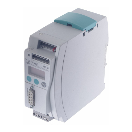
- Page 1 Operating manual PME industrial measurement electronics linked to a field bus MP55 module A0563-7.2 en...
-
Page 3: Table Of Contents
..........Overview of MP55 functions . -
Page 4: Safety Instructions
Intended use The MP55 module with connected transducers is to be used exclusively for measurement tasks and directly related control tasks. Use for any purpose other than the above is deemed to be non‐designated use. - Page 5 General dangers of failing to follow the safety instructions The MP55 module is a state of the art unit and as such is failsafe. The device may give rise to residual dangers if it is inappropriately installed and operated by untrained personnel.
- Page 6 PME-MP55 Residual dangers The scope of supply and performance of the MP55 covers only a small area of measurement technology. In addition, equipment planners, installers and operators should plan, implement and respond to the safety engineering considerations of measurement technology in such a way as to minimize resi...
- Page 7 (VDE 0411 Part 1). The device must be mounted on a support rail connected to grounded con ductor potential. Both the support rail and the MP55/MP55DP module must be free of paint, varnish and dirt at the point of installation.
- Page 8 PME-MP55 Conversions and modifications The MP55 module must not be modified from the design or safety engineering point of view except with our express agreement. Any modification shall exclude all liability on our part for any damage resulting therefrom. In particular, any repair or soldering work on motherboards is prohibited.
-
Page 9: Introduction
The MP55 module is set up and parameterized via a keyboard and dis play, or by using the PME Assistant. The PME Assistant provides a simple user interface under MS‐Windows for parameterizing the modules (in the... -
Page 10: Selecting Amplifier Settings With Dip Switches
PME-MP55 Selecting amplifier settings with DIP switches NOTE The DIP switches must be set or changed before mounting the PME. The different settings are defined with the DIP switches and can be read out over the display (see chapter 5.3). These are the settings for... - Page 11 PME-MP55 Factory settings: Lower S10, S11 and board: S12 and S5 Upper board: S1 and S2 1 2 3 4 5 6 1 2 3 4 5 6 Analog output 1 2 3 1 2 3 4 5 6 1 2 3 4 5 6...
- Page 12 PME-MP55 S2 S1 Factory settings: *) 2) Bridge type Input range 3 mV/V Full bridge 1 2 3 4 5 6 1 2 3 4 5 6 Switch pos. 1 2 3 4 5 6 1 2 3 4 5 6...
- Page 13 PME-MP55 Synchronization Master 1 2 3 4 5 6 Slave 1 2 3 4 5 6 Fig. 2.4: Setting the amplifier (contd.) Bus termination resistor Toggle switch for the termination resistor (also see page 22) Fig. 2.5: Switch for the CAN Bus termination resistor (basic diagram)
-
Page 14: Mounting/Dismounting Mp55
PME-MP55 Mounting/dismounting MP55 Fig. 3.1: Mounting on a support rail Fig. 3.2: Dismounting CAUTION The support rail must be connected to grounded conductor potential A0563-7.2 en... -
Page 15: Connecting Several Modules
Fig. 3.4: Connecting a flat ribbon cable Several MP55 modules can be connected via a flat ribbon cable. This cable provides the local supply voltage connection and synchronization between the modules. No more than eight modules should be interconnected via a flat rib... -
Page 16: Connection
PME-MP55 Connection WARNING Comply with the safety instructions before starting up the device. 4.1 Overview of MP55 functions Local connection of CAN Bus and supply voltage and synchronization between modules, bus termination resistor Plug terminal 1: Voltage supply and CAN Bus,... -
Page 17: Supply Voltage And Control Inputs/Outputs
OUT = digital output For more detailed information on inputs and outputs, see chapter 6, page 38. Should the mains power fail in the MP55 module, all control CAUTION outputs will be set to 0 V. Fig. 4.1: Plug terminal assignment The 4 plug terminals are coded, to prevent confusion when plugging them into the 4 sockets. -
Page 18: External Supply Voltage For Control Outputs
PME-MP55 4.2.1 External supply voltage for control outputs Example: PLC connection MP55 module Relay max. 0.5 A max. 0.5 A OUT3 OUT1 24 V 24 V* 0 V* 0 V* Plug terminal 4 Fig. 4.2: Connection to a PLC The control inputs are available at plug terminal 3, the control outputs at plug terminal 4, and are electrically isolated from the internal supply voltage (also see chapter 6, “Clarification of important parameters", on page 33). -
Page 19: Transducers
PME-MP55 4.3 Transducers The following transducer types can be connected to the MP55 module: Transducer connector socket Strain gage and inductive full Strain gage and inductive half bridges, piezoresistive bridges transducers Measurement Measurement signal (+) signal (+) Bridge excitation Bridge excitation... -
Page 20: Connecting Transducers When Cables Are More Than 50 M Long
For extension cables, use only a six‐wire configuration and use shielded, low‐capacitance measurement cables that are twisted in pairs, such as those from HBM. Attach the shield of the transducer cable to the connector housing in accordance with the HBM Greenline concept, to ensure EMC protection (see HBM Greenline Information, document i1577). -
Page 21: Can Interface
PME-MP55 Sense lead (-) gray Excitation voltage (-) black Measurement signal (-) Excitation voltage (+) blue Sense lead (+) green Measurement signal (+) white Shield U10M Cable extension MP55 (six‐wire configuration) (six‐wire configuration) Fig. 4.5: Transducer connection for cables more than 50 m long; example with U10M force transducer (transducer in a six‐wire circuit) -
Page 22: Synchronization
PME-MP55 is two. A termination resistor is integrated into the MP55 module, and is activated by toggle‐switch S14 (see page 13). Low High 1st device Fig. 4.7: CAN interface connection CAN High CAN Low connection as per Fig. 4.7 First device in... - Page 23 PME-MP55 Synchronization prevents differences in the carrier frequency causing distur bing superpositions. Slave Master 1 2 3 4 5 6 1 2 34 5 6 Fig. 4.9: Setting synchronization When synchronizing several modules, one device must be declared the master. The other devices must be set as slaves.
-
Page 24: Setting And Operating (Mp55)
PME-MP55 Setting and operating (MP55) 5.1 Operating philosophy Display in measuring mode: Measured value -18.0024 Status field Unit ↓ ↑ Flashes in the status field if the parameter value can be edited The keys are pressure‐sensitive: Keep key pressed - value runs continuously (press harder to run faster) - Page 25 PME-MP55 Measuring mode Password status inactive Password status active (factory setting): SET 2 secs SET 2 secs DIALOG PASSWORD Setting mode Enter password: Password ↓ ↑ Input mode Enter required password (factory setting 0) Confirm Example: Enter numerical Select table...
- Page 26 PME-MP55 During measurement, if you press , the following will be displayed: 1. display mode 2. status of input and output 3. kinds of error (ERROR) The symbols also appear in the status field. Measured -18.0024 value Status field Unit...
-
Page 27: Starting Up
If the error message HardwOvf is displayed, please continue reading in chapter 8, “Error messages". In addition to this, the green LED shows you that the MP55 is ready for mea surement. If the LED glows yellow or red, please also continue reading in chapter 8, “Error messages". -
Page 28: Overview Of All Groups And Parameters
5.3 Overview of all groups and parameters Groups TRANSD.‐ ANALOG‐ LIMIT VAL. ADDITION FUNC DIALOG DATA SET DISPLAY TRANSDUCER CONDITIONING PEAK STORE IN/OUT CAN‐BUS CALIBRAT. OUTPUT 1...4 TION Password Recall ? DecPoint Unit P1Meas.? >0<set ? Source Ua Operatn. Operatn. Output1 Baudrate AmplType... -
Page 29: Setting All Parameters
↓ ↑ Flashes, if parameter value can be edited I.PStore press Confirm entry: I.I/O +/- = I.CAN 2 secs Back to measuring mode: I.AddFnc Note: If a group cannot be selected, check under DIALOG to establish Back to whether the group is enabled. MAINGRP PME MP55 A0515‐8.2 en... - Page 30 Groups A0515-8.2 en TRANSD.- Display LimVal.1 TRANSDUCER CALIBRAT CONDITIONING ANALOG OUTPUT Unit ↓ ↑ ↓ ↑ ↓ ↑ ↓ ↑ P1Meas.? >0<set ? SourceUa ↓ ↑ GrosValu NetValue Preset with DIP StoreMax ↓ ↑ switches S1 and S12 >0< StoreMin 0.00 BrdgeTyp fixed w.
- Page 31 Groups Analog output CAN Bus LIMIT VAL.1 LIMIT VAL.2...4 IN/OUT PEAK STORE LimVal.1 ↓ ↑ LimVal.2 LimVal.3 ↓ ↑ Operatn. LimVal.4 ↓ ↑ Output1 Operatn. Motion Error relevant inactiv for 1...4 GrosValu ↓ ↑ Source Input.Min NetValue ↓ ↑ GrosValu ↓...
- Page 32 PME MP55 Groups A0515-8.2 en In/Out CAN‐Bus ADDITION.‐FUNCTION MEAS. MODE ↓ ↑ AmplType Save ? 10kB ↓ ↑ Baudrate 20kB 50kB 100kB 125kB PrgVers 250kB 500kB 1000kB Meas.val. ↓ ↑ ↓ ↑ Address 0.00000 >0<Rf kN ↓ ↑ ↓ ↑...
-
Page 33: Clarification Of Important Parameters
PME-MP55 Clarification of important parameters Group Parameter Meaning DIALOG Password Specify (change) password, 0000 - 9999 (factory settings password: 0000) PassStat Specify password status: active = password must be entered; inactive = PME can be operated without entering a password I.DataS to... - Page 34 PME-MP55 TRANSD.‐ P1Meas.? Transferring the signals supplied by the transducer at a defined loading CALIBRAT P1 mV/V Example:A calibration weight of 4 kg is used to P1 (physi calibrate Physic. cal unit) a 10 kg load cell unit 1. Relieve load on transducer P1Meas.? YES...
- Page 35 PME-MP55 Filter 0.05 Hz 1 Hz 20 Hz 500 Hz 0.1 Hz 2 Hz 50 Hz 0.2 Hz 5 Hz 100 Hz 0.5 Hz 10 Hz 200 Hz FiltChar Step response The diagram shows a linear amplitude response with a steep drop above the cut‐off frequency.
- Page 36 PME-MP55 Group Parameter Meaning ANALOG Source UA The gross or net value, as well as the peak value, can be OUTPUT chosen as the source of the analog signal. Mode UA Use DIP switches S11 and S5 to specify the signal mode for the analog output.
- Page 37 PME-MP55 Group Parameter Meaning LIMIT VAL. Source The choice of source for the limit value signal is: gross, net, 1...4 peak value max/min/peak‐to‐peak SwtchDir Limit value functions and parameters Value Limit1, ON Value Hyst Over limit Hyst Under limit Hyst...
- Page 38 PME-MP55 Inputs /outputs Plug terminal 3: Here there are 4 inputs available to you for controlling the functions of the PME. Plug terminal 4: Here there are 4 outputs available. Group Parameter Meaning IN/OUT Output 1...4 Outputs 1 - 4 can be assigned the following...
- Page 39 PME-MP55 Group Parameter Meaning IN/OUT PkMom Peak value operating mode Measurement signal PkMomMin PkHldMax Stored value PkHldMax response PkHldMin Hold Hold Function Mode of Peak value (Store1) Current value operation Current value operating mode Measurement signal Hold Function Mode of...
- Page 40 PME-MP55 Group Parameter Meaning ADD. >0<Rf Reference zero A displacement transducer 〈"20 mm nominal (rated) FUNCTION displacement) is mounted at a height of 1 m, measured from the foundation. When zeroing, the analog output is adjusted to 0 V. The display value is adjusted to >0<Ref (+1000 mm).
-
Page 41: Can Interface Description
CAN interface description 7.1 General The MP55 module has a built‐in CAN interface, which can be used both for transmitting measured values and for module parameterization. Different baud rates can be selected up to a maximum of 1 MBaud. The interface protocol is adapted from the CANopen Standard. -
Page 42: Parameterization
Á Á Á Á Á Á Á Á Á Á Á Á Á Á Á Writing a parameter: Transmit value (PC or PLC to MP55) Á Á Á Á Á Á Á Á Á Á Á Á Á Á Á Á Á Á Á Á Á Á Á Á... - Page 43 Á Á Á Á Á Á Á Á Á Á Á Á Á Á Á Response in the event of an error when reading or writing parameters: Error acknowledgement (MP55 to PC or PLC) Á Á Á Á Á Á Á Á Á...
-
Page 44: Object Dictionary: Communication Profile Range In Accordance With Canopen (Cia-Ds301)
PME-MP55 7.4 Object dictionary: Communication profile range in accordance with CANopen (CiA‐DS301) Á Á Á Á Á Á Á Á Á Á Á Á Á Á Á Á Á Á Á Á Á Á Á Á Á Á Á Á... - Page 45 PME-MP55 Á Á Á Á Á Á Á Á Á Á Á Á Á Á Á Á Á Á Á Á Á Á Á Á Á Á Á Á Á Á Á Á Á Á Á Á Á Á Index Sub‐...
- Page 46 PME-MP55 SDO parameters: Á Á Á Á Á Á Á Á Á Á Á Á Á Á Á Á Á Á Á Á Á Á Á Á Á Á Á Index Sub‐index Name Data type Á Á Á Á Á Á Á Á Á...
-
Page 47: Object Dictionary: Manufacturer-Specific Objects
PME-MP55 7.5 Object dictionary: manufacturer‐specific objects Parameters that make reference to measured values are scaled true to num ber, coded as Long (32‐bit integer). The position of the decimal point is defined in object 2120 Hex. Alternatively, these quantities are also available as Float values (IEEE754‐1985 32‐bit format). - Page 48 PME-MP55 Á Á Á Á Á Á Á Á Á Á Á Á Á Á Á Á Á Á Á Á Á Á Á Á Á Á Á Á Á Á Á Á Á Á Á Á Á Á Index Sub‐...
- Page 49 PME-MP55 Á Á Á Á Á Á Á Á Á Á Á Á Á Á Á Á Á Á Á Á Á Á Á Á Á Á Á Á Á Á Á Á Á Á Á Á Á Á Index Sub‐...
- Page 50 PME-MP55 Á Á Á Á Á Á Á Á Á Á Á Á Á Á Á Á Á Á Á Á Á Á Á Á Á Á Á Á Á Á Á Á Á Á Á Á Á Á Index Sub‐...
- Page 51 PME-MP55 Á Á Á Á Á Á Á Á Á Á Á Á Á Á Á Á Á Á Á Á Á Á Á Á Á Á Á Á Á Á Á Á Á Á Á Á Á Á Index Sub‐...
- Page 52 PME-MP55 Á Á Á Á Á Á Á Á Á Á Á Á Á Á Á Á Á Á Á Á Á Á Á Á Á Á Á Á Á Á Á Á Á Á Á Á Á Á Index Sub‐...
- Page 53 PME-MP55 Á Á Á Á Á Á Á Á Á Á Á Á Á Á Á Á Á Á Á Á Á Á Á Á Á Á Á Á Á Á Á Á Á Á Á Á Á Á Index Sub‐...
- Page 54 PME-MP55 Á Á Á Á Á Á Á Á Á Á Á Á Á Á Á Á Á Á Á Á Á Á Á Á Á Á Á Á Á Á Á Á Á Á Á Á Á Á Index Sub‐...
- Page 55 PME-MP55 Á Á Á Á Á Á Á Á Á Á Á Á Á Á Á Á Á Á Á Á Á Á Á Á Á Á Á Á Á Á Á Á Á Á Á Á Á Á Index Sub‐...
-
Page 56: Manufacturer-Specific Objects In Float Data Format
PME-MP55 7.6 Manufacturer‐specific objects in FLOAT data format Á Á Á Á Á Á Á Á Á Á Á Á Á Á Á Á Á Á Á Á Á Á Á Á Á Á Á Á Á Á Á Á Á Á Á Á Á Á... - Page 57 PME-MP55 Á Á Á Á Á Á Á Á Á Á Á Á Á Á Á Á Á Á Á Á Á Á Á Á Á Á Á Á Á Á Á Á Á Á Á Á Á Á Index Sub‐...
-
Page 58: Examples
PME-MP55 7.7 Examples Example 1: Reading the net measured value as a float value via SDO transfer from the amplifier with module address 3. Protocol to the amplifier: Á Á Á Á Á Á Á Á Á Á Á Á Á Á... - Page 59 PME-MP55 Example 3: The tare value is to be set to 23.250 kg (transfer as a long value, i.e. 23.250 =23250). Assumed settings: unit “kg", decimal places: 3 Protocol to the amplifier: Á Á Á Á Á Á Á Á Á Á...
-
Page 60: Error Messages/Operating State (Led)
PME-MP55 Error messages/operating state (LED) Depending on the display mode, various error messages can appear on the display instead of the measured value: Signal status (mode) Possible error message HrdwOvfl ADC+Ovf Grs+Ovfl Scal.Err - - - - - - -... - Page 61 PME-MP55 Current errors are displayed continuously (also see page 26). Press , until you arrive at “ERROR" display mode. Error message Cause Remedy Hrdware Input signal overflow Transducer not connected Connect transducers, 2)5) (HrdwOvfl) Incorrect transducer connection see pin assignment on page 19...
- Page 62 PME-MP55 Operating state: LED color Status Meaning Measuring mode Bus mode Green Steady light Ready for measurement CAN Operational (PDO trans fer possible) Green Flashes Data being transmitted over the interface Yellow Steady light Ready for measurement CAN Bus PreOperational...
-
Page 63: Index
Index Index Dialog, 48 Additional functions, 40, 53 Digital input, 17 Additional spring, 15 Digital inputs/outputs, 54 Address, 39 Digital output, 17 Amplifier settings, 10 DIP switch, 10 Analog output, 11, 12, 16, 17, 36, 51, 56 Discharge rate, 37 Dismounting, 14 Display adaptation, 49 Baud rate, 39... - Page 64 Index LED, 62 Recall, 33 level, 37 Reference zero, 40 Limit value, 37 Remote controls, 38 Limit value level, 37 Limit value switch, 52, 57 Save, 33 Scale factor, 36 Mains power failure, 17 Scaling, 33, 36 Measured value, 47, 56 Scaling factor, 33 Measuring mode, 25 Scaling range, 36...
- Page 65 Index Zero offset, 34 Zero value, 34 Zero balance, 34 A0563-7.2 en...
- Page 66 Index A0563-7.2 en...
- Page 68 They are not to be understood as express warranty and do not constitute any liability whatsoever. Hottinger Baldwin Messtechnik GmbH Im Tiefen See 45 S 64293 Darmstadt S Germany Tel. +49 6151 803-0 S Fax: +49 6151 803-9100 Email: info@hbm.com www.hbm.com...
Need help?
Do you have a question about the MP55 and is the answer not in the manual?
Questions and answers