Table of Contents
Advertisement
Available languages
Available languages
Quick Links
Advertisement
Chapters
Table of Contents

Related Manuals for HBM MP55


Summary of Contents for HBM MP55
- Page 1 Bedienungsanleitung Operating manual Interbus-S Interface MP55IBS A0822-2.1 de/en...
- Page 2 Deutsch ..........Seite 3 −...
-
Page 3: Table Of Contents
PME-MP55IBS Inhalt Seite Einführung ..........Anschließen . -
Page 4: Einführung
PME−MP55IBS Einführung In dieser Bedienungsanleitung werden nur diejenigen Funktionen beschrie- ben, die vom MP55 abweichen. Die Funktionalität des MP55IBS entspricht der des MP55. Der TF-Verstärker MP55 ist um eine Interbus-S-Schnittstelle ergänzt worden. Die Funktionalität auf der CAN-Schnittstelle bleibt erhalten; das Objektver- zeichnis wird um einige Parameter der Interbus-Kopplung erweitert. -
Page 5: Anschließen
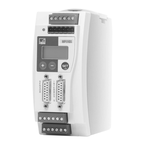
PME−MP55IBS Anschließen WARNUNG Beachten Sie vor der Inbetriebnahme des Gerätes die Sicherheitshinweise. 2.1 Anschlussbelegung Auf der Frontseite des MP55IBS befindet sich eine zusätzliche 15-polige D-Sub-Anschlussbuchse für den Anschluss des Interbus-S. Mit dem im Liefer- umfang enthaltenen Adapterkabel kann eine normgerechte Verbindung aufge- baut werden. - Page 6 PME−MP55IBS Pin-Belegung Interbus-S-Adapter Modul Pin Signal Verbindung Pin− ankommende Verbindung Pin− abgehende (D-Sub15) Schnittstelle Schnittstelle (D-Sub9, Stecker) (D-Sub9, Buchse) nicht belegt − − nicht belegt − − − /DO1 − /DI1 − /RBST − − − GND ext. − − −...
-
Page 7: Bedienen Über Tastatur
PME−MP55IBS Bedienen über Tastatur Die Bedienung der Interbus-S-relevanten Parameter geschieht über die Tasta- tur (Hauptgruppe INTERBUS-S) oder über CANopen-Objekte. Während des Messens können Sie sich − durch Drücken von − im − Display folgende Funktionen ansehen (Messwert, Ausg,Eing; Fehlermeldun- gen). Im Anschluss an die Statusmeldung “FEHLER”... - Page 8 PME−MP55IBS CAN-Objekte Objektlx 2550, Sublx0: Konfiguration festlegen (bitcodiert) Die Dateninhalte sind identisch mit denen des CAN-Bus. Datenobjekte Brutto Netto Spitze−Spitze Status 1 Status 2 reserviert Steuerwort Nullwert reserviert reserviert Objektlx 2551, Sublx0: Datenformat festlegen Format Daten int16 1255 int32 1253 float 1257 Objektlx 2552, Sublx0: Interbus-Statusmeldung anzeigen...
-
Page 9: Erweiterte Menüs
PME−MP55IBS 3.1 Erweiterte Menüs Neue Gruppe “Interbus” im Einstellbetrieb: − Gruppen DIALOG SPITZWRT EIN/AUSG CAN-BUS INTERBUS−S ZUSATZFUNKTION Passwort Freigabe Ausgang1 Baudrate Brutto Verst Typ PassStat Eing.Min Mode Aus1 Adresse Netto PrgVers Sprache Ausgang2 Protokol SpwtMax >0<Rf kN E.ParaS SpLöschn Mode Aus2 Ausgabe SpwtMin StillAnz... -
Page 10: Einstellungen Für Interbus-S
PME−MP55IBS Einstellungen für Interbus-S Das eingestellte Datenformat gilt für alle im zyklischen Datenverkehr ausge- tauschten Messwerte. Die Angabe der Nachkommastellen für die Formate In- teger 16 Bit und Integer 32 Bit wird aus der Modul-Einstellung übernommen (z.B. 2.0 mm wird bei Vorgabe von 3 Nachkommastellen als Integer-Wert 2000 übertragen). -
Page 11: Konfiguration
PME−MP55IBS 4.1 Konfiguration Die Konfiguration legt fest, welche Dateninhalte im zyklischen Datenverkehr ausgetauscht werden. Für die Auswahl stehen folgende Daten zur Verfügung: Eingangswerte: Bezeichnung Bedeutung Länge Brutto Brutto-Messwert 1 oder 2 Worte Netto Netto-Messwert (Brutto abzüglich Tara-Wert) 1 oder 2 Worte Inhalt des Maximum-Speichers 1 oder 2... -
Page 12: Zyklischer Datenaustausch
PME−MP55IBS 4.2 Zyklischer Datenaustausch Abhängig von der Konfiguration werden folgende Dateninhalte ausgetauscht: 4.2.1 Eingänge (vom MP55IBS an die SPS gesendet) Messwerte Messwerte können in unterschiedlicher Darstellung übertragen werden. Zur Auswahl stehen Float (2 Worte, 32Bit), 16 Bit Festpunktzahl (1 Wort, 16 Bit In- teger im Zweierkomplement, Kommastelle muss der lesenden Stelle bekannt sein) oder 32 Bit Festpunktzahl (2 Worte, 32 Bit Integer im Zweierkomple- ment, Kommastelle muss der lesenden Stelle bekannt sein). -
Page 13: Ausgänge (Von Der Sps An Den Mp55Ibs Gesendet)
PME−MP55IBS Die Parametersatznummer ist in 2 Bit binär kodiert: Bit 8 Bit 9 Parametersatz-Nr. Status 2 Das Status-Doppelwort 2 liefert eine detailliertere Fehlerkennzeichung. Name Bedeutung HardwOvfl Übersteuerung Hardware ADCOvfl ADC übersteuert GrossOvfl Bruttosignal übersteuert NetOvfl Nettosignal übersteuert AOutOvfl Analogausgang übersteuert MaxOvfl Maximum übersteuert MinOvfl... - Page 14 PME−MP55IBS Steuerwort Name Bedeutung NULL 0−1 löst autom. Nullstellen aus 0−1 löst Tarierung aus CLRMAX 0−1 löscht den Spitzenwertspeicher MAX CLRMIN 0−1 löscht den Spitzenwertspeicher MIN HOLDMAX 1: Spitzenwertspeicher MAX einfrieren HOLDMIN 1: Spitzenwertspeicher MIN einfrieren PAR1 Parametersatz-Auswahl Bit 1 PAR2 Parametersatz-Auswahl Bit 2 10..15...
- Page 15 PME-MP55IBS Contents Page 1 Introduction ..........2 Connections .
-
Page 16: Introduction
Introduction This Operating Manual describes only those functions which differ from the MP55. The features of the MP55IBS correspond to those of the MP55. The MP55 carrier-frequency amplifier has been expanded to include an Interbus-S interface. The features on the CAN-interface remain the same; the object directory is expanded to include some parameters for the Interbus connection. -
Page 17: Connections
PME−MP55IBS Connections WARNING Please take note of the safety instructions before putting the device into operation. 2.1 Pin assignment On the front panel of the MP55IBS is an additional 15-pin D-sub connection socket for the Interbus-S port. The adapter cable supplied allows a connection to be established in line with the relevant standards. - Page 18 PME−MP55IBS Pin assignment for Interbus-S adapter Module pin Signal Connection pin - incoming Connection pin - outgoing (D-Sub15) interface interface (D-Sub 9, male connector) (D-Sub 9, female connector) No function − − No function − − − /DO1 − /DI1 −...
-
Page 19: Operation Via The Keyboard
PME−MP55IBS Operation via the keyboard The parameters relevant to Interbus-S are handled via the keyboard (main group INTERBUS-S) or by using CANOpen objects. During measurement you can press − to view the status messages in − the display (Measuring value, Output, Input; error messages). Next to the status message “ERROR”... - Page 20 PME−MP55IBS CAN objects Objektlx 2550, Sublx0: Define configuration (bit-coded) The data contents are the same as for the CAN bus. Bits Data objects Gross Peak-to-peak Status 1 Status 2 Reserved Control word LVS1 LVS2 LVS3 LVS4 Zero value Reserved Reserved Objektlx 2551, Sublx0: Define data format Format Data...
-
Page 21: Expanded Menus
PME−MP55IBS 3.1 Expanded menus New “Interbus” group in set-up mode: − Groups ADDITION DIALOGUE PEAK STORE IN/OUT CAN-BUS INTERBUS-S FUNCTION Password Operatn. Output1 Baud rate Gross AmplType PassStat InputMin ModeOut1 Address PrgVers Output2 Protocol PkValMax >0<Rf kN Language I.DataS ClearPkV ModeOut2 Output PkValMin... -
Page 22: Setup For Interbus-S
PME−MP55IBS Setup for Interbus-S The defined data format applies to all the measured values exchanged in the cyclical data communication. The definition of the decimal places for the formats integer 16 bits and integer 32 bits is adopted from the module setting (e.g. -
Page 23: Configuration
PME−MP55IBS 4.1 Configuration The configuration defines which data contents are exchanged in the cyclical data communication. The following data is available for selection: Input values: Name Meaning Length Gross Gross measured value 1 or 2 words Net measured value (gross minus tare value) 1 or 2 words Contents of the maximum store... -
Page 24: Cyclical Data Exchange
PME−MP55IBS 4.2 Cyclical data exchange Depending on the configuration, the following data contents are exchanged: 4.2.1 Inputs (from MP55IBS to the PLC) Measured values Measured values can be communicated in various forms of representation. The forms of representation available for selection are floating (2 words, 32 bit), 16 bit fixed point number (1 word, 16 bit integer in two’s complement, decimal place must be known to the reader) or 32 bit fixed point number (2 words, 32 bit integer in two’s complement, decimal place must be known to... -
Page 25: Outputs
PME−MP55IBS The parameter set number is coded in 2 bit binary: Bit 8 Bit 9 Parameter set no. Status 2 Double status word 2 returns detailed error flagging. Bits Name Meaning HardwOvfl Hardware overflow ADCOvfl ADC overflow GrossOvfl Gross signal overflow Net-Ovf Net signal overflow AOutOvfl... - Page 26 PME−MP55IBS Control word Bits Name Meaning ZERO 0−1 autom. triggers zeroing 0−1 triggers taring CLRMAX 0−1 clears the MAX peak-value store CLRMIN 0−1 clears the MIN peak-value store HOLDMAX 1: freeze MAX peak-value store HOLDMIN 1: freeze MIN peak-value store PAR1 Parameter set selection bit 1 PAR2...
- Page 28 7−2001.0822 Hottinger Baldwin Messtechnik GmbH Postfach 10 01 51, D-64201 Darmstadt Im Tiefen See 45, D-64293 Darmstadt Tel.: +49 6151 803-0 Fax: +49 6151 8039100 Email: support@hbm.com Internet: www.hbm.com A0822−2.1 de/en...
Need help?
Do you have a question about the MP55 and is the answer not in the manual?
Questions and answers