Table of Contents
Advertisement
Quick Links
Advertisement
Table of Contents

Related Manuals for HBM MXFS


Summary of Contents for HBM MXFS
- Page 1 User Manual English MXFS QuantumX BraggMETER Module...
- Page 2 Tel. +351 229 613 010 Fax +351 229 613 020 fibersensing@hbkworld.com www.hbm.com/fs Mat.: DVS: A05595_02_E00_00 HBM: public 05.2021 E Hottinger Baldwin Messtechnik Subject to modifications. All product descriptions are for general information only. They are not to be understood as a guarantee of quality or...
-
Page 3: Table Of Contents
Concepts and definitions ........MXFS A05595_02_E00_00 HBM: public... - Page 4 ......... Starting a project with MXFS .
- Page 5 ......... . MXFS A05595_02_E00_00 HBM: public...
-
Page 6: Technical Details
Technical details Technical details General Information The MXFS is a module from the Quantum X family for measuring Fiber Bragg Grating (FBG) based sensors. It is based on the well-established BraggMETER technology from HBK FiberSensing, that employs a continuous swept laser scanning for measuring reflected Bragg peaks. It includes a traceable wavelength reference that provides continuous calibration to ensure system accuracy over long term operation. -
Page 7: System Components
Power adapter 1-KAB239-2 Ethernet crossover cable 2 m Software As for the remaining QuantumX modules, MXFS is an open data acquisition system, and can be integrated into a great many operating, analysis and auto mation software packages. Available for download are: S MX Assistant and Common API: modern and free device assistants that support the module acquisition and data functions. -
Page 8: Synchronization
MXFS without any extra cost. S Drivers for LabView S Windows device driver for IEEE1394b FireWire Synchronization MXFS follows the available synchronization methods of the QuantumX family: S NTP S PTPv2 S EtherCAT (via CX27) S IRIG-B (via MX440B or MX840B) -
Page 9: Regulatory And Certification Considerations
HBK FiberSensing to Amb3E. Laser Safety The MXFS Interrogator contains a laser in its core. A laser is a light source that can be dangerous to people exposed to it. Even low power lasers can be haz ardous to a person's eyesight. The coherence and low divergence of laser light... -
Page 10: Symbols
2.2.2 Class 1 Laser The MXFS is a Class 1 laser product: «Any laser or laser system containing a laser that cannot emit laser radiation at levels that are known to cause eye or skin injury during normal operation.» It is safe under all conditions of normal use. -
Page 11: Certification
S Electromagnetic Compatibility (EMC) Directive 2014/30/EU The corresponding Declaration of Conformity is available upon request. 2.2.5 Marking of pollutant emission limit values (for deliveries to China) Statutory marking of compliance with emission limits in elec tronic equipment supplied to China. MXFS A05595_02_E00_00 HBM: public... -
Page 12: Operation
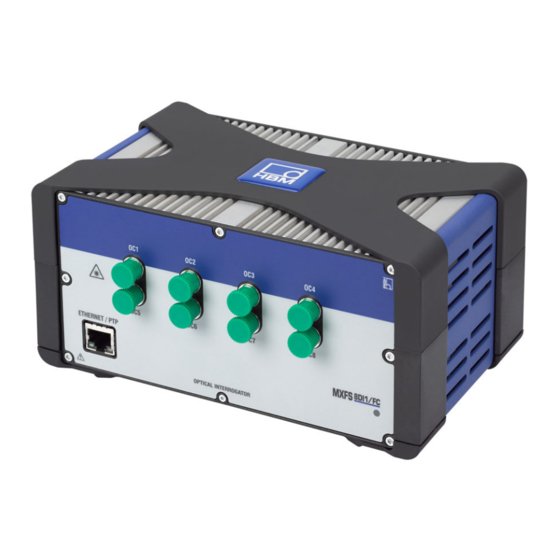
Operation Operation Connectors Fig. 3.1 Front and back view of the MXFS Optical Connectors (FC/APC) Ethernet Connectors STATUS LED Power connector Firewire connectors Backplane connector MXFS A05595_02_E00_00 HBM: public... -
Page 13: Setting Up
Power supply Connect the modules to a DC voltage of 18 V ... 30 V (24 V recommended). The power consumption of one MXFS module is < 30 W. Important The following rule of thumb applies to power distribution via FireWire: “An external voltage supply with the same voltage potential is required on... -
Page 14: Connection To Pc Or Data Recorder
KAB271-3 KAB272 FireWire Fig. 3.2 Connecting options for power supply 3.2.2 Connection to PC or data recorder 3.2.2.1 Single Ethernet connection 10 V … 30 V DC KAB293-2 TCP/IP, 100 Mbps Fig. 3.3 Single Ethernet connection MXFS A05595_02_E00_00 HBM: public... -
Page 15: Multiple Ethernet Connection With Ptp Synchronization
Modules can be connected to the PC via Ethernet PTPv2‐compliant switches. We recommend patch cables. Here are some examples: S EX23-R from HBM S Scalance XR324-12M from Siemens S RSP20 or MACH1000 from Hirschmann S Ha-VIS FTS 3100-PTP from Harting... -
Page 16: Multiple Ethernet Connection And Firewire Synchronization
(max. 1.5 A through FireWire; for power consump tion of the modules, see chapter 3.2.1 “Power supply”, page 13). Advantage of this connection structure: The other modules remain active if the Ethernet cable is broken. MXFS A05595_02_E00_00 HBM: public... -
Page 17: Other Possible Connections
Operation 3.2.2.4 Other possible connections There are several other possibilities of connection between MXFS modules or MXFS and other QuantumX modules: S Connection of a single module via FireWire S Connection of several modules via FireWire S Connection to a CX22 data recorder... - Page 18 172.21.108.51 255.255.248.0 Module after 172.21.108.1 255.255.248.0 The first three digit groups of the PC and module IP addresses should be the same. The subnet mask address digit groups must be identical in the module and PC! MXFS A05595_02_E00_00 HBM: public...
- Page 19 Example of settings for a direct connection Ethernet settings: adjust the IP address of your PC If you want to operate the modules with a fixed, static IP address, you should use the Alternative Configuration (fixed IP address and subnet mask, MXFS A05595_02_E00_00 HBM: public...
- Page 20 Configuration in the TCP/IP properties (fixed IP address and subnet mask, user-defined)! ► On the control panel choose Network Connections ► Select the LAN connection. The window displayed in Fig. 3.7 will appear. Click on Properties. Fig. 3.7 Network properties MXFS A05595_02_E00_00 HBM: public...
- Page 21 Operation ► Select the Internet Protocol (TCP/IP) and click on the Properties button (Fig. 3.8). Fig. 3.8 TCP/IPv4 MXFS A05595_02_E00_00 HBM: public...
- Page 22 Operation ► Set the IP address and the Subnet mask (Fig. 3.9). Fig. 3.9 IP and Subnet ► Press OK. MXFS A05595_02_E00_00 HBM: public...
-
Page 23: Firmware Update
We recommend that the firmware and software used to operate QuantumX are always kept up to date. ► Download the latest firmware from the HBM website. If you do not work with catman, please download the QuantumX software package from the HBM website. -
Page 24: Status Indicators
Please refer to the generic Quantum X user manual (document A03031 available for download on our website) for further options on updating the module’s firmware if not using catman. Status indicators Fig. 3.11 MXFS front view MXFS A05595_02_E00_00 HBM: public... -
Page 25: Factory Reset
Download active, system is not ready - Firmware upgrade Error Factory reset It is possible to reset the MXFS module to its factory settings which will delete the configuration in use by the device: S Deactivates all channels S Deletes all configured bands... -
Page 26: Connecting To Optical Sensors
3.5.1 Concepts and definitions 3.5.1.1 Connectors The MXFS has 8 FC/APC optical connectors located on its front panel (see Fig. 3.1). The device is ready to receive several Fiber Bragg Grating (FBG) sensors connected in series on the same optical fiber. - Page 27 Ranges cannot overlap. A measurement is only taken when a fiber Bragg grating peak is found inside the range. If no peak is found inside a defined range an overflow value is given. MXFS A05595_02_E00_00 HBM: public...
-
Page 28: Wavelength
The reference wavelength is, for non calibrated sensors, the zero value of the measurement. For calibrated sensors, the reference wavelength should be defined as stated on their calibration sheets. MXFS A05595_02_E00_00 HBM: public... -
Page 29: Power
Wavelength value of the FBG peak at each acquired sample. 3.5.1.4 Power The power value corresponds to the optical power reflected by the fiber Bragg grating at peak wavelength. Fig. 3.15 Power Power axis, in dBm FBG reflected spectrum FBG peak Power value in dBm MXFS A05595_02_E00_00 HBM: public... -
Page 30: Dynamic Range
Bragg grating can be correctly identified and mea sured. Fig. 3.16 Dynamic Range Power axis, in dBm Wavelength axis, in nm FBG reflected spectrum Maximum measurable power Minimum measurable power Dynamic Range, in dB MXFS A05595_02_E00_00 HBM: public... -
Page 31: Smart Peak Detection (Spd)
FBG peak inside each configurable band. MXFS considers a fixed threshold value of 3 dB, easing the configuration of the device (Fig. 3.17). Every wavelength value is calculated considering the area of the FBG peak above half its power. - Page 32 FBGs coexist and signal losses are often a problem. SPD therefore improves the stability and accuracy of the measurements, contributing to the system's efficiency, even at high acquisition speeds. MXFS A05595_02_E00_00 HBM: public...
-
Page 33: Signals
Measured wavelength within the channel (λ), in nm Wavelength variation within the channel, in nm. If the peak falls out of the defined bands for the channel, an overflow value is presented. The wavelength variation relates to the signals via conversion factors. MXFS A05595_02_E00_00 HBM: public... - Page 34 MXFS signals have a one to one relationship with the FBG peak. This means that complex sensors that use more than one FBG, or computations performed using values from two FBG are not possible to be performed within the device.
-
Page 35: Acquisition Rate
Operation Acquisition rate 3.6.1 Speed mode MXFS operates with two different speed modes that correspond to two sweeping laser speeds: S High Speed mode: 2000 S/s S Low Speed mode: 100 S/s Information Changing the speed mode will restart the device. - Page 36 DutyCycle is a constant for the acquisition period (0.84 for BraggMETER interrogators); c is the speed of light (3·10 m/s). This means that for MXFS, the shift in wavelength is given by a function of the distance and the acquisition rate defined on the interrogator: MXFS A05595_02_E00_00 HBM: public...
- Page 37 Operation Wavelength shift due to sweeping laser speed in MXFS Δλ + 2 @ 1.446 @ 104 @ d @ RepRate + 1.1585 @ 10 @ d @ RepRate 0.84 @ 3 @ 10 Next tables aim to illustrate the difference in a sensor readout (wavelength shift in pm) caused by the distance between the Interrogator and the sensor for the different devices and options.
-
Page 38: Filters
In catman use a computational channel to get the distance correction. 3.6.3 Filters MXFS supports low-pass filtering, as any other QuantumX Module. Available filters are Bessel, Butterworth, linear phase. Please check chapter 4.2.1.2 “Sampling rate and filters”, page 47 for more details. -
Page 39: Measurement Troubleshooting
Magnified view of a clean and a dirty connector The most common effect of dirt on the connections is a large amount of broad band light being reflected at the connection, in both directions, meaning that the dynamic range for measurements becomes smaller. MXFS A05595_02_E00_00 HBM: public... - Page 40 To clean an optical interrogator adapter, use an appropriate cotton swab (there are several cleaning swabs in the market frequently used for telecom fibers) embedded in isopropyl alcohol. Insert it in the optical adapter as in Fig. 3.22 and rotate the swab always in the same direction. MXFS A05595_02_E00_00 HBM: public...
-
Page 41: Broken Connector
A broken sleeve will look as shown in Fig. 3.23. Fig. 3.23 Broken connector To solve this problem you should contact HBK FiberSensing. MXFS A05595_02_E00_00 HBM: public... -
Page 42: Catman Software
Operation catman software MXFS includes one license for catman Easy software which should be used to configure the device. MXFS is compatible with catman versions 5.4.1 or above. Starting a project with MXFS ► Launch catman software. ► On the start menu select a QuantumX/SomatXR the device type. -
Page 43: Synchronization
Fig. 4.2 Connectivity ► Start a new measurement project Information MXFS gateway functionality is not supported in catman. Please switch it off with MX Assistant before using MXFS with catman. 4.1.1 Synchronization Different synchronization methods for MXFS are available. Please refer to catman user manual (A05566) for more details on how to setup these. -
Page 44: Catman Project For Mxfs
Operation Catman project for MXFS When a new project is started with an MXFS device, catman starts by populating the channel list with all channels from MXFS (128). Fig. 4.3 DAQ channels Channels that have defined bands - ranges of wavelength - on the device are seen as active and non defined channels are seen as inactive. - Page 45 Operation Fig. 4.4 Hiding inactive channels MXFS A05595_02_E00_00 HBM: public...
-
Page 46: Sample Rates
Operation 4.2.1 Sample rates 4.2.1.1 Acquisition rate MXFS operates with two different speed modes that correspond to two sweeping laser speeds, which can be set in catman: S High Speed mode: 2000 S/s S Low Speed mode: 100 S/s Fig. 4.5 Acquisition rate ►... -
Page 47: Sampling Rate And Filters
Regardless of the acquisition speed down sampling and filtering is available on the module, as any other QuantumX module. Available sampling rates and filters are: Low speed mode (100 S/s) Filter cut-off Available sample rates frequency (Hz) MXFS A05595_02_E00_00 HBM: public... -
Page 48: Configuring Ranges Of Wavelength
Configuring ranges of wavelength To configure the bands (ranges of wavelength for each channel) ► Press the configure ranges button available on the top ribbon of catman to open the configure ranges window. Fig. 4.6 Configure ranges button MXFS A05595_02_E00_00 HBM: public... - Page 49 Fig. 4.7 Ranges configuration window Visualization and band editing must be performed one connector at a time: ► Change the selected connector on the connector box (Fig. 4.8) MXFS A05595_02_E00_00 HBM: public...
-
Page 50: Automatically Define Bands For The Detected Peaks
Automatic band detection will detect a peak and define the possible range of wavelength centered at the peak (number in Fig. 4.9), with half band width to each side (number in Fig. 4.9). MXFS A05595_02_E00_00 HBM: public... - Page 51 Operation Fig. 4.9 Automatic band definition On the bottom of the window ► Define band width, in nm. The band width corresponds to the full wave length range of the channels. ► Press Create. MXFS A05595_02_E00_00 HBM: public...
- Page 52 ► Writing on the table the minimum band value, maximum band value and reference wavelength - number in Fig. 4.11 -, or ► Adjusting the minimum band value, maximum band value and reference wavelength with the scroll bars at the bottom - number in Fig. 4.11. MXFS A05595_02_E00_00 HBM: public...
- Page 53 ► Press Apply for the changes to be transferred to the device (Fig. 4.12). Fig. 4.12 Apply definitions to the device MXFS A05595_02_E00_00 HBM: public...
-
Page 54: Individually Define Bands By Hand
Create band in this place. This will define a band centered at the clicked pixel, with the defined settings for the automatic detection of bands, for the selected channel. MXFS A05595_02_E00_00 HBM: public... - Page 55 Operation Fig. 4.13 Editing or creating bands When all the desired bands are defined, click on Apply button and close the configuration window. MXFS A05595_02_E00_00 HBM: public...
-
Page 56: Sensors On The Device
There are different types of sensors that can be configured into the device (for more details please refer to section 3.5.1.7 “Signals”, page 33). ► Double-click on the Sensor/Function column for changing or configuring sensors into the device MXFS A05595_02_E00_00 HBM: public... -
Page 57: Sensors On The Software
Operation 4.2.4 Sensors on the software Optical sensors are available on catman database under General Sensors. Fig. 4.15 Optical sensors on sensors database MXFS A05595_02_E00_00 HBM: public... -
Page 58: Wavelength
Fig. 4.16 Wavelength Absolute and Wavelength Relative sensor types Wavelength Relative is the “raw” value out of MXFS device. That means that it is the wavelength variation of the FBG peak in that channel. No calculation is performed on the signal, as all is processed inside the device (see sec... -
Page 59: Strain
This should be measured after installation. It can be filled by hand or automatically defined by an actual measurement using the Measure button. λ * λ Strain k @ λ MXFS A05595_02_E00_00 HBM: public... - Page 60 The Temperature Cross Sensitivity (TCS) corresponds to the effect of temper ature on the strain sensor, meaning the induced strain to the sensor after installation due to a change of 1°C on its temperature. It is a value given on the sensor’s documentation. MXFS A05595_02_E00_00 HBM: public...
- Page 61 The selected channel for temperature compensation with this method must be a strain channel (ε MXFS A05595_02_E00_00 HBM: public...
- Page 62 This value should be measured after installation. It can be filled by hand or automatically defined by an actual measurement using the Measure button. λ * λ Strain with compensation using a * ε k @ λ compensation FBG MXFS A05595_02_E00_00 HBM: public...
-
Page 63: Temperature
The reference wavelength of the temperature sensor (λ ) must correspond to the reference wavelength stated on the sensor documentation. @ (λ * λ ) ) S @ (λ * λ ) ) S Temperature MXFS A05595_02_E00_00 HBM: public... -
Page 64: Acceleration
This should be measured after installation. It can be filled by hand or automatically defined by an actual measurement using the Measure button. S @ (λ * λ Acceleration MXFS A05595_02_E00_00 HBM: public... -
Page 65: Generic Polynomial
The reference wavelength (λ ) can be filled by hand or automatically defined by an actual measurement using the Measure button. Generic optical sensor a @ (λ * λ ) b @ (λ * λ ) ) c MXFS A05595_02_E00_00 HBM: public... - Page 66 ► To zero one or more sensors, select the desired lines and press the Zero balance button on the top ribbon. Fig. 4.23 Zero Balance ► Alternatively, right click on the line to zero and select Zero Balance option (number in Fig. 4.24). MXFS A05595_02_E00_00 HBM: public...
- Page 67 Important Zeroing sensors in catman will create an offset on the sensors configuration at the device level. Zero balance will affect measured values delivered by the device. MXFS A05595_02_E00_00 HBM: public...
- Page 68 Always take extra care upon resetting reference wavelength values. MXFS A05595_02_E00_00 HBM: public...
- Page 69 Operation Reset the device The MXFS interrogator can be reset to its factory settings via catman software. ► Right click over the device name and select Device Reset. Fig. 4.25 Device reset ► Select reset options Fig. 4.26 Device reset options Factory settings for all channels.
- Page 70 Reset channel names will: - change all channel names to its default (<Device Name>_CH_<Connec tor #>-<Channel #>, e.g. MXFS8_CH_2-13 for channel 13, in connector 2 of the device MXFS8) The option activate TEDS is not applicable to MXFS MXFS A05595_02_E00_00 HBM: public...
- Page 71 Operation MXFS A05595_02_E00_00 HBM: public...
- Page 72 HBM Test and Measurement Tel. +49 6151 803-0 Fax +49 6151 803-9100 info@hbm.com measure and predict with confidence...
Need help?
Do you have a question about the MXFS and is the answer not in the manual?
Questions and answers