
Related Manuals for Seastar Solutions DC1000


Summary of Contents for Seastar Solutions DC1000
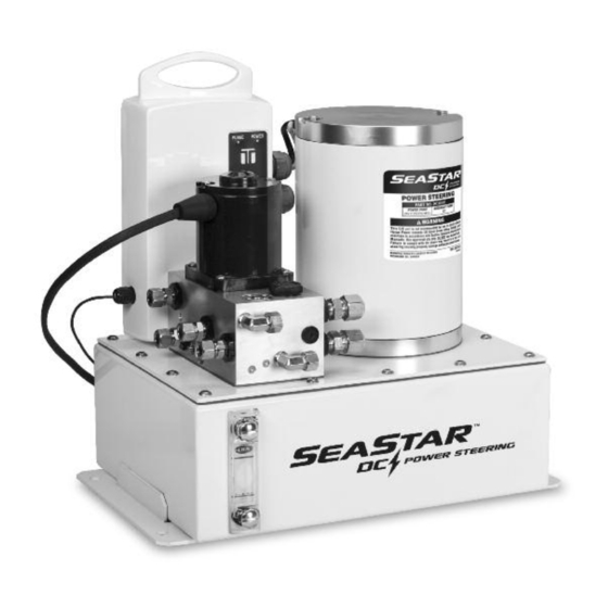
- Page 1 . s e a s t a r s o l u t i o n s . c o m T H I RT Y DC Power Steering Unit ISO 9001 Part # DC1000 & DC2000...
- Page 2 Notice to Boat Manufacturer or Installer Throughout this publication, Warnings and Cautions (accompanied by the International Hazard Symbol ) are used to alert the manufacturer or installer to special instructions concerning a particular service or operation that may be hazardous if performed incorrectly or carelessly.
-
Page 3: Table Of Contents
Before proceeding with the installation, please read these instructions thoroughly to familiarize yourself with the workings of this SeaStar DC Power Steering System. SeaStar Solutions cannot accept responsibility for installations where instructions have not been followed, where substitute parts have been used, or where modifications have been made to our products. -
Page 4: How The System Works
HOW THE SYSTEM WORKS The SeaStar DC Power Unit is a self contained steering system designed to provide an alternative to existing power steering systems. Unlike conventional power steering systems which require engine/pulley driven pumps, oil coolers, oil reservoir, filter and relief control valves, the DC Power Unit is an integrated power steering solution requiring only the DC Power Unit, a steering cylinder and one, or multiple, helm pumps. -
Page 5: Seastar Dc Power Unit Compatibility Chart
DC POWER STEERING UNIT SeaStar DC Power Unit Compatibility The DC Power Unit is compatible with the following SeaStar steering equipment: Helms All 1.4 and 1.7 SeaStar Non-Feedback helms. DC Power Unit is NOT compatible with Hynautic, Capilano, or other manufacturers’ helms. Cylinders 9"... -
Page 6: Tools
DC POWER STEERING UNIT Tools You will need the following tools to complete your installation. • 5/32" and 1/4" Allen keys • Electrical cut and crimp pliers WARNING • Phillips head screw driver • ALL other tools noted in your DO NOT Use Teflon Tape. -
Page 7: System Overview
DC POWER STEERING UNIT System Overview Included with your kit SeaStar DC Power Quad Ring Unit x 1 Seals x 2 90° Elbow Fittings x 2 Bleeder Tube with Clamps x 1 Relief Valve Screws for Relief Valve x 3 Module x 1 Additional items required •... - Page 8 DC POWER STEERING UNIT • Mount DC Power Unit. Refer to page 7 for mounting details. • Install relief module on power steering cylinder. Refer to page 8 for installation details. NOTICE DO NOT mount the DC Power Unit in an area where pump noise may disturb passengers.
-
Page 9: System Installation
For installations with minimal clearance behind unit, it is advised that electrical connections are made prior to mounting the Unit. NOTICE For installations in areas where pump noise may disturb passengers, the use of rubber isolation mounts is recommended. SeaStar Solutions part # HA2222. DC Power Steering System... -
Page 10: Relief Module Installation
5 below. If the NOTICE servo valve block does NOT have these tapped holes contact SeaStar Solutions Technical Support. All cylinders manufactured • Remove fittings from the PRS and TNK ports on the steering during or after January 2008 cylinder servo block if required. -
Page 11: Plumbing The Dc Power Unit
DC POWER STEERING UNIT Plumbing the DC Power Unit WARNING NON VENT CAP Install non-vent plug part TO POWER UNIT 'HT' PORT # HA5432 into ALL helm pump TO POWER UNIT stations on board vessel. Failure 'HT' PORT to properly install non-vent plugs TO POWER UNIT 'HB' PORT can result in loss of steering... - Page 12 DC POWER STEERING UNIT Figure 8. Config. Hose Connection Connect ‘P’ on helm to ‘H2’ on power unit Connect ‘S’ on helm to ‘H1’ on power unit Connect ‘P’ on helm to ‘H1’ on power unit Connect ‘S’ on helm to ‘H2’ on power unit Table 1 Figure 9.
- Page 13 DC POWER STEERING UNIT SEASTAR HELM PUMP AUTOPILOT PUMP 1/2" DASH 8 2000psi SAE 100R SEASTAR OUTBOARD STEERING HOSES AND/OR COPPER TUBING POWER STEERING CYINDER Figure 10. Typical Plumbing Schematic. NOTICE The drawing in figure 10 is used for visual purposes ONLY, refer to page 9 to page 10 for your specific plumbing details.
-
Page 14: Step 2 Electrical Connections
DC POWER STEERING UNIT Step 2 Electrical Connections DC Power Unit Battery Connections NOTICE It is recommended that the DC Power unit be connected directly to a main battery, or other on-board 24-volt power source rated for 90 amps peak using an appropriate fuse or breaker. 1 Remove electronics casing cover by removing the 6 Phillips head WARNING screws. -
Page 15: Ignition Connection
DC POWER STEERING UNIT Ignition Connection NOTICE A minimum wire gauge of 16AWG is recommended for the ignition trigger wire. Length of this wire is not critical. 1 Insert ignition wire through the small strain relief fitting on the electrical enclosure (see figure 11). 2 Connect the ignition wire with a #8 ring connector to the IGN post inside the electrical box. -
Page 16: Step 3 Filling And Purging
DC POWER STEERING UNIT Step 3 Filling & Purging the System Purging Using Fast Purge Kit (HA2266) 1 Fill DC Power Unit tank with SeaStar Steering Fluid to the "FULL" line on sight glass, DO NOT OVERFILL (refer to Figure 15 for location of sight glass). -
Page 17: Purging Using Supplied Bleed Tubing
DC POWER STEERING UNIT Number of Wheel Turns by Installation SYSTEM HC5801-2 HC5803-2 HC5805 SeaStar 1.4 4.3 Turns 5.3 Turns 4.3 Turns SeaStar 1.7 3.6 Turns 4.4 Turns 3.6 Turns Table 2 If your wheel turns are not to within at least a 1/2 turn of the ones shown above, repeat bleeding procedure. - Page 18 DC POWER STEERING UNIT 7 Referring to Table 1 and Figure 13 and starting at your highest helm station, turn the wheel starboard (configuration A) or port (configuration B) until cylinder is fully retracted. If cylinder is already fully retracted, proceed to the next step. 8 Turn the wheel 10 turns in the opposite direction.
-
Page 19: Step 4 Autopilot Tuning
DC POWER STEERING UNIT 16 At this time verify oil level in the reservoir and wait approximately 2 minutes while the unit purges the power circuit. 17 If using front mount helms as shown in Figure 7, ‘burp’ each helm station by loosening the fill cap just far enough to allow oil to start escaping (do not fully remove cap). -
Page 20: Step 5 System Verification And Operation Check
DC POWER STEERING UNIT Step 5 System Verification & Operation Check At this time you have successfully installed the DC Power Unit. Verify that the system is operating properly, and verify that turning of the helm results in the correct movement of the cylinder shaft and rudder(s). -
Page 21: Troubleshooting Guide
TROUBLESHOOTING GUIDE NOTICE These troubleshooting notes have been gathered from several cases throughout the years. Whenever a solution calls for removal of parts, disassembly of parts etc. The work must ONLY be performed by a 'Qualified Marine Technician'. FAULT CAUSE SOLUTION 1. - Page 22 DC POWER STEERING UNIT 7. Pump runs continuously. Bleed fitting left open. Close bleed fitting. Purge valve open. Close purge valve. Contamination causing flow Shake wheel back and forth quickly several sensors to stick. times. If problem persists contact SeaStar Solutions technical support.
-
Page 23: Statement Of Limited Warranty
In such a case SeaStar Solutions products found to be defective and covered by this warranty, will be replaced at SeaStar Solutions' option, and returned to the customer. - Page 24 SEASTAR SOLUTIONS 3831 NO.6 ROAD RICHMOND, B.C. CANADA V6V 1P6 FAX 604-270-7172 www.seastarsolutions.com ISO 10592 © 2007 MARINE CANADA ACQUISITION INC. DBA SEASTAR SOLUTIONS PRINTED IN CANADA FORM NO. 391001 10/13 Rev. B...
Need help?
Do you have a question about the DC1000 and is the answer not in the manual?
Questions and answers