Table of Contents
Advertisement
Quick Links
Advertisement
Table of Contents

Related Manuals for IOGear 8-Port DVI KVMP Switch


Summary of Contents for IOGear 8-Port DVI KVMP Switch
- Page 1 User Manual 8-Port DVI KVMP Switch with VGA support GCS1108 PART NO. M1207...
- Page 2 All information furnished here is for informational purposes only and is subject to change without notice. IOGEAR. assumes no responsibility for any inaccuracies or errors that may appear in this document.
-
Page 3: Table Of Contents
Table of Contents Package Contents System Requirements Overview Foot Pad Set Installation Rack Mounting Console Monitor Connection Options Single Level Installation 2-Level Installation (Cascading) 3-Level Installation (Cascading) LED Indication Port Switching On-screen Display (OSD) Operation Hotkey Setting Mode (HSM) Mac Keyboard Emulation Sun Keyboard Emulation Factory Default Settings Firmware Upgrade... -
Page 4: Package Contents
10ft (3.0 m) G2L7D03U DVI-A Adapter GDVIMVGAF 15ft (5.0 m) G2L7D05U 6ft (1.8 m) G2L7D02UI * USB DVI-I Single Link* 10ft (3.0 m) G2L7D03UI *For cascading setup, IOGEAR recommends to use USB DVI-I Single Link cable (G2L7D02UI) for best performance use. -
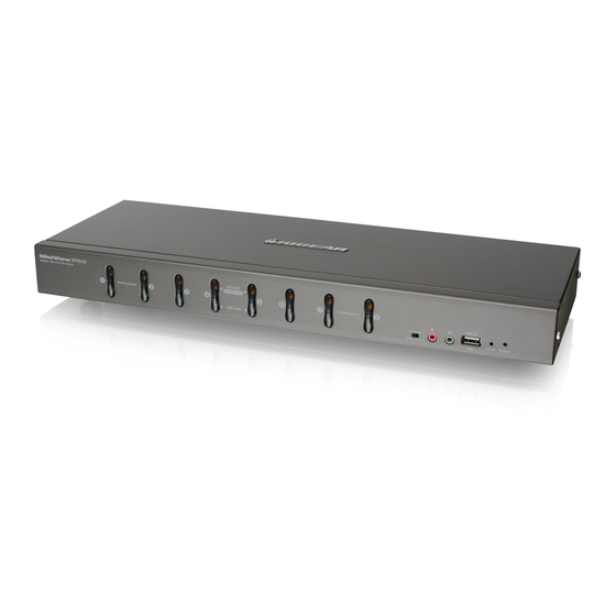
Page 5: Overview
Overview Front view 1. Port 1~8 switch Button 2. Power LED 3. Reset Button 4. USB Sharing Port 5. Firmware Upgrade Recovery Switch 8-Port USB DVI KVM Switch AUTO SCAN K/M RESET Back view 1. Powe Jack 2. CPU 1 - 8 Port 3. -
Page 6: Foot Pad Set Installation
Foot Pad Set Installation Flip the KVM switch upside down. Peel the protective films off of the foot pads, then stick the pads to the four corners, as shown in the diagram below. Rack Mounting Step 1 Remove the screws from the left and right sides of the switch (2 screws total) near the front of the switch. - Page 7 Step 2 Use the M3 x 8 Phillips hex head screws supplied with the rack mounting kit to screw the rack mounting brackets into the sides near the front of the unit. Final Step Place the KVM switch in the rack. Position it so that the holes in the mounting brackets line up with the holes in the rack.
-
Page 8: Console Monitor Connection Options
Console Monitor Connection Options (a) One DVI monitor (DVI-I connector) One DVI monitor (DVI-I) – plug your DVI DVI-I console monitor into the DVI console port located on the unit’s rear panel; (b) One DVI monitor (DVI-D + VGA connectors) One DVI (DVI-D + VGA) monitor –... -
Page 9: Single Level Installation
Single Level Installation 1. Plug your USB keyboard and USB mouse into the USB console ports located on the unit’s rear panel. 2. Depending on your console monitor’s interface, connect your monitor using one of the following methods (see Console Monitor Connection Options, page 8), and power a. - Page 10 4. Plug your secondary microphone and speakers into the console audio ports located on the unit’s rear panel. 5. Using the custom USB DVI KVM cable set provided with this package, plug the DVI connector into any available DVI socket in the KVM port section of the switch, then plug the accompanying USB and audio connectors into their corresponding USB, microphone, and speaker sockets.
-
Page 11: 2-Level Installation (Cascading)
2-Level Installation (Cascading) To control even more computers, additional GCS1108 units can be cascaded from the KVM ports of the First Stage unit. The cascaded GCS1108s that connect back to the First Stage unit are considered Second Stage units. As many as 64 computers can be controlled in a complete two stage installation. -
Page 12: 3-Level Installation (Cascading)
3-Level Installation (Cascading) The procedures for setting up a three stage installation are essentially the same as for a two stage installation. With a three stage setup, as many as 512 computers can be controlled in a complete installation. Note: Switches cannot be cascaded beyond the third level. Once you have finished cabling up (see Two Stage Installation, page 11 if necessary), power up according to the following sequence: 1. -
Page 13: Led Indication
LED Indication Description No LED No computer is connected to the specific port or the computer is connected to the specific port but it is not powered on Orange The specific port has a computer connected and it is powered on, but does not focus on the KVM Green The specific port has focus on the KVM Port Switching Port Switching via Front Panel Switch Button Simply press the specific push button to switch the focus to the specific port Port Switching via On-Screen DIsplay (OSD) Please refer to OSD Operation section. Port Switching via Hotkey Please refer to Hotkey Setting Mode (HSM) section. -
Page 14: On-Screen Display (Osd) Operation
On-screen Display (OSD) Operation Trigger OSD Simply press [Scroll Lock] [Scroll Lock] rapidly. Note: This hotkey sequence can be changed to [Ctrl] [Ctrl] for Mac users. Please refer to Hotkey Setting Mode (HSM) section. OSD Login OSD Login By default, the Login and Password are blanks, so simply press [Enter] [Enter] to login. - Page 15 OSD Main Screen Headings Heading Description This column lists the port ID numbers for all the KVM ports on the installation. The simplest method to access a particular computer is move the highlight bar to it then press Enter. QV If a port is selected for quick view scanning an arrowhead shows in this column.
- Page 16 F1: GOTO F1: GOTO This function is to let you switch to a specific port via port ID or port’s name. Enter [1] to choose from Port Name and [2] to choose from Port Number in the yellow box locating in the bottom of the pink bar. If [1] was chosen, then type in the port’s If [2] was chosen then you can go to a name that you want to go to and then press specific port by entering the port ID. You [Enter]. You can also move the red highlight...
- Page 17 F2: LIST F2: LIST This function allows you to choose a way that you wish to list the ports in the OSD display on the main screen. Simply move the red highlight bar to the option that you wish to choose and press [Enter]. You will see the hand symbol will be pointing at the option that you chose, then simply press [Esc] to exit the function.
- Page 18 F3: SET F3: SET OSD Hotkey There are 10 different settings within the This function allows you to switch the way SET section, which they are as follow: to trigger the hotkey between [Scroll Lock] [Scroll Lock] and [Ctrl] [Ctrl]. Simply move the OSD Hotkey red highlight bar to the hotkey setting that Port ID Display Position...
- Page 19 Scan Duration Port ID Display Mode This function allows you to set the autoscan This function allow you to choose the way time interval between 0 second to 255 you want to show the ports in the OSD seconds (5 second is set by default). Simply main screen –...
- Page 20 Screen Blanker Hotkey Command Mode This function allows you to set the time This function allows you to enable or interval to have the KVM goes to a black disable the hotkey commands. Simply screen. Simply enter the number between 0 press Y for yes and N for no. Then, press to 30 and press [Enter];...
- Page 21 F4: ADM F4: ADM This function will only be shown if you have login as Administrator. There are 11 different functions within the ADM section, which they are as follow: Set User Login Set Accessible Ports Set Logout Timeout Edit Port Names Restore Default Values Clear The Name List Activate Beeper...
- Page 22 Once the user name and password are set correctly, you will see the message in the bottom of the screen indicating the setup is ok. Then simply press [Esc] to exit from the function. Set Accessible Ports This function allows you to setup the access on each port for each user. Use [Spacebar] to cycle through all the entries and press [Enter] to complete the setup.
- Page 23 Set Logout Timeout This function allows you to set a time that the KVM will automatically logout after being idle for a certain period of time. Move the red highlight bar to this function and press [Enter]. Then enter a number from 0-180 (in terms of minutes) as the time interval and press [Enter]. Edit Port Names This function allows you to customize a Enter the port name that you wish to show...
- Page 24 Clear The Name List Restore Default Values This function allows you to clear up all the This function allows you to restore all port names to blanks. Move the red highlight settings into factory default settings. Move bar to Clear The Name List and press the red highlight bar to Restore Default [Enter]. Then type Y to proceed clearing or N Values and press [Enter]. Then type Y to...
-
Page 25: Firmware Upgrade
Set Operating System This function allows you to define what kind of operating system is being used in each port. Simply move the red highlight bar to the desire port and press [Spacebar] to cycle through the options between WIN, MAC, SUN or OTHER. Note: The keyboard Operating platform will change accordingly depending what you have chosen in this function. - Page 26 Keyboard Language This function allows you to choose the keyboard language of your console keyboard. Auto is chosen by default; if you want to change the language, simply move the red highlight bar to the desire keyboard language that you wish to change to and then press [Enter]. Set Computer Video Input Sets the video signal for each KVM port for the computers attached to the GCS1108.
- Page 27 Set Console Video Output Sets the console video output. If the computer attached to the GCS1108 is VGA output, this can be set to display on either the VGA or the DVI console monitor. Options are: DVI-A to VGA – select this option if you have one DVI monitor with a DVI-D plus VGA connector, or if you have two monitors (1 x DVI, 1...
- Page 28 F5: SKP F5: SKP This function allows you to trigger Skip Mode. Simply press [F5] to activate skip mode. When you see a left and right arrow next to the port number as the image below, you can press the arrow keys to skip to different ports.
- Page 29 F6: BRC F6: BRC This function will only be shown if you have logged in as Administrator. Simply press [F6] to trigger Broadcast (BRC) Mode, then you will see a speaker symbol next to the port number. When BRC is activated, your command that you send from the console will be sent to all available computers –...
- Page 30 F8: LOUT F8: LOUT This function allows you to logout of the OSD. So, when another person is trying to access this from the console, he would have to login again. Simply Press Y to proceed the logout and N to cancel.
-
Page 31: Hotkey Setting Mode (Hsm)
Hotkey Setting Mode (HSM) Function Description 1. Press and hold [Num Lock] Invoking hotkey setting mode 2. Press and release [-] 3. Release [Num Lock] Note: To exit HSM manually, press Esc or spacebar. Invoke HSM, then press [h] Change the HSM invocation keys from [Num Lock] to [Ctrl] and from [-] to [F12] Invoke HSM, then press [t] Switch port switching hotkey sequence between... -
Page 32: Mac Keyboard Emulation
Mac Keyboard Emulation The PC compatible (101/104 key) keyboard can emulate the functions of the Mac keyboard. The emulation mappings are listed in the table below. PC Keyboard Mac Keyboard [Alt] [Shift] Shift [Print Screen] [Crtl] Ctrl [Scroll Lock] [Ctrl] [1] [Enter] Return... -
Page 33: Factory Default Settings
Connect the provided firmware upgrade cable to the firmware upgrade port of the KVM and the serial port of your computer. Connect power adapter to your power outlet and the KVM. Step 2 Go to www.iogear.com to download the latest available firmware or the specific firmware that you wish to upgrade to. Step 3 Please make sure all the computers that are connected to the KVM are completely shutdown. - Page 34 Step 5 Read the License Agreement and click “I Agree” then click “Next” if you wish to continue with the firmware upgrade. Otherwise, click “Cancel” to exit. Step 6 Choose the correct KVM* that you wish to perform firmware upgrade from the “Device List” and then click “Next” to continue. Then the Firmware Upgrade Utility will verify if there is a KVM connected to the computer by the firmware upgrade cable. (Check Firmware Version checkbox is optional) Step 7...
- Page 35 Step 8 When the firmware upgrade is done, you will see “Firmware upgrade OK” in the “Status Messages” window. Then simply click “Finish” to complete the whole firmware upgrade process. Final Step Now the KVM will reset by itself and it will be ready for usage after the rest.
-
Page 36: Upgrade Fail
Upgrade Fail If you don’t see “Firmware upgrade OK” in the “Status Messages” window, it means the utility has failed to complete the firmware successfully. If that occurs, please do the following: Step 1 Unplug the power from the KVM. Then, connect the provided firmware upgrade cable to the firmware upgrade port of the KVM and the serial port of your computer. Step 2 Slide the Firmware Upgrade Recovery Switch to the Recover position (slide to the right). Then, connect power adapter back to the KVM. Step 3 Repeat the firmware upgrade process. (Please refer to Firmware Upgrade section) Step 4... -
Page 37: Restore Factory Default Settings
Restore Factory Default Settings This restore will change all settings back to default. This will also have administrator and all user accounts removed from the KVM. All port names and setting will also be removed. In other words, everything will be changed as if it is a brand new unit. Step 1 Unplug the DC connector from the... -
Page 38: Federal Communications Commission (Fcc) Statement
Federal Communications Commission (FCC) Statement This equipment has been tested and found to comply with the limits for a Class A digital device, pursuant to Part 15 of the FCC Rules. These limits are designed to provide reasonable protection against harmful interference in a residential setting. This product generates, uses, and can radiate radio frequency energy and, if not installed and used as directed, it may cause harmful interference to radio communications. -
Page 39: Limited Warranty
Warranty Information This product carries a 3 Year Limited Warranty. For the terms and conditions of this warranty, please go to http://www.iogear.com/support/warranty Register online at http://www.iogear.com/register Important Product Information Product Model Serial Number Contact IOGEAR Toll Free 866-9-IOGEAR (USA) Phone: 949-453-8782 19641 Da Vinci, Foothill Ranch, CA92610 www.iogear.com support@iogear.com... - Page 40 About Us About Us IOGEAR offers connectivity solutions that are innovative, fun, and stylish, helping people enjoy daily life using our high technology products. GREEN IOGEAR is an environmentally conscious company that empha- sizes the importance of conserving natural resources. The use of our technology solutions helps reduce electronic waste.
Need help?
Do you have a question about the 8-Port DVI KVMP Switch and is the answer not in the manual?
Questions and answers