Table of Contents
Advertisement
Advertisement
Table of Contents

Subscribe to Our Youtube Channel
Related Manuals for IOGear MiniView GCS1742


Summary of Contents for IOGear MiniView GCS1742
- Page 1 MiniView ™ Dual View USB KVMP Switch User Manual (GCS1742 / GCS1744) ®...
- Page 3 Microsoft Corporation. IBM is a registered trademark of International Business Machines, Inc. Macintosh, G3/G4 and iMac are registered trademarks of Apple Computer, Inc. All other brand and product names are trademarks or registered trademarks of their respective holders. IOGEAR makes no warranty of any kind with regards to the information presented in this document.
-
Page 4: Table Of Contents
Table of Contents Package Contents Overview Features System Requirements Introduction Installation Basic Operation Hotkey Operation Firmware Upgrade Utility Appendix Specification Technical Support Radio & TV Interference Statement Limited Warranty... -
Page 5: Package Contents
1 x Quick Start Guide 1 x Warranty/Registration Card NOTE: The Power Adapter for the GCS1742/GCS1744 is optional, as the unit obtains its power from the USB port on your computers. If you would like to purchase the power adapter for the unit, please visit www.iogear.com. -
Page 6: Overview
USB keyboard, USB mouse, and two VGA, SVGA, or Multisync monitors. In addition, the GCS1742/1744 incorporates a two port USB hub that allows each of the computers to share any USB peripherals connected to the hub on a one-computer-at a time basis. Recognizing the importance of sound, the switches are also audio enabled. -
Page 7: Features
• Keyboard and mouse emulation for error free booting • Superior video quality - 2048 x 1536; DDC2B • Hot pluggable - add or remove computers for maintenance without powering down the switch • Upgradeable firmware • Supports Windows 98SE or higher, Mac OS 8.6 or higher, SUN Blade 2000/100, (Sun Solaris 8 or... -
Page 8: System Requirements
System Requirements Console Two VGA monitors USB style mouse USB style keyboard Computer Two available VGA ports Type A USB port Audio Only two-piece, powered speakers system supported... -
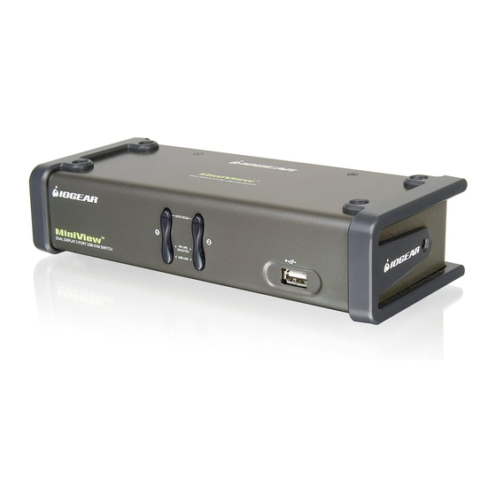
Page 9: Front View
Front View 1. Port selection buttons • Press a switch to access the computer attached to its corresponding port. • Press buttons 1 and 2 simultaneously for 2 seconds to start Auto Scan Mode . 1, 2 2. Port LEDs The Port LEDs are built into the Port Selection Switches. - Page 10 Introduction KVM: • Lights DIM ORANGE to indicate that the computer attached to the corresponding port is up and running (On Line). • Changes to BRIGHT ORANGE to indicate that the computer attached to its corresponding port is the one that has the KVM focus (Selected). •...
-
Page 11: Back View
If you choose to use external power, the power adapter cable plugs into this jack. Note: Use of a power adapter (DC 5V) is optional, and requires a separate purchase. Refer to IOGEAR Part#: 0AD8-0005-261 2. Firmware Upgrade Port The Firmware Upgrade Cable that transfers the firmware upgrade data from the administrator’s... - Page 12 (keyboard, mouse, and peripherals) and the video data for monitor A. *Only cables specifically designed to work with this switch can be used. DO NOT attempt to use ordinary 15-pin VGA connector cables to link these ports to the computers.
-
Page 13: Before You Begin
1. Make sure that power to all the devices you will be connecting up have been turned off. You must unplug the power cords of any computers that have the Keyboard Power On function. Otherwise, the switch will receive power from the computer. 2. Make sure that all devices on the installation are properly grounded. - Page 14 4. Connect your USB peripherals to the USB ports located on the front and rear panels. 5. If you choose to use external power, plug the power adapter cable into the switch’s Power Jack, then plug the power adapter into an AC power source.
- Page 15 Installation (Connection for USB Computers)
-
Page 16: Basic Operation
4. After the switch is up, Power On the computers. NOTE: If the KVM switch has become unresponsive or shows erratic behavior, it is highly suggested that you unplug all cables from the KVM (all KVM cables and power cable) and leave the unit disconnected for 30 minutes. After this, plug all the KVM cables back and... - Page 17 Operation Port ID Numbering Each CPU port on the GCS1742/GCS1744 switch is assigned a port number (1 or 2 for GCS1742; 1 to 4 for GCS1744). The port numbers are marked on the rear panel of the switch. The Port ID of a computer is derived from the CPU port number it is connected to. For example, a computer connected to CPU port 2 has a Port ID of 2.
- Page 18 The USB and Audio focus does not change; they stay on the port that they’re already on. 2. Press and hold a port selection switch for more than 2 seconds to bring the KVM, USB, and Audio focus to the computer attached to its corresponding port 3.
-
Page 19: Hotkey Operation
Hotkey Operation Hotkey Operation The GCS1742/GCS1744 provides an extensive, easy-to-use, hotkey function that makes it convenient to control and configure your KVM installation from the keyboard. NOTE: The table below assumes the use of a PC-compatible keyboard with the Scroll Lock key. If you are using a MAC keyboard (or a keyboard that does not have Scroll Lock key), refer to the section in the manual “Alternate Port Switching Keys”... -
Page 20: Port Switching
Hotkey Operation Port Switching All port switching functions begin by quickly tapping [Scroll Lock] [Scroll Lock] [Enter] the Scroll Lock key twice: [Scroll Lock], [Scroll Lock], [Scroll Lock] [Scroll Lock] [K] [Enter] followed by any of the keys indicated on the table [Scroll Lock] [Scroll Lock] [U] [Enter] below. -
Page 21: Osd Operation
You must exit Auto Scan mode to regain normal console control. • Although the video focus switches from port to port, the keyboard, mouse, and USB focus doesn’t switch. Action Starts Auto Scan. The KVM focus cycles from port to port at 5 second intervals. -
Page 22: Hotkey Setting Mode
Hotkey Operation Hotkey Setting Mode Invoking Hotkey Mode For all Hotkey operations, you must use the number keypad on the right side of your keyboard. To Invoke Hotkey Mode (PC-Compatible keyboard): 1. Press and hold Num Lock key for two seconds 2. - Page 23 Hotkey Operation To invoke Hotkey Mode (Mac keyboards): 1. Press and hold Clear key for two seconds 2. Press and hold Minus key [ - ] for one second 3. Release Minus key [ - ] and within one second also release Clear key Clear Minus The KVM will now enter Hotkey mode;...
- Page 24 Hotkey Operation Note: • If using the Num Lock and Minus key to invoke Hotkey function is not optimal for your setup, refer to the next page to change the hotkey invocation keys. When Hotkey Mode is active, the Caps Lock and Scroll Lock LEDs flash in succession to indicate that HSM is in effect.
- Page 25 In case the default Hotkey Mode invocation keys (Num Lock and Minus) are not optimal in your setup, you may change them to Ctrl and F12, respectively. To switch to an alternate Hotkey Mode invocation, do the following: 1. Invoke Hotkey Mode (see page 22 for PC keyboard and page 23 for Mac keyboard) 2.
- Page 26 Hotkey Operation Alternate Port Switching Keys The port switching activation keys can be changed from tapping Scroll Lock key twice ([Scroll Lock] [Scroll Lock]) to tapping Ctrl key twice ([Ctrl] [Ctrl]). If you have a Mac keyboard (or your keyboard does not have Scroll Lock), you can change the port switching activation keys by doing the following: 1.
- Page 27 Keyboard Operating Platform The GCS1742/GCS1744 default port configuration is for a PC Compatible keyboard operating platform. If you have a Mac attached to a port, you can change a port’s keyboard operating platform configuration as follows: 1. Bring the KVM focus to the desired port 2.
- Page 28 Hotkey Operation List Hotkey Settings To see a list of the current hotkey settings, do the following: 1. Invoke Hotkey Mode (see page 22-23) 2. Open a text editor (such as Notepad or Word) 3. Press F4 on your keyboard to ‘paste’ this information USB Reset If the USB loses focus and needs to be reset, do the following: 1.
- Page 29 Note: The front panel LEDs will flash to indicate that the KVM is in firmware upgrade mode. To exit firmware upgrade mode, you must power off the switch. Restore Default Settings To reset the GCS1742/GCS1744 to its factory default settings, do the following: 1. Invoke Hotkey Mode 2. Press [R] [Enter]...
- Page 30 Operation Sun Keyboard Emulation...
- Page 31 Operation Sun Keyboard Emulation...
- Page 32 Operation MAC Keyboard Emulation...
-
Page 33: Firmware Upgrade Utility
To prepare for the firmware upgrade, do the following: From a computer that is not part of your KVM installation, go to the IOGEAR support site and select the product part number (GCS1742 or GCS1744) to get a list of available Firmware Upgrade Packages. -
Page 34: The Firmware Upgrade Utility
Make sure the power is plugged into the KVM. Once the power is plugged in and the switch is set to upgrade, all of the amber lights on the KVM will flash once per second. Now you are ready to run... -
Page 35: Starting The Upgrade
Starting the Upgrade To upgrade your firmware: Run the downloaded Firmware Upgrade Package file - either by double-clicking the file icon, or by opening a command line and entering the full path to it. The Firmware Upgrade Utility Welcome screen appears: Read and Agree to the License Agreement (enable the I Agree radio button). - Page 36 The Firmware Upgrade Utility 3. Click Next to continue. The Firmware Upgrade Utility main screen appears: The Utility inspects your installation. All the devices capable of being upgraded by the package are listed in the Device List panel.
- Page 37 The Firmware Upgrade Utility 4. As you select a device in the list, its descrip- tion appears in the Device Description panel.
- Page 38 The Firmware Upgrade Utility After you have made your device selection(s), Click Next to perform the upgrade. If you enabled Check Firmware Version , the Utility compares the device’s firmware level with that of the upgrade files. If it finds that the device’s version is higher than the upgrade version, it brings up a dialog box informing you of the situation and gives you the option to...
- Page 39 The Firmware Upgrade Utility As the Upgrade proceeds status messages appear in the Status Messages panel, and the progress toward completion is shown on the Progress bar. After the upgrade has completed, a screen appears to inform you that the procedure was successful: Click Finish to close the Firmware Upgrade Utility.
-
Page 40: Fireware Upgrade
• When the I/O firmware upgrade fails. To perform a firmware upgrade recovery, do the following: Slide the Firmware Upgrade Recovery Switch (see p. 8 drawing) to the Recover position. Power off and restart the switch. Slide the Firmware Upgrade Recovery Switch back to the Normal position. -
Page 41: Appendix
Appendix Troubleshooting... -
Page 42: Specification
Specification... - Page 43 Specification...
-
Page 44: Technical Support
Technical Support If you need technical support, please check out our IOGEAR Tech Info Library (T.I.L.) at www.iogear.com/support for the latest tips, tricks, and troubleshooting. The IOGEAR T.I.L. was designed to provide you with the latest technical information about our products. Most of the answers to your questions can be found here, so please try it out before contacting technical support. -
Page 45: Radio & Tv Interference Statement
Radio & TV Interference Statement WARNING!!! This equipment generates, uses and can radiate radio frequency energy and, if not installed and used in accordance with the instruction manual, may cause interference to radio communications. This equipment has been tested and found to comply with the limits for a Class B computing device pursuant to Subpart J of Part 15 of FCC Rules, which are designed to provide reasonable protection against such interference when operated in a commercial environment. -
Page 46: Limited Warranty
Limited Warranty IN NO EVENT SHALL THE DIRECT VENDOR’S LIABILITY FOR DIRECT, INDIRECT, SPECIAL, INCIDENTAL OR CONSEQUENTIAL DAMAGES RESULTING FROM THE USE OF THE PRODUCT, DISK, OR ITS DOCUMENTATION EXCEED THE PRICE PAID FOR THE PRODUCT. The direct vendor makes no warranty or representation, expressed, implied, or statutory with respect to the contents or use of this documentation, and especially disclaims its quality, performance, merchant- ability, or fitness for any particular purpose. -
Page 47: Contact Info
Contact info. - Page 48 ® 23 Hubble • Irvine, CA 92618 • (P) 949.453.8782 • (F) 949.453.8785 • www.iogear.com...
Need help?
Do you have a question about the MiniView GCS1742 and is the answer not in the manual?
Questions and answers