
Subscribe to Our Youtube Channel
Related Manuals for Merach MR-532


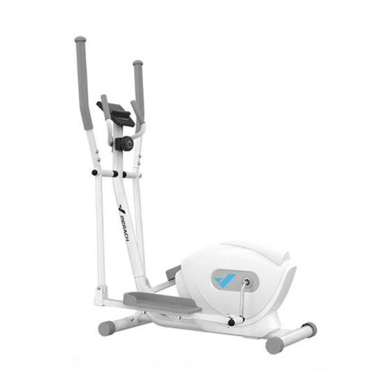
Summary of Contents for Merach MR-532
- Page 1 User ’ s Guide 用户说明书 MR-532 椭圆机 全 国 热 线 : 400-189-1969 官 方 网 站 : w w w . merach.com 公 司 名 称 : 麦瑞克(杭州)健康科技有限公司...
- Page 2 130公斤...
- Page 3 爆炸图A 第2页...
- Page 4 爆炸图B 第3页...
- Page 5 零件清单 索引号 数量 说明 索引号 数量 说明 主架 M3 x 7mm 自攻螺丝 立柱管 M4 x 20mm 钻尾螺丝 前脚管 M4 x 20mm 自攻螺丝 后脚管 M6 x 100mm 外六角螺丝 控制台 M8 x 60mm 内六角螺丝 把手 M8 x 16mm 外六角螺丝 感应下段线 M6 六角螺母 感应棒固定座...
- Page 6 零件识别图A 温馨提示:对照下图找出组装所需的小零件。每幅图下方括弧中的数字是该零件在“零件清单” 中的索引号。索引号后面的数字表示组装所需该零件的数量。(注意:如果零件不在零件包中, 请检查其是否已经预先组装。) M8 弹性垫片 M8 防松螺母 M8 盖形螺母 M8 平垫片 M10 防松螺母 (90)‒16 (84)‒10 (82)‒4 (66)‒8 (83)‒4 M8 弧形垫片 M13 平垫 M10 平垫 中轴垫片 (65)‒18 Φ13 波形垫片 (67)‒2 (69)‒2 (58)‒2 (72)‒4 M5 x 12mm M4 x 16mm M8 x 16mm M10 x 45mm 外六角螺丝...
- Page 7 零件识别图B 温馨提示:对照下图找出组装所需的小零件。每幅图下方括弧中的数字是该零件在“零件清单” 中的索引号。索引号后面的数字表示组装所需该零件的数量。(注意:如果零件不在零件包中, 请检查其是否已经预先组装。) M12 x 110mm 脚踏芯轴(左牙) (78)‒1 M12防松螺母(左牙) (86)‒1 M12 x 110mm 脚踏芯轴(右牙) (70)‒1 M12 防松螺母(右牙) (85)‒1 M8 x 55mm 内六角螺丝 Φ19 波形垫片 (91)‒2 (57)‒2 内六角扳手(L6) 内六角扳手(L8) 第6页...
- Page 8 安装说明 用两个M8*65mm马车螺丝(73)、两个M8弧形垫片 (65)以及两个M8盖形螺母(82)把后脚管(4) 连接至主架(1);待两个马车螺栓全部装入后再 拧紧盖形螺母。 用两个M8*65mm马车螺丝(73)、两个M8弧形垫片 (65)以及两个M8盖形螺母(82)把前脚管(3) 连接至主架(1);待两个马车螺栓全部装入后再 拧紧盖形螺母。 第7页...
- Page 9 安装说明 先将感应上段线(49)与感应下段线(7)相连。 接着,按照下列步骤连接微调上段线(20)与微 调下段线(21)。 参见图 A:将微调线(21)上的金属托架 (A)向上拉,然后将微调线(20)的端部插入 该金属托架内的线束夹。 参见图B:用力向上微调线(20)并将其滑入 金属托架(A)的顶部。 参见图C:用钳子将金属托架(A)上端的叉齿捏 到一起。 最后将线束和电缆多余的部分塞入主架(1)内。 第8页...
- Page 10 安装说明 将立柱管(2)插到主架(1)上。 参见右图A:用两个M8*65mm 内六角螺丝(75)、 四个M8弧形垫片(65)、两个M8弹性垫片(90) 、两个M8防松螺母(84)连接到立柱管(2); 先安装所有螺丝,但不要完全拧紧。 参见右图B:用两个M8*65mm 内六角螺丝(75)、 四个M8弧形垫片(65)、两个M8弹性垫片(90) 、两个M8防松螺母(84)完成连接立柱(2); 先安装防松螺母,然后拧紧。 注意: 不要夹到线束! 第9页...
- Page 11 安装说明 用两颗M4*16mm(95)法兰面螺丝, 将水壶支架(41)固定在立柱管(2)上。 提示:下摇摆管(10/11)、脚踏管(14/15)以 及脚踏芯轴连接U组(88/89)已经预先组装好了。 Grease 润滑油 先将立柱管上中轴两边抹上润滑油。 安装右下摇摆组(11&15&88):依次将定位轴套 (46)、大波垫(57)套入中轴,然后将下摇摆管 套入,用一个平垫(67)、一个M8弹垫(90)、 一个M8*20外六角螺丝固定。 最后装上螺母盖(39)。 用同样方法安装左下摇摆组(10&14&89)。 第10页...
- Page 12 安装说明 安装右踏管芯轴连接U组(88)到右边曲柄上: 先将M12x110mm脚踏芯轴(右牙)光杆表面抹上润滑油,然后将小波垫(58) 套进脚踏芯轴。 将它们一起插进套管(88),用内六角扳手(L8)将芯轴按顺时针拧紧曲柄。 拧进后,另一头用一个平垫(69)、一个防松螺母(85)将其并紧。 注:右边和左边脚踏芯轴头部分别有“L”和“R”字印。 用同样方法安装左踏管芯轴连接U组(89)到左边曲柄上。 润滑油 安装左右上摇摆管: 将右上摇摆管(13)插到右下摇摆管(11)上,用2个弧形垫片 (65)、2个弹性垫片(90)、2个M8x16mm内六角螺丝固定。 用同样方法安装左上摇摆管(12)。 第11页...
- Page 13 安装说明 将右/R脚踏板(33)安装到脚踏管(15)上,用 2个M10x45mm外六角螺丝、2个平垫(72)、2个防 松螺母(83)固定。 用同样方法安装左/L脚踏板(32)。 安装把手(6)到立柱管(2)上,用2个M8弧形 垫片(65)2个M8弹性垫片(90)、2个M8x16mm 内六角螺丝固定。 先将控制台(5)上的感应线接头(C)与感应上段线 (49)相连。然后将控制台(5)固定在立柱管(2) 铁片上,用2个M5*12螺丝(已经装在控制台背面)固定 。 健身车组装完毕后,请检查确认组装是否正确, 功能是否正常。 使用健身车前,请保证所有零件都已经正确紧固。 第12页...
- Page 14 Calories 该模式显示您在训练中消耗的大 致卡路里数。注意:如果您设置了卡路里消耗目标, 该显示区域会显示您在训练中还需消耗的卡路里数。 Total Distance Pulse 该模式在您握住手柄式心率监测器时, 每分钟跳动次数为单位显示您的心率,当您的心率高于 目标值时,该显示区域会闪烁。 SCAN 确保控制台内安装了电池(未随机附带)。若控制台表 面覆有塑料薄膜,请将其撕下。 MODE TIME Time SCAN 该模式显示已用时间。注意:如果您设 置了时间目标,该显示区域会显示您剩余的训练时间。 Speed Distance 该模式以英里为单位显示您在训练 中骑行的里程。注意:如果您设置了里程目标,该显示 区域会显示您剩余的训练里程。 第13页...
- Page 15 Safety Information Before you undertake any programme of exercise that will increase cardiovascular activity please be sure to consult with your doctor. Frequent strenuous exercise should be approved by your doctor and proper use of your product is essential. Please read this manual carefully before commencing assembly of your product or starting to exercise.
- Page 16 EXPLODED VIEW (A) Page2...
- Page 17 EXPLODED VIEW (B) Page3...
-
Page 18: Part List
PART LIST Key N o. Qty. Des cr iption Key N o. Qty. Des cr iption Frame M3 x 7mm Screw Upright M4 x 20mm Self-tapping Screw Front Stabilizer M4 x 20mm Screw Rear Stabilizer M6 x 100mm Bolt Console M8 x 60mm Bolt Handlebar M8 x 16mm Hex Bolt... - Page 19 PART IDENTIFICATION CHART(A) Use the drawings below to identify the small parts needed for assembly. The number in parentheses below each drawing is the key number of the part, from the PART LIST near the end of this manual. The number following the key number is the quantity needed for assembly.
- Page 20 PART IDENTIFICATION CHART(B) Use the drawings below to identify the small parts needed for assembly. The number in parentheses below each drawing is the key number of the part, from the PART LIST near the end of this manual. The number following the key number is the quantity needed for assembly.
-
Page 21: Assembly Instruction
ASSEMBLY INSTRUCTION Identify the Rear Stabilizer (4), which has Leveling Caps (23). Attach the Rear Stabilizer (4) to the Frame (1) with two M8 x 65mm Carriage Bolts (73), two M8 Curved Washers (65), and two M8 Acorn Nuts (82); start both Carriage Bolts, and then tighten the Acorn Nuts. - Page 22 ASSEMBLY INSTRUCTION While a second person holds the Upright (2) near the Frame (1), connect the Upright Wire (49) to the Reed Switch Wire (7). Next, connect the Resistance Cable (20) to the Lower Resistance Cable (21) in the following way: See drawing A.
- Page 23 ASSEMBLY INSTRUCTION Insert the excess wire and cable into the Frame (1). Tip: Avoid pinching the wires and the cables. Slide the Upright (2) onto the Frame (1). Attach the Upright (2) with two M8 x 65mm Bolts (75), four M8 Curved Washers(65), and two M8 Split Washers (90);...
- Page 24 ASSEMBLY INSTRUCTION Attach the Water Bottle Holder (41) to the Upright (2) with two M4 x 16mm Flange Screws (95); start both Flange Screws, and then tighten them. NOTE: Lower Arm(10/11), Pedal Arm(14/15) and Arm Bracket(88/89) have pre-assembled together already. Grease Grease Using a plastic bag to keep your fingers clean,...
- Page 25 ASSEMBLY INSTRUCTION Identify the Right M12x110mm Bolt(70), and the Right M12 Nut(85). Apply grease to the Right M12x110mm Bolt. Attach the Right Arm Bracket(88) to the right side of the crank with the Right M12x110mm Bolt(70), an M13 Wave Washer(58), an M13 Washer(69), and the Right M12 Nut(85).
- Page 26 ASSEMBLY INSTRUCTION Orient the Right Pedal (33) as shown, and attach it to the Right Pedal Arm (15) with two M10 x 45mm Bolts (76), two M10 Washers (72), and two M10 Locknuts (83); start both Bolts, and then tighten the Locknuts. Attach the Left Pedal (32) to the Left Pedal Arm (14) in the same way.
-
Page 27: How To Use The Console
HOW TO USE THE CONSOLE CONSOLE DIAGRAM FEATURES OF THE CONSOLE The easy-to-use console features seven modes that provide instant exercise feedback during your workouts. Time (TIME) —This mode displays the elapsed time. Note: If you set a time goal , this display will show the time remaining in your workout.
Need help?
Do you have a question about the MR-532 and is the answer not in the manual?
Questions and answers