
Subscribe to Our Youtube Channel
Related Manuals for Merach MR-526


Summary of Contents for Merach MR-526
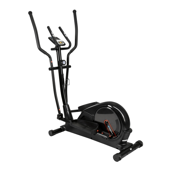
- Page 1 MR-526 ELLIPTICAL TRAINER INSTRUCTION MANUAL Email:service@merach.com Official Website: www.merach.com Company: Zhejiang Yulu Electronic Technology Co., Ltd. Address: 298 Weiye Road, Binjiang District, Hangzhou, Zhejiang Province, China...
- Page 2 MR-526 ELLIPTICAL TRAINER INSTRUCTION MANUAL...
-
Page 3: Table Of Contents
We want to thank you for having chosen an Elliptical trainer and wish you a lot of fun and success during training. Please note and follow the enclosed safety and assembly instructions carefully. If you have questions please do not hesitate to contact us. Support email:service@merach.com. -
Page 4: Safety Instruction
SAFETY INSTRUCTION Before you start training on your home Elliptical trainer, please read the instructions carefully. Be sure to keep the instructions for information, in case of repair and for spare part delivery. This elliptical trainer is made for home use only and tested up to a maximum body weight of 350lb. - Page 5 Ensure that those present are aware of possible hazards, e.g. ■ movable parts during training. Consult your physician before staring with any exercise program. ■ He or she can advise on the kind of training and which impact is suitable. WARNING!INCORRECT/EXCESSIVE TRAINING CAN CAUSE HEALTH INJURIES.
-
Page 6: Exploded Drawing
EXPLODED DRAWING Item.99*2 Item.100*1... -
Page 7: Parts List
MR-526 Components and Parts List Product name Specification Material Quantity JS-10327 outgoing line 120MM, two heartbeat outgoing line Electronic meter 100MM Hand-held heartbeat Flexible rubber sheet Handle weld ∅25 Cup head self-tapping M4*20 screw Semi-round end cover ∅25 Foam ∅25*3T*500mml End cover ∅50*32 upper swing pipe with a small top ring... - Page 8 Nylon powder ∅16.3*022.4 Crank connecting pipe PA+MnS2 Umbrella-head Electrophoresis M8*50A type, tooth length 12MM inner-hexagon screw black Powder metallurgy 11.5*8*15 (pedal tube) M piece welding left 3T, no M5 hole in the middle M piece welding right 3T, no M5 hole in the middle Spring washer 8* office 16*1.5 Plating black...
- Page 9 Disc 8509 black HIPS Housing Left KS-8007 Housing Right KS-8007 Drill screw M5*15 shell 6 Sealing ring ∅60( Hardness 55-60 degrees) Black Ornament cover of front KS-8007 pipe Self-tapping screw M4.5*25 Fine tuning upper The upper section is 540mm and the outgoing line is 30MM section Plating Round head screw...
-
Page 10: Installation Steps
Installation Steps Step 1 STEP 1 After assembling the foot pad (86) and rear foot pipe(87) Fixing the front foot pipe (85) with screws, and aligning hole sites from the lower foot pipe with two carriage screws In the same way, Fixing the rear foot pipe(87) with screws, and aligning hole sites from the lower foot pine with carriage screws(88) Screwing with an Allen wrench (99). - Page 11 Step 3 M piece installation 40 11 STEP 3 Putting the M piece (44R) through the pedal core shaft (75) of the platform (59) parts, and fixing the M piece (44R) on the pedal core shaft (75) with the inner hexagon screw (10), cushions (11) and gasket (40). Screwing with an Allen wrench (99). (Note that the M pieces are divided into left (L) and right (R), which are marked on the package) Step 4 Installation of center shaft and lower swing STEP 4...
- Page 12 Step 5 Installation of upper armrest, pedal tube and M piece STEP 5 Placing the upper armrest (9R) into the position corresponding to the lower swing (25R), and fastening the other side with screws (15) and spring washer(14) as in the previous step. (Refer to the following figure for installation) Putting the rear end of the pedal tube (34R) into the U-shaped opening of the M piece (44R), and then successively penetrating into the corresponding hole position with the inner hexagon screws (42), after that, screwing into inner hexagon screw pumps with the gasket (45) and the nylon cap (46).
- Page 13 Step 6 Installation of pedal plate 35 37 38 39 STEP 6 Putting the pedal plate(36R) into the pedal tube (34R) and aligning its hole, then inserting into the hole corresponding of the pedal plate(36R) and the pedal tube (34R) in turn with the screw pump (35), then installing the plum blossom knob (39), spring washer (38) and spring washer (37) on the screw pump(35) and tightening them up.
- Page 14 Step 8: Installation of kettle holder/fixed handle/electronic meter STEP 8 Firstly, removing the screws (29) from the handlebar stand pipe(30), aligning the hole and fixing the kettle holder (28) on the handlebar stand pipe with the screws (29) according to the figure. Fixing the fixed handle (3) on the handlebar stand pipe(30) with screws (10) and spring washers (14), tightening it with an Allen wrench (99).
- Page 15 Now, your machine is ready to use. Note: Make sure all the screws are tightened before using...
-
Page 16: Operation Instruction Of Multifunctional Sports Monitor
Operation instruction of multifunctional sports monitor VER.01 NO.00044 1. Instrument Function Buttons MODE Status Key ---Selecting the display window to be set or reset; RECOVERY/UP ---In the setting state, setting up the countdown interval, distance, calorie value and temperature (°C or °F) on the corresponding flashing window. ---Pressing this button to enter/exit the heart rate recovery function test when there is heart rate signal input in the stopped movement and non-set state. - Page 17 (1) Measuring the accumulated heat consumption of exercise Measuring the heat (i.e., calories) consumed from the start to the stop of exercise, with the measuring range of 0.0~99.9~999 kcal, it will automatically turn to integer display after counting 99.9 kcal. (2) Calorie alarm function Firstly, setting the calories consumed by exercise, after the exercise starts, the time counts down to zero, then alarming for 10 seconds.
- Page 18 Tips: As signal interference sometimes occurs when the palm catches the metal sheet, the heart rate value displayed in the first 2-3 seconds may be inaccurate and on the high side, which is a normal phenomenon, and then the heart rate will return to normal measurement.
Need help?
Do you have a question about the MR-526 and is the answer not in the manual?
Questions and answers