Table of Contents
Advertisement
Quick Links
The information contained herein is based on sources that we believe to be reliable, but is not guaranteed by us,
may be incomplete or may change without notice
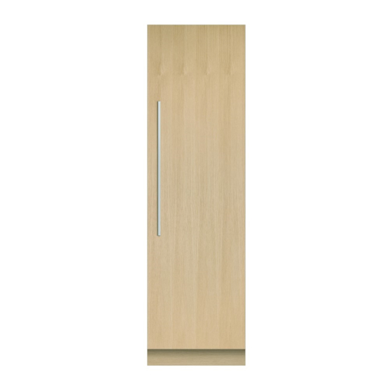
24'' integrated refrigeration column- panel ready (Stainless interior)
Selected Model
Model number
Dimensions
Overall Width (in.)
Depth (in.)
Overall Height (in.)
Exterior Appearence
Built-in
Seemeless Cabinetery Installation
Freestanding
Frontage Color
Features
Configuration
Performance
Temperature Management System
Door swing
Interior Lighting
Sabbath Mode
Door opening angle
SmartTouch™ Control Panel
Temperature zone
Capacity
Total Capacity
Interior Appearance
Interior
ActiveSmart™
Compressor Type
Defrost Type
Door Alarm
Air Fan Management
Electrical Requirements
Volts; Hertz; Amps
Required units and accessories
Joiner kit (grey)
Accessories (Included)
Single Bottle Holders
Accessories (optionnal)
Contemporary Round Stainless Steel
Handle
Contemporary Series Square Stainless
Steel Handle
PRO Round Stainless Steel Handle
PRO Series Square Stainless Steel Handle AHV2-RD84
Accessories (required)
EZKleen™ Stainless steel door panel
Warranty
Full 2 years
5 years warranty
RS2484SRK1
RS2484SRK1
23 3/4''
24''
84''
Yes
Integrated into kitchen cabinetry
Yes
Custom Panels
Single-door integrated column refrigerator
3 cooling mode
ActiveSmart™
Right
LED, top and sides
Yes
90° to 115°
Interior, central
2 independent refrigeration zones
12.4 cu.ft
Stainless Steel
Variable
Automatic
Yes
Variable speed
115V; 60Hz; 10 Amp
AJ-RS84LR
4
AHS-RD84
AHD3-RD84
AHC-RD84
RD2484R4D
Entire Appliance; In-Home; Parts & Labour
Sealed system (parts only)
Advertisement
Table of Contents

Subscribe to Our Youtube Channel
Related Manuals for Fisher & Paykel RS2484SRK1


Summary of Contents for Fisher & Paykel RS2484SRK1
- Page 1 RS2484SRK1 24'' integrated refrigeration column- panel ready (Stainless interior) Selected Model Model number RS2484SRK1 Dimensions Overall Width (in.) 23 3/4'' Depth (in.) 24'' Overall Height (in.) 84'' Exterior Appearence Built-in Seemeless Cabinetery Installation Integrated into kitchen cabinetry Freestanding Frontage Color...
- Page 10 INTEGRATED COLUMNS RS1884FJ, RS2484FJ, RS3084FJ, RS2484S & RS3084S models INSTALLATION GUIDE US CA 847985C 05.18...
-
Page 12: Table Of Contents
TABLE OF CONTENTS SAFETY AND WARNINGS INTEGRATED COLUMNS COMPONENTS LIST PRODUCT DIMENSIONS AND SPECIFICATIONS CABINETRY OPTIONS CAVITY DIMENSIONS DOOR AND TOE KICK PANEL DIMENSIONS CUSTOM DOOR PANEL DIMENSIONS DOOR OPENING ROTATION ELECTRICAL AND PLUMBING BEFORE INSTALLATION UNPACKING AND MOVING YOUR PRODUCT ATTACH THE ANTI-TIP BRACKET CONNECT TO WATER AND POWER SUPPLY SINGLE INSTALLATION... -
Page 13: Safety And Warnings
SAFETY AND WARNINGS INTEGRATED COLUMNS 18” (457mm) 24” (610mm) 30” (762mm) WARNING! Electric Shock Hazard Read and follow the safety and warnings outlined in this installation guide before operating this appliance. Failure to do so can result in death, electric shock, fire or injury to persons. - Page 14 COMPONENTS LIST Installation kit — included with the appliance Door panel attachment kit (848191) Side bracket Bracket slider Side spacer bracket M4 Hex key For SS door panels: For Custom door panels: (6x) (6x) (6x) (1x) 8Gx16 Mush washer screw M5x12 Cross-head screw (30x) (30x) Anti-tip bracket assembly...
-
Page 15: Components List
COMPONENTS LIST MI (miscellaneous items) pack — included with the appliance. Toe kick installation kit — Fisher & Paykel (Stainless steel) toe kick is not included with the appliance. INTEGRATED COLUMNS RS1884FJ RS2484FJ, RS3084FJ, INTEGRATED COLUMNS RS2484S & RS3084S models COLONNES ENCASTRABLES RS1884FJ, RS2484FJ, RS3084FJ, RS2484S &... - Page 16 COMPONENTS LIST Door panels Dual install joiner kit (CA: 24985) — included with the appliance (Freezer model only). Attached to back of appliance. Used for any of the dual install options shown below. Left/Right Left/Left Right/Right Fisher & Paykel (Stainless steel) Customers can supply their door panel is not included own Custom door panel to WALL...
- Page 17 COMPONENTS LIST Hinge change kit — not included with the appliance and must be purchased separately. MODEL LEFT HINGE TO RIGHT HINGE RIGHT HINGE TO LEFT HINGE RS18 848186 848185 RS24 848188 848187 RS30 848190 848189 Each kit includes: Hinge change assembly (1x), Top (fixed) grille assembly (1x) Hinge change assembly Hinge top pocket K05 Top adapter bracket...
-
Page 18: Product Dimensions And Specifications
PRODUCT DIMENSIONS AND SPECIFICATIONS FRONT VIEW PROFILE VIEW RS18 RS24 RS30 PRODUCT DIMENSIONS inches (mm) inches (mm) inches (mm) Overall height of product 84” (2134) 84” (2134) 84” (2134) Overall width of product 17 3/4” (451) 23 3/4” (603) 29 3/4” (756) Overall depth of product 24”... -
Page 19: Cabinetry Options
CABINETRY OPTIONS FRAMELESS CABINETRY FRAMED CABINETRY (Frameless: Aligns the product/s with the cabinetry) (Framed: Aligns the product/s with the frame of the cabinetry) Frameless Framed Note: Images shown for single install. These options are also applicable for dual install. -
Page 20: Cavity Dimensions
CAVITY DIMENSIONS Note: These dimensions are intended for ‘Flush Installation’ only. Flush with front of cabinetry Frameless: finished return Framed: finished return cavity sides and top cavity sides and top PLAN VIEW SINGLE INSTALL DUAL INSTALL RS18 RS24 RS30 RS18 + RS24 RS18 + RS30 RS24 + RS24 RS24 + RS30... -
Page 21: Door And Toe Kick Panel Dimensions
DOOR AND TOE KICK PANEL DIMENSIONS RS18 RS24 RS30 DOOR PANEL DIMENSIONS (STAINLESS STEEL) inches (mm) inches (mm) inches (mm) Height of door panel 79 7/8" (2029) 79 7/8" (2029) 79 7/8" (2029) Width of door panel 17 3/4” (451) 23 3/4" (603) 29 3/4"... - Page 22 DOOR AND TOE KICK PANEL DIMENSIONS SINGLE INSTALL DUAL INSTALL 2” toe kick height 4” toe kick height 6” toe kick height 2 7/8” – 4” toe kick depth (with extra lower grille attached) measured from the front of the door...
-
Page 23: Custom Door Panel Dimensions
CUSTOM DOOR PANEL DIMENSIONS Custom door panel dimensions 14 7/8” (378mm) 8” (203mm) Dimensions apply for the preparation and installation of Custom door panels. For Dwg and Dxf files of the below panel preparation download the 2” (51mm) folder on http://thekitchentools.fisherpaykel.com IMPORTANT! The thickness of the custom door panel can vary provided that the screws ●... - Page 24 CUSTOM DOOR PANEL DIMENSIONS 11 7/8” (302mm) 8” (203mm) 8 7/8” (225mm) 2” (51mm) 2” (51mm) 7/8” x Ø1/8” 3/4” x Ø1/8” (22mm x Ø2mm) 18mm x Ø2mm Do not place handle holes in marked areas to avoid clashing with panel attachment brackets 2 3/8”...
-
Page 25: Door Opening Rotation
DOOR OPENING ROTATION For 90° door swing a hinge limiting bolt is supplied with your appliance. This pin fits in the boreholes of the top hinge (Z). WARNING! Before opening the doors, ensure that the appliance is stable. ● ● Follow these instructions to avoid risks that can cause serious ●... -
Page 26: Electrical And Plumbing
ELECTRICAL AND PLUMBING WARNING! Electric shock hazard! Assume all parts live. Disconnect supply before servicing Left side of cavity and installation. REAR OF CAVITY Floor Electrical and water connections must be within this space if located behind the appliance and must not protrude from the back wall. Note: We recommend to use an isolating switch that is easily accessible to the user after the appliance is installed. -
Page 27: Before Installation
BEFORE INSTALLATION IMPORTANT! Ensure your appliance is not exposed to any heat generating appliance eg cooktop, oven or dishwasher. ● ● The appliance has front and rear rollers for moving the appliance forward and backward. Do not move the appliance sideways to avoid damaging the rollers or the floor covering/surface. ●... -
Page 28: Unpacking And Moving Your Product
UNPACKING AND MOVING YOUR PRODUCT IMPORTANT! WARNING! Follow these instructions to avoid risks that can cause serious injury or death. Be careful when unpacking to prevent damage to the surface of your appliance. ● ● ● ● Ensure that the appliance is stable to prevent from tipping over when unpacking. Keep doors closed until the appliance has been moved to its installation location. -
Page 29: Attach The Anti-Tip Bracket
ATTACH THE ANTI-TIP BRACKET IMPORTANT! Required components/tools: Anti-tip bracket assembly Ensure the door of the appliance is closed when rolling into the cabinetry. DO NOT attempt to open the door until the ● ● – 1x Anti-tip bracket appliance is fully installed. The anti-tip bracket and fittings supplied must be fitted to the wall of the finished enclosure –... -
Page 30: Connect To Water And Power Supply
CONNECT TO WATER AND POWER SUPPLY WARNING! IMPORTANT! Required components/tools: Water filter installation kit The water connection instructions below are intended only for the professional Old water fittings (hose-sets) should not be reused. ● ● ● ● ● ● – 2x Collet locking clip installer. - Page 31 SINGLE INSTALLATION Required components/tools: 4x Cabinet depth alignment gauges ● ● Cross-head screwdriver ● ● Installing depth alignment gauges Note: The alignment gauges are only temporary and removable after installation. Loosen the screws at the right Attach the alignment gauges and left, top and bottom corners so that the screw head passes of the door (A).
- Page 32 SINGLE INSTALLATION IMPORTANT! Required components/tools: Cross-head screwdriver or power driver (PH2 bit) at minimum torque setting Ensure that the hose is not run over when moving the appliance/s to prevent ● ● ● ● Ruler damage and possible water leaks. ●...
- Page 33 SINGLE INSTALLATION IMPORTANT! IMPORTANT! Ensure the doors are in line with the cabinetry front and the appliance is centered. Make sure to remove the depth alignment brackets before fixing the appliance inside ● ● ● ● All four corners of the appliance must be supported firmly onto the floor to the cabinetry.
- Page 34 DUAL INSTALLATION IMPORTANT! Dual installation includes two appliances installed side by Required components/tools: side. Refer to ‘Cavity dimensions’ section for cabinetry 1x Depth alignment gauge We recommend to place the appliance (Freezer) with water ● ● ● ● overall width for dual install. A joiner kit is required for Cross-head screwdriver (powered drill) connection first into the cabinetry to allow you to check the ●...
- Page 35 DUAL INSTALLATION Required components/tools: 4x Depth alignment gauges ● ● Cross-head screwdriver ● ● Installing depth alignment gauges Note: The alignment gauges are only temporary and removable after installation. Loosen the screws at the right Attach the alignment gauges and left, top and bottom corners so that the screw head passes of the door (A).
- Page 36 DUAL INSTALLATION IMPORTANT! Required components/tools: Ruler Make sure that all feet engage the floor and evenly support the product. Tighten the ● ● 1x Barbed plug adjustment screw with screwdriver (do not use powered driver). ● ● Positioning and aligning the first appliance inside the cabinetry Align the top cap of the first appliance flush with the front of the spacer (C).
- Page 37 DUAL INSTALLATION IMPORTANT! Required components/tools: Cross-head screwdriver or power driver Ensure the doors are in line with the cabinetry front and the appliance is centered. ● ● ● ● 5x 8Gx16 Countersunk screws All four corners of the appliance must be supported firmly onto the floor to eliminate ●...
- Page 38 DUAL INSTALLATION Required components/tools: Ruler ● ● 1x Barbed plug ● ● Positioning and aligning the second appliance inside the cabinetry Align the top cap of the second appliance flush with the central spacer and top cap of first appliance (C). Roll the second appliance into the cabinetry side by side with the first appliance.
- Page 39 DUAL INSTALLATION IMPORTANT! Required components/tools: Cross-head screwdriver or power driver (PH2 bit) at minimum torque setting Ensure the door is in line with the cabinetry front and the appliance is centered. ● ● ● ● All four corners of the appliance must be supported firmly onto the floor to eliminate any ●...
- Page 40 DUAL INSTALLATION Required components/tools: Bottom joiner fastener kit 5x 8Gx16 Countersunk screw ● ● ● ● Top joiner fastener kit – 1x M6x16 Washer screw M4 Hex key ● ● ● ● – 1x M5x20 Cap screw – 2x M6x12x3.2 Plastic washer –...
- Page 41 INSTALL WATER FILTER Required components/tools: 1x Water filter ● ● 1x Water filter removal tool (included with appliance) ● ● Flushing the water filter Remove the water filter packaging. Pull the filter tool gently to dislodge from the front of the appliance (A). Before turning on your automatic ice maker, the water Insert the water filter all the way into the filter casing and press firmly until the filter head is pushed further inside the casing (B).
- Page 42 INSTALL BRACKETS TO DOOR PANEL (STAINLESS STEEL) IMPORTANT! Required components/tools: Door panel attachment kit Drill with 3/32” (2.55mm) bit Ensure to protect the finish of the Fisher & Paykel Stainless Steel door panels. Leave ● ● ● ● ● ● –...
- Page 43 INSTALL BRACKETS TO DOOR PANEL (CUSTOM) IMPORTANT! Required components/tools: Door panel attachment kit Drill with 3/32” (2.55mm) bit Ensure the screw pilot holes do not penetrate the full depth of the panel. ● ● ● ● ● ● – 6x Side panel brackets Powered driver (Cross-head) Do not place the handle holes in marked areas to avoid clashing with panel ●...
- Page 44 INSTALL DOOR PANELS IMPORTANT! IMPORTANT! Required components/tools: 4x M5x25 Hex screws The assembly of Fisher & Paykel (Stainless steel) door We recommended to load the shelves in the ● ● ● ● 1x Drill with 3/32” (2.55mm) bit panels and Custom door panels are outlined below. appliance door with weights to ensure an ●...
- Page 45 INSTALL DOOR PANELS Required components/tools: 1x Cross-head screwdriver ● ● M4 Hex key ● ● 1/2” (13mm) Spanner ● ● Adjust the door panel Fix the locking brackets Note: All door panels have full axis adjustment to ensure they are flush with adjacent walls. Loosen the screw at the bottom of the door, and slide the locking bracket out until it To adjust the height of the door panel relative to the door, use M4 hex key to turn the top touches the panel (D).
- Page 46 INSTALL TOE KICK IMPORTANT! Required components/tools: Two magnets are pre-installed to the bottom corners of the toe kick mounting plate. Each 1x Air toe kick seal ● ● magnet has double-sided tape to be attached to the toe kick. This allows both Stainless 1x Toe kick ●...
- Page 47 INSTALL TOE KICK GRILLE IMPORTANT! Required components/tools: Hex key (supplied) For toe kick heights 4 1/2” – 5” (114 – 127mm), shorten the lower grille by cutting along the ● ● ● ● 1x Fixed (top) grille vertical ribs. ● ● 1x Bottom (movable) grille For 2”...
- Page 48 INSTALL CABINET TRIMS Required components/tools: 1x Alcove side trim assembly ● ● Install the side trims Note: Four (4) dual-lock strips are pre-installed along each side trim. Peel off the liners from the dual-lock strips. (A) Slide the trim behind the lower hinge (C), then the top Slot trim in behind top hinge pocket (E), then press (F) hinge (D).
- Page 49 INSTALL CABINET TRIMS Required components/tools: Required components/tools: 1x Center trim 1x Top trim ● ● ● ● Install the center trims (for dual install only) Install the top trim Note: Four (4) dual-lock strips are pre-installed along the center trim. Slide the top trim into hinge pocket of the cabinet (A), and then engage the dual lock at the non-hinge side (B).
- Page 50 INSTALL FLOW DIVIDER AND DOOR TRIMS IMPORTANT! Required components/tools: 1x Door flow divider Top door panel extrusion The door flow divider is pre-assembled to the door of the appliance. It blocks the air flow ● ● ● ● 1x Flow divider cap 2x Door panel side extrusion from bypassing in front of the bottom grille.
- Page 51 OPTIONAL — CHANGING OVER DOOR HINGES You have the option to change the door hinge side of your appliance from right hand Required components/tools: hinge to left hand hinge or vice versa. A hinge change kit is required for this installation. T20 star screwdriver ●...
- Page 52 OPTIONAL — CHANGING OVER DOOR HINGES Required components/tools: T20 star screwdriver ● ● Flat head screwdriver ● ● Removing the top door hinge Rotate the top hinge (A) outwards and remove the top hinge pocket cover (B) using the flat head screwdriver in the slot of the cover. Remove the hinge by unscrewing the M5x12 pan head screws (2x) (C), and set aside for later use.
- Page 53 OPTIONAL — CHANGING OVER DOOR HINGES Required components/tools: T20 star screwdriver ● ● Flat head screwdriver ● ● Moving the sensor housing (RS18 & RS24 only) Unclip the reed switch from the housing (A). Move the sensor housing so that the opposite reed switch Reinstall the sensor housing using #8x16 screws (2x) Unhook the interceptor board harness from sensor clip is aligned with the center of the cabinet (D).
- Page 54 OPTIONAL — CHANGING OVER DOOR HINGES Required components/tools: Left/right hinge change kit (refer to T20 star screwdriver ● ● ● ● ‘Components list’) Flat head screwdriver ● ● – 1x Top (fixed) grille assembly – Hinge change assembly Top hinge installation Reinstall the hinge top bracket and bracket spacer with M5x12 countersunk screws (A) on the new hinge side at the other side of the appliance.
- Page 55 OPTIONAL — CHANGING OVER DOOR HINGES Required components/tools: 2x K05 Top adapter bracket ● ● 2x K05 Bottom adapter bracket ● ● T20 star screwdriver ● ● Flat head screwdriver ● ● Door brackets Remove the top adapter bracket from the top of the door by unscrewing M5x10 screws (4x) (A).
- Page 56 OPTIONAL — CHANGING OVER DOOR HINGES Required components/tools: T20 Star screwdriver ● ● Flat head screwdriver ● ● Hex driver ● ● Door installation Activate the hinge spring by turning the T20 star screws to the “I” position (B). Reinstall the door to the appliance by fixing M6x10 hex screws (4x) into the hinges (A). Top hinge Bottom hinge Return the appliance to the upright position.
- Page 57 FINAL CHECKLIST TO BE COMPLETED BY THE INSTALLER All models Check all parts are installed. Ensure the appliance is level. Ensure the appliance is securely fastened to the cabinetry with the supplied anti-tip bracket and fittings. Ensure the door/drawer can open and close freely with no resistance from surrounding cabinetry.
- Page 58 DATA SHEET 24" Integrated Column Fridge / Freezer Model nos: RS2484SR1 / RS2484SRK1 / RS2484FRJ1 / RS2484FRJK1 with Stainless Steel Door panel RD2484R4D, Handle AHD3-RD84 and Stainless Steel Toekick Panel AKRS24041 NOTE: Left hand hinge model is a mirrored version of image DATUM : FRONT OF CHASSIS shown.
- Page 59 DATA SHEET 24" Integrated Column Fridge / Freezer Model nos: RS2484SR1 / RS2484SRK1 / RS2484FRJ1 / RS2484FRJK1 with Stainless Steel Door panel RD2484R4D, Handle AHD3-RD84 and Stainless Steel Toekick Panel AKRS24041 NOTE: Left hand hinge model is a mirrored version of image DATUM : FRONT OF CHASSIS shown.
- Page 60 DATA SHEET 23 3/4" 24" Integrated Column Fridge / Freezer Model nos: RS2484SR1 / RS2484SRK1 / RS2484FRJ1 / RS2484FRJK1 NOTE: Left hand hinge model is a mirrored version of image shown. RS2484SL1 / RS2484SLK1 / RS2484FLJ1 / RS2484FLJK1 (refer page 2 for metric measurements)
- Page 61 DATA SHEET 24" Integrated Column Fridge / Freezer Model nos: RS2484SR1 / RS2484SRK1 / RS2484FRJ1 / RS2484FRJK1 NOTE: Left hand hinge model is a mirrored version of image shown. RS2484SL1 / RS2484SLK1 / RS2484FLJ1 / RS2484FLJK1 (refer page 1 for imperial measurements)
- Page 62 DATA SHEET 24" Professional Integrated Column Fridge / Freezer Model nos: RS2484SR1 / RS2484SRK1 / RS2484FRJ1 / RS2484FRJK1 with Stainless Steel Door panel RD2484R4D, Handle AHC-RD84 and Stainless Steel Toekick Panel AKRS24041 NOTE: Left hand hinge model is a mirrored version of image DATUM : FRONT OF CHASSIS shown.
- Page 63 DATA SHEET 24" Professional Integrated Column Fridge / Freezer Model nos: RS2484SR1 / RS2484SRK1 / RS2484FRJ1 / RS2484FRJK1 with Stainless Steel Door panel RD2484R4D, Handle AHC-RD84 and Stainless Steel Toekick Panel AKRS24041 NOTE: Left hand hinge model is a mirrored version of image DATUM : FRONT OF CHASSIS shown.
Need help?
Do you have a question about the RS2484SRK1 and is the answer not in the manual?
Questions and answers