Hussmann Q3-DC Installation And Operation Manual
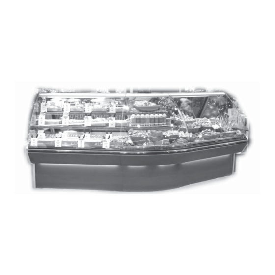
Deli service case
Hide thumbs
Also See for Q3-DC:
- Accessory installation manual (3 pages) ,
- Technical data sheet (14 pages)
Table of Contents
Advertisement
Quick Links
Advertisement
Table of Contents

Subscribe to Our Youtube Channel
Related Manuals for Hussmann Q3-DC


Summary of Contents for Hussmann Q3-DC
- Page 1 Q3-DC Deli Service Case INSTALLATION & OPERATION GUIDE...
-
Page 2: Table Of Contents
HUSSMANN CHINO PRODUCT CONTROL The serial number and shipping date of all equipment has been recorded in Hussmann’s fi les for warranty and replacement part purposes. All correspondence pertaining to warranty or parts ordering must include... -
Page 3: Cut & Plan Views
fi t when cases are joined in the fi eld. When joining, use a carpenters level and adjust legs accordingly. The legs on the Q3-DC are adjustable and do not require shims. Simply screw the leg up or down to adjust height. - Page 4 (apply additional silicone if necessary). Remove tape applied on line #4. 11.Remove front, back and end shipping braces. Q3-DC REFRIGERATED WEDGES AND STANDARD CASES Line up taper pins and line-up plates with holes on adjoining case. Bolting is located at the rear of the case, behind the air discharge wall, and behind the front body panel.
-
Page 5: Plumbing
Unscrew the rear panels with Phillips screwdriver. ELECTRONIC EXPANSION VALVE (OPTIONAL) A wide variety of electronic expansion valves and case controllers can be utilized. Please refer to EEV and controller Hussmann’s information sheet. Sensors for Q3-DC 0907... -
Page 6: Electrical
They are not intended nor suitable for large motors or other external appliances. ALWAYS DISCONNECT ELECRICAL POWER AT MAIN DISCONNECT WHEN SERVICING OR REPLACING ANY ELECTRICAL COMPONENT. This includes (but not limites to) Fans, Heaters, Q3-DC 0907 BEFORE SERVICING Thermostats, and Lights... -
Page 7: Ashrae Color Code
Actual ampere draw may be less than specifi ed. Field wiring from the refrigeration control panel to the merchandisers is required for refrigeration thermostats. Most component amperes are listed in the “Case Specs” section, but always check the serial plate. -
Page 8: User Information
Hussmann cases were not designed to “heat up” or “cool down” product—but rather to maintain an item’s proper temperature for maximum shelf life. -
Page 9: Non-Glare Glass
CLEANING Hussmann recommends using a clean damp chamois, or a paper towel marked as “dust and abrasive free” ® with 210 Plastic Cleaner and Polish available by calling Sumner Labs at 1-800-542-8656. -
Page 10: Maintenance
TOWARD THE MOTOR. COILS The coils used in Hussmann merchandisers may be repaired in the fi eld. Materials are available from local refrigeration wholesalers. Hussmann recommends using #15 Sil-Fos for repairs. -
Page 11: Electrical And Refrigeration Specifi Cations
Q3-DC 0907 Electrical and Refrigeration Specifi cations... -
Page 12: Electrical Schematics
0392457 .29A BUNDLE ~120 VAC - 1Ø - 60 Hz BROWN LABELED FAN CIRCUIT ~120 VAC - 1Ø - 60 Hz. MCA= .54A MOP= 15A 4/10/07 5/4/07 Q3-DC-3R/Q3-DS-3R/Q3-BC-3R/Q3-BS-3R SUCTION SOLENOID (1) 225-01-3202 T-STAT (1) 225-01-0707 SWITCH 125-01-0311 BUNDLE WHITE/BLACK LABELED THERMOSTAT... - Page 13 ~120 VAC - 1Ø - 60 Hz BROWN LABELED FAN CIRCUIT ~120 VAC - 1Ø - 60 Hz. MCA= .54A MOP= 15A 4/10/07 5/4/07 Q3-DC-4R/Q3-DS-4R/Q3-BC-4R/Q3-BS-4R Q3-DC 0907 SUCTION SOLENOID (1) 225-01-3202 T-STAT (1) 225-01-0707 SWITCH 125-01-0311 BUNDLE WHITE/BLACK LABELED THERMOSTAT...
- Page 14 SUCTION SOLENOID (1) 225-01-3202 T-STAT (1) 225-01-0707 SWITCH 125-01-0311 BUNDLE WHITE/BLACK LABELED THERMOSTAT BUNDLE CIRCUIT PURPLE LABELED HEATER CIRCUIT ~120 VAC - 1Ø - 50/60 Hz ~120 VAC - 1Ø - 60 Hz MCA= 2.0A MOP= 15A Q3 REMOTE Q3-DC-5R/Q3-DS-5R/Q3-BC-5R/Q3-BS-5R W1760001-03...
- Page 15 EVAP FAN MOTOR (2)0392457 .29A EA BUNDLE BROWN LABELED FAN CIRCUIT ~120 VAC - 1Ø - 60 Hz. MCA= 1.01A MOP= 15A 4/10/07 5/4/07 Q3-DC 0907 SUCTION SOLENOID (1) 225-01-3202 T-STAT (1) 225-01-0707 SWITCH 125-01-0311 BUNDLE WHITE/BLACK LABELED THERMOSTAT CIRCUIT ~120 VAC - 1Ø...
- Page 16 BROWN ~120 VAC - 1Ø - 50/60 Hz LABELED FAN CIRCUIT ~120 VAC - 1Ø - 60 Hz. MCA= 1.01A MOP= 15A 4/10/07 5/4/07 Q3-DC-7R/Q3-DS-7R/Q3-BC-7R/Q3-BS-7R Q3-DC 0907 SUCTION SOLENOID (1) 225-01-3202 T-STAT (1) 225-01-0707 SWITCH 125-01-0311 BUNDLE WHITE/BLACK LABELED THERMOSTAT...
- Page 17 EVAP FAN MOTOR (2)0392457 .29A EA BUNDLE BROWN LABELED FAN CIRCUIT ~120 VAC - 1Ø - 60 Hz. MCA= 1.01A MOP= 15A 4/10/07 5/4/07 Q3-DC 0907 SUCTION SOLENOID (1) 225-01-3202 T-STAT (1) 225-01-0707 SWITCH 125-01-0311 BUNDLE WHITE/BLACK LABELED THERMOSTAT CIRCUIT ~120 VAC - 1Ø...
- Page 18 EVAP FAN MOTOR (3)0392457 .29A EA BUNDLE BROWN LABELED FAN CIRCUIT ~120 VAC - 1Ø - 60 Hz. MCA= 1.3A MOP= 15A 4/10/07 5/4/07 Q3-DC 0907 SUCTION SOLENOID (1) 225-01-3202 T-STAT (1) 225-01-0707 SWITCH 125-01-0311 BUNDLE WHITE/BLACK BUNDLE LABELED PURPLE...
- Page 19 (2)125-01-2012 .18A EA BUNDLE BROWN LABELED FAN CIRCUIT L1 N 120VAC - 1Ø - 60 Hz. MCA= 1.6A MOP= 15A 4/10/07 5/4/07 Q3-DC 0907 SUCTION SOLENOID (1) 225-01-3202 T-STAT (1) 225-01-0707 SWITCH 125-01-0311 BUNDLE WHITE/BLACK LABELED THERMOSTAT CIRCUIT ~120 VAC - 1Ø - 50/60 Hz ~120 VAC - 1Ø...
- Page 20 LIGHT CIRCUIT=1.93 A LEDGE LIGHTS SHELF LIGHTS (OPTIONAL) (OPTIONAL) L1 N ~120 VAC - 1Ø - 60 Hz. MCA= 1.48A MOP= 15A 4/10/07 5/4/07 Q3-DC 0907 SUCTION SOLENOID (1) 225-01-3202 AIR SWEEP T-STAT FANS COMAIR™ (1) 225-01-0707 MX2B1-E1 (3)125-01-2012 .18A EA...
- Page 21 .18A EA BUNDLE BROWN LABELED FAN CIRCUIT L1 N 120VAC - 1Ø - 60 Hz. MCA= 1.48A MOP= 15A 4/10/07 5/4/07 Q3-DC 0907 SUCTION SOLENOID (1) 225-01-3202 T-STAT (1) 225-01-0707 EVAP FAN MOTOR (3)0392457 .29A EA SWITCH 125-01-0311 BUNDLE WHITE/BLACK...
- Page 22 LOADING LOADING LOADING LOADING LOADING LOADING LOADING LOADING LOADING LOADING LOADING LOADING LOADING LOADING LOADING 120 V 120 V MODEL: Q3-DC-3R/ MODEL: Q3-DC-5R/ Q3-DS-3R/Q3-BC-3R/ Q3-DS-5R/Q3-BC-5R/ Q3-BS-3R Q3-BS-5R WITH OPTIONS WITH OPTIONS LOADING LOADING LOADING LOADING LOADING LOADING LOADING LOADING LOADING...
-
Page 23: Appendices
The installer is responsible for following the instal- lation instructions and recommendations provided Appendices by Hussmann for the installation of each individual type refrigerator. Refrigeration piping should be sized according to Hussmann’s equipment recommendations and installed in accordance with normal refrigeration practices. - Page 24 APPENDIX D. – Recommendations to user - Refrigerated Hussmann should provide instructions and recom- mendations for proper periodic cleaning. The user will be responsible for such cleaning, including the cleaning of low temperature equipment within the compartment and the cooling coil area(s).
-
Page 25: Warranty
Daily cleaning of the external areas surrounding the storage or display compartments with detergent and water will keep the equipment presentable and prevent grime buildup. Load levels as defi ned by Hussmann must be observed. The best preservation is achieved by following these rules: a) Buy quality products. - Page 26 The MODEL NAME and SERIAL NUMBER is required in order to provide you with the correct parts and information for your particular unit. They can be found on a small metal plate on the unit. Please note them below for future reference. Q3-DC 0907...
Need help?
Do you have a question about the Q3-DC and is the answer not in the manual?
Questions and answers