
Subscribe to Our Youtube Channel
Related Manuals for Hussmann Q3


Summary of Contents for Hussmann Q3
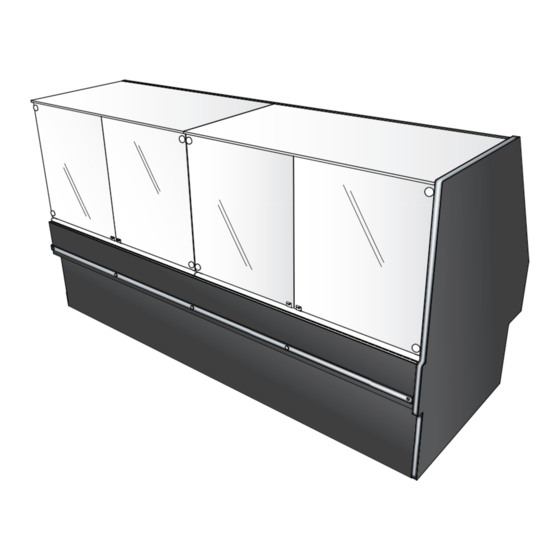
- Page 1 /SPECIALTY 0318 VERTICAL BLOWER MEAT SERVICE MERCHANDISER U S E R M A N U A L - Q3-MV-BC-8 / Straight Vertical Case - Q3-MV-BC-12 / Straight Vertical Case Remote...
-
Page 2: Table Of Contents
Refrigeration Spec Sheets Exterior Surfaces Interior Surfaces Troubleshooting DOE 2012 Hussmann refrigerated merchandisers con gured for sale for use in the United States Energy E ciency meet or surpass the requirements of the DOE 2012 energy e ciency standards. Compliant... -
Page 3: Notice
Notice WARNING 1. DO NOT overload or stand over top of case. Glass breakage may occur if precautions are disregarded. *Broken glass can cause lacerations, cuts, and puncture wounds which may result in severed arteries or tendons, amputations, eye injuries, or exposure to disease. -
Page 4: General Information
Shortages: Check your shipment for any possible shortages of material. If a shortage should exist and is found to be the responsibility of Hussmann Chino, notify Hussmann Chino. If such a shortage involves the carrier, notify the carrier immediately, and request an inspection. Hussmann Chino will acknowledge shortages within ten days from receipt of equipment. -
Page 5: Case Sections
Case Sections Q3-MV-BC Multi-Deck Service Deli Case (673) (305) (587) (356) (629) (1327) (391) (581) (654) (264) (638) (149) (1051) Q3-MV-BC (149) (562) (638) (714) (203) (127) (156) Fogging (1064) Elec System Drain Refrig (264) End Panels customer side (29) -
Page 6: Installation
Case is to arrive at store as was shipped form factory. See reference above for proper shipment referencing. Receiving Case Upon receiving your new Hussmann Case all equipment should be thoroughly examined for shipping damage before and during unloading. This equipment has been carefully inspected at our factory. -
Page 7: Placement
Installation (cont’d) Placement panels. Check for damage before discarding packaging. Important: See lifting instructions to properly lift In the case a fork lift truck is not available follow case when being placed on dollies or permanent the demonstration below to properly lift case us- location. -
Page 8: Q3Mv-Bc Lifting And Transport Instructions
Instructions at one end underneath the deck with a forklift to allow the placement of rollers or dollies. 1. The Q3-MV-BC can be lifted by a forklift at 6. Evenly support the entire base structure on typical lifting points. rollers or dollies before attempting to move. -
Page 9: Front Body Panel Install
Installation (cont’d) Front Body Panel Install Fasten Rear Body Panel Install (1) Align pre drilled holes to base of case A Phillips Screw Driver/Bit will be needed to (2) Secure top and bottom of rear panel using install body panels. fasteners as shown below. -
Page 10: Leveler Adjustment
Installation (cont’d) Leveler Adjustment Note: To avoid removing concrete flooring, begin line up levelling from the Highest point of the Position the case at the highest point. Set a long store floor. magnetized level (4ft [1220 mm] or more) on either underneath the deck or on top of the case. Ensure to level case from front to back and side to side. -
Page 11: Parts List
Parts List (Field installation) 1H97637 1 PER JOINT Joining part 3 3/8"-16 NUT/BOLT 3 PER JOINT LOOSE 3/8"-0. 5 625" OD WASHER 4 PER JOINT LOOSE 1H97784 1 PER JOINT Joininh part 4 1/4"-0.5625" OD WASHER 1 PER JOINT LOOSE / TOP CANOPY ONLY 1H63905 1 PER JOINT Joining part 1... -
Page 12: Q3-Mv-Bc Case Adjustments
Installation (cont’d) - Page 13 Installation (cont’d)
- Page 14 Installation (cont’d)
-
Page 15: Joining Preparation
Installation (cont’d) - Page 16 Installation (cont’d)
- Page 17 Installation (cont’d)
-
Page 18: Refrigeration
In the case pressure was not maintained sealed at factory already. Seal both the inside contact your Hussmann Service Tech for further and outside. We recommend using an expanding assistance. -
Page 19: Refrigeration Spec Sheets
Refrigeration Spec Sheets MEAT SERVICE CASE, VERTICAL GLASS REVISION DATE 03/01/18 HUSSMANN - Q3-MV-BC-R (CHINO) REFRIGERATION DATA: EST. CAPACITY ** GLYCOL (20°F TEMPERATURE (ºF) REFG. (BTU/HR/FT) INLET, 6° RISE) CASE VELOCITY CHRG. CASE LENGTHS CASE USAGE LENGTHS RATING (LBS) (FT/MIN) -
Page 20: Electrical
Electrical Field Wiring Merchandiser Electrical Data Field wiring must be sized for component am- Technical data sheets are shipped with this peres stamped on the serial plate (refer to pg 16 manual. The data sheets provide merchandiser for location). Actual ampere draw may be less electrical data. -
Page 21: Remove Rear Raceway
Electrical Cont’d Remove Rear Raceway Electrical Conduit (Electrical Box) The Merchandisers Electrical access is located The Merchandisers Electrical conduit can be at the rear of the case. Fasteners must be re- found inside the compartment at the rear. Re- moved in order to gain access. See illustration moving the raceway will gain access to the elec- below. -
Page 22: Electrical Wiring Diagram
Electrical Wiring Diagram... - Page 23 Electrical Wiring Diagram (Cont’d)
- Page 24 Electrical Wiring Diagram (Cont’d)
- Page 25 Electrical Wiring Diagram (Cont’d)
- Page 26 Electrical Wiring Diagram (Cont’d)
-
Page 27: Miatech Fogging System
Miatech Fogging System SOP MIATECH FOGGING SYSTEM Q3-MV-BC-R SETUP AND INSTALLATION Be advised, for case lineups consisting of two 8-foot cases (or other compatible combinations), the fogger system may be shared over 2 cases to reduce cost. One case will be designated as the primary case and will house the fogger system. -
Page 28: Fogging System Mounting
1. FOGGER SYSTEM MOUNTING a. Physical location i. Remove the rear skirt for easy access to the tray, GFCIs and case thru hole(s). ii. When ready, connect the fogger power to the GFCI labeled “Fogging System”. This circuit is switched at the case control panel as opposed to the adjacent GFCI which is hot once the case power connections are made. - Page 29 c. The number and location of nozzles: Each fogger nozzle will mist a 3’ or 4’ section of the case. The nozzles will be mounted in the close-offs for the crumb tray under the rear discharge air grills. Case Number of Location Length Heated Nozzles...
-
Page 30: Water And Air Hose Routing
ATER AND AIR HOSE ROUTING a. Trim the black hard plastic tubing (see figure 6, pg 3) surrounding the 3 lines coming out of each heated nozzle, ahead of the case drop (figure 4, pg 2). Do not pass the hard plastic through the case drop. -
Page 31: Case Settings
4. CASE SETTINGS a. Defrost – IMPORTANT! – THE SUPPLIED CASE CONTROLLER WILL CONTROL DEFROST AND IS PROGRAMMED AT THE FACTORY WITH THE SETTINGS BELOW. This case does not need a defrost from the rack. A rack defrost will lead to erratic operation and potential loss of product. -
Page 32: Field Electrical Connections
FIELD ELECTRICAL CONNECTIONS IMPORTANT! - For primary/secondary case lineups; the secondary case does not have controls for the suction solenoid or defrost air heater. Two sets of leads will be bundled in both cases for a field connection when the cases are placed and bolted together. Trim excess wiring and make the indicated electrical connections for the solenoid and return air heater as per below: Figure 10: The dotted lines indicate the secondary solenoid and secondary return air heater. - Page 33 IMPORTANT! - Heater relay connection: The return air heater ships from the factory disabled. If a fogging system is installed, the return air heater must be connected. The lead will be labeled as “Install to terminal 1 if fogging system is installed.” i.
-
Page 34: System Clock
SYSTEM CLOCK: The Fogging system has a clock located behind the rear raceway panel. Figure 15: Grasslin FM1D20-120 Figure 16: The system clock interrupts the fogging system during non- programmable time clock to match store's display hours. The factory settings are listed below. If different, the meat department display times with an store’s actual times should be programmed into the clock. - Page 35 DISCHARGE AIR GRILLS: The discharge grills are positional. The center grills all have the same outlet pattern. The case ends (defined as bordering a case end panel) will have a slightly more open pattern. Ensure that the grills are located in the correct positions: PN 3052446.
- Page 36 PROCEDURE AND CHECKLIST: Hussmann Responsibility □ Make the heater relay connection at terminal 1 (pg 8). □ If applicable, make the appropriate primary to secondary case electrical connections for the return air heater and suction solenoid. See page 6 for details.
-
Page 37: Fogger System Troubleshooting
FOGGER SYSTEM TROUBLESHOOTING Problem Possible Cause Possible Solution Ensure the power switch on Miatech unit turned to "ON". Ensure the "Fogger System" switch on the case is switched to the "ON" position, and the light is illuminated. No Power to Fogging GFCI on power outlet tripped;... -
Page 38: User Information
User Information Start Up Load Limit See the merchandisers Data Sheet Set for refrig- Each Merchandiser has a Load Limit. Shelf life of erant settings and defrost requirements. Bring perishables will shorten if Load Limit is violated. merchandisers down to the operating tempera- AT NO TIME SHOULD THE MERCHANDISER tures listed on the Data Sheet. - Page 39 • Turn and rotate the meat. The blood which gives the pink color works down in time which The Q3-MV-BC service cases are easy to work, causes surface discoloration and dehydra- attractive merchandising display cases capable tion. When turned before this condition oc-...
- Page 40 User Information Cont’d Removing Deck Pans CAUTION Always use caution while removing deck pans from merchandiser. Located below the deck pans is a heating element to assist in the deforst process. Due to the increased moisture from the HEATING ELEMENT Fogging system, frost build up must be defrosted by the heating element creating a HOT SPOT UNDERNEATH DECK...
-
Page 41: Case Cleaning
User Information Cont’d Case Cleaning Cleaning Stainless Steel Surfaces Long life and satisfactory performance of any Use non abrasive cleaning materials, and always equipment are dependent upon the care it re- polish with grain of steel. Use warm water or add ceives. - Page 42 User Information Cont’d Do Not Use: • Abrasive cleaners and scouring pads, as these will mar the finish. • A hose on lighted shelves or submerge shelves in water. • Solvent, oil or acidic based cleaners on any interior surfaces. • A hose on LED Lights or any other electrical component.
-
Page 43: Troubleshooting
Troubleshooting Problem Possible Cause Possible Solution Case temperature is Ambient conditions may Check case position in store. Is the case located near an too warm. be affecting the case open door, window, electric fan or air conditioning vent that operation. may cause air currents? Case must be located minimum 15 Ft away from doors or windows. - Page 44 Troubleshooting Cont’d Problem Possible Cause Possible Solution Water has pooled Case drain is clogged. Clear drain. under case. PVC drains under case Repair as needed. may have a leak. Case tub has unsealed Seal as needed. opening. If the case is in a line- Install case to case joint and seal as needed.
- Page 45 To obtain warranty information or other support, contact your Hussmann representative. Please include the model and serial number of the product. Hussmann Warranty / Technical Assistance (800) 592-2060 Hussmann Corporation, Corporate Headquarters: Bridgeton, Missouri 63044 2014...
Need help?
Do you have a question about the Q3 and is the answer not in the manual?
Questions and answers