Table of Contents
Advertisement
Quick Links
Advertisement
Table of Contents

Subscribe to Our Youtube Channel
Related Manuals for ACS Alcolock WR2


Summary of Contents for ACS Alcolock WR2
- Page 1 WR2 Calibration Station Instruction Manual...
- Page 2 Toronto, Ontario M9W 6J2 CANADA acs-corp.com ALCOLOCK, ALCOSIM, ALCOHOL COUNTERMEASURE SYSTEMS, ACS, INTERTRACK and The Molly are trademarks of Alcohol Countermeasure Systems (International) Inc. and are used under license. Alcohol Countermeasure Systems is the trading style of Alcohol Countermeasure Systems Corp ©...
-
Page 3: Table Of Contents
Contents Introduction ................................1 Glossary of terminology ............................2 ACS part numbers ..............................2 Part descriptions ..............................2 Power supply ..................................2 Auto-Cal ECU ..................................2 ALCOSIM breath alcohol simulator ............................2 Calibration Station (CS) ................................ 3 Aquarium air pump ................................3 ITE software .................................. -
Page 5: Introduction
1.0 Introduction The ACS Calibration Station (CS) is diagnostic equipment designed to establish and maintain compliance of the ALCOLOCK WR2 alcohol interlock Handset (HS). The following are main components required for HS calibration: Calibration Station WR2 Electronic Control Unit (ECU) programmed to Auto-Cal mode ... -
Page 6: Glossary Of Terminology
3.0 ACS part numbers This section list parts supplied by ACS, which are required by the Service Centre for the calibration of the ALCOLOCK WR2 device. Contact ACS to order the following parts (for contact information, refer to acs-corp.com). -
Page 7: Calibration Station (Cs)
The ITE software application downloads the calibration record from the ECU, for analysis. Alcohol reference solution The alcohol reference solution used in the CS is provided by ACS Corp in 500 mL containers. Each container is labelled with: BAC value of the solution ... -
Page 8: Alcosim Breath Alcohol Simulator Diagram
5.0 ALCOSIM breath alcohol simulator diagram... -
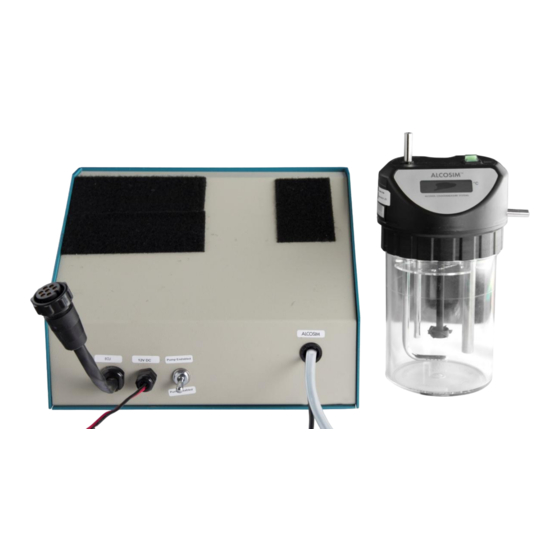
Page 9: Calibration Station (Cs) Diagram
6.0 Calibration Station (CS) diagram Fastening pad (ECU) Fastening pad (HS) Communication plug (to ECU) Power wires Pump switch Communication cable (to ALCOSIM) Air outlet tube – I ALIBRATION TATION NSTRUCTION ANUAL... -
Page 10: Unpacking, Inspection And Operating Check
7.0 Unpacking, inspection and operating check ATTENTION! Note the following before unpacking any components or adding water to the ALCOSIM simulator: Ensure that the ALCOSIM simulator is unplugged and switched off until instructed Ensure that the CS is switched to “pump disabled” and is disconnected from a power source until instructed ... -
Page 11: Inspecting The Aquarium Air Pump
Inspecting the power supply The power supply is an ACS provided part, but a locally purchased unit could be employed. The power supply must provide sufficient current for successful operation of the Auto-Cal station, or it can lead to Handset pump failures. 14amp output is the minimum. - Page 12 Connect the ALCOSIM power input to a wall port. Switch ON the ALCOSIM simulator. ALCOSIM power input: ALCOSIM power switch: The propeller begins turning and the solution automatically begins heating up to 34°C. This takes up to 20 minutes. The ALCOSIM screen displays the temperature.
- Page 13 Connect the CS air outlet tube (front) to the ALCOSIM air inlet (top). Connect the CS communication cable (front) to the ALCOSIM communication cable add-on (79-007851). CS communication cable ALCOSIM communication cable add-on – I ALIBRATION TATION NSTRUCTION ANUAL...
- Page 14 Connect the ALCOSIM communication cable to the ALCOSIM communication port. ATTENTION! Make certain that the pegs align; the plug is brittle. 10. Connect the CS red and black wires (front) to the red and black output terminals of the power supply (Back) and return the binding posts.
- Page 15 12. Connect the ECU power plug to the CS power input cable (front). The ECU automatically powers on. 13. Connect the WR2 Genius+ to the ECU communication port. 14. Press ECU button to Zero tests. 15. The ECU displays Service. 16.
- Page 16 18. Referring to your solution bottle label, use the WR2 Genius+ key pad to enter the bottle number (see example circled below), and press 7(OK). 19. The ECU displays OK. 20. Unplug the Genius WR2+ from the ECU. The test counter on the WR2 ECU is reset 25 tests. 21.
-
Page 17: Functional Test
22. Connect the back of the HS to the right-side HS fastening pad, with the HS sampling port facing forward. 23. Switch the CS to “Pump Enabled” (front). 24. Press the ECU button to Zero tests. NOTE: The test counter on the ECU counts down from 25 tests/5 days ... -
Page 18: Verification Process
Verification process The HS is tested two to three times for compliance in the calibration BAC range and, in particular, the verification BAC range. Press button to commence testing. The ECU will display to following messages during testing: - - - - - While sample being injected WAIT While test sample being analyzed... -
Page 19: Automatic Disabling
10.0 Automatic disabling The CS is pre-programmed to disable any HS that does not pass the calibration parameters. Once disabled, the HS cannot be reactivated. Disabled HSs should be immediately returned to your distributor. 11.0 Resetting the internal counter (changing solution) After 25 tests or 5 days the Change spit trap and solution. -
Page 20: Result
Click on the pull-down menu and select Cal Stat. Read. A Transaction Screen similar to the following will be displayed: At this stage, proceed to the CS and complete the following Genius+ procedure. Connect Genius+ to ECU on CS. Enter with the USER ID for the Genius+ as follows: Select Diagnostic (number 3 on key pad) Select Previous (number 6) - the ECU screen will show Enter ID Select Odometer (Button #) on the genius to enter # plus 3 digits... -
Page 21: Troubleshooting
14.0 Troubleshooting 14.1 ALCOSIM simulator – troubleshooting checklist In the event of a calibration failure, first check that: The plastic tubing is not overused, and it is free of condensation The alcohol reference solution value is 50 mg/dL (0.50 g/L) ... -
Page 22: Problem Statements
16.0 Problem statements ATTENTION! If any of the below problem messages are displayed, you must return the HS to the distributor for servicing. Current Cal Factor Not Valid Cal Factor too Low Cal Factor too High Calibration Out of Range ... - Page 23 IRM-ENG- 60-000337-A © 2012...
Need help?
Do you have a question about the Alcolock WR2 and is the answer not in the manual?
Questions and answers