Advertisement
Quick Links
Advertisement

Subscribe to Our Youtube Channel
Related Manuals for tayco Norris Series


Summary of Contents for tayco Norris Series
- Page 1 Norris installation guide February 2020...
- Page 2 Installation Service toll free I 1.800.675.4092 Mon - Fri I 8:30 am – 5:00 pm EST www.tayco.com...
-
Page 3: Table Of Contents
Table of Contents General Instructions 1|02 Installation Checklist ........................ 1 Care and Maintenance ......................2 Application Guide ........................3 Norris Boardroom Tables 5|14 Norris Boardroom Table – 1 Surface ..................5 Norris Boardroom Table – 2 Surfaces ..................10 Norris Boardroom Table – 3 Surfaces ..................14... -
Page 4: Installation Checklist
Installation Checklist Perform a site inspection prior to the installation date to check existing site conditions and identify constraints and limitations that could possibly cause delays or problems during the actual installation. SITE ACCESSIBILITY 1. Verify existing loading facilities and proximity of loading dock to staging area. 2. -
Page 5: Care And Maintenance
American Corporation. Painted Metals Tayco’s painted metal products are powder-paint-coated. To clean these products, use a damp cloth, using only a small amount of lukewarm water if necessary. Dry with a clean a dry cloth. To avoid scratching and damaging the painted surface, do not use hard bristled brushes or abrasive. -
Page 6: Application Guide
17.25 30.02 TYPICAL TABLE 2 `` THIS DOCUMENT IS THE PROPERTY OF TAYCO PANELINK LTD. AND CONTAINS CONFIDENTIAL AND/OR PROPRIETARY TYPICAL TABLE 4 BE REPRODUCED, DISTRIBUTED, EXAMINED BY THIRD PARTY OR DIVULGED, IN WHOLE OR IN PART, WITHOUT THE WRI... - Page 7 AND CONTAINS CONFIDENTIAL AND/OR PROPRIETARY INFORMATION. THE CONTENTS OF THIS DOCUMENT ARE NOT TO BE REPRODUCED, DISTRIBUTED, EXAMINED BY THIRD PARTY OR DIVULGED, IN WHOLE OR IN PART, WITHOUT THE WRITTEN AUTHORIZATION FROM TAYCO PANELINK LTD. `` TYPICAL TABLE 4 DIMENSIONS ARE IN...
-
Page 8: Norris Boardroom Table - 1 Surface
Norris boardroom table – 1 Surface Note: The procedure below is for Boat, Straight, Super Ellipse and Video boardroom tables. 1. Place the table top face down on a clean solid surface or floor; Position the bridge to table top, (Figure 1). Continued on the next page >>... - Page 9 Norris boardroom table – 1 Surface 2. To install the table base; position and attach the steel gable to bridge, using 3/8-16” X 1 1/2” Hex bolt, (Figure 2). Repeat this procedure to install the other steel gable. Note: The steel gables for Video boardroom tables have two different sizes.
- Page 10 Norris boardroom table – 1 Surface 4. Securely fasten the base, using #10 X 1” Pan Head Screws, (Figure 4). 5. Lift the table into an upright position; level and adjust the glides if necessary. 6. Set the power grommet into the hole of the table top and lay the electrical wires and communication cables in the...
- Page 11 Norris boardroom table – 1 Surface 7. Pull the ‘V’ knuckle strikes from the ‘V’ knuckle catch of the steel gables, (Figure 6). 8. Securely fasten the ‘V’ knuckle strikes to outer gable cover, using #6 X 5/8” Pan Head Screws into the pre-drilled holes, (Figure 7).
- Page 12 Norris boardroom table – 1 Surface 11. Angle the end gable at 30 degrees; Insert the Z brackets into the slots of the steel gable and push the gable cover gently, (Figure 8). Repeat this procedure for each gable cover required. 12.
-
Page 13: Norris Boardroom Table - 2 Surfaces
Norris boardroom table – 2 Surfaces The procedure below is for Boat, Straight, Super Ellipse and Video boardroom tables. 1. Assemble the table base, using 3/8-16” X 1-1/2” Hex Bolt, (Figure 1). 2. Attach bolts from the thru holes on the inside of bridge to the threaded holes on the plinth. - Page 14 Norris boardroom table – 2 Surfaces 4. Place the 2 surfaces on top of table base and attach them together by inserting wooden dowels, (Figure 2). 5. Place the top bolt into the groove. Tighten the bolt using a box wrench, (Figure 3). 6.
- Page 15 Norris boardroom table – 2 Surfaces 7. Position the table base using the pre-drilled positioning holes and attach it to table top using #10 X 1” Oval Head Screws, (Figure 4). 8. Securely fasten the table base, using #10 X 1” Pan Head Screws, (Figure 5).
- Page 16 Norris boardroom table – 2 Surfaces 9. Set the power grommets into the hole of the table top and lay the electrical wires and communication cables in the bridge and end gables, (Figure 6). 10. Please refer to pages 8-9. Follow Steps 7 to 12 to install the gable and bridge covers.
-
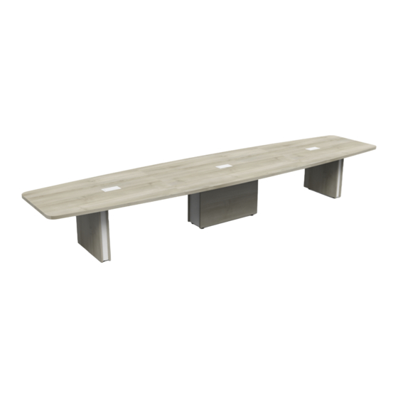
Page 17: Norris Boardroom Table - 3 Surfaces
Norris boardroom table – 3 Surfaces Note: The procedure below is for Boat, Straight, and Super Ellipse boardroom tables. 1. Please refer to page 10. Follow Steps 1 - 3 to install the table base. 2. Place the three surfaces on top of table base and attach them together by inserting wooden dowels, (Figure 1). - Page 20 0220...
Need help?
Do you have a question about the Norris Series and is the answer not in the manual?
Questions and answers