Advertisement
Quick Links
ZKJ-TF2Z005EN-B
ORIGINAL INSTRUCTIONS
Instruction Manual
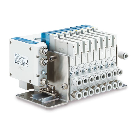
Vacuum Manifold for fieldbus system
Series ZKJ
The intended use of the vacuum manifold is to generate vacuum and
control the operation of suction and release.
1 Safety Instructions
These safety instructions are intended to prevent hazardous situations
and/or equipment damage. These instructions indicate the level of
potential hazard with the labels of "Caution," "Warning" or "Danger."
They are all important notes for safety and must be followed in addition
*1)
to International Standards (ISO/IEC)
, and other safety regulations.
*1)
ISO 4414: Pneumatic fluid power - General rules relating to systems.
ISO 4413: Hydraulic fluid power - General rules relating to systems.
IEC 60204-1: Safety of machinery - Electrical equipment of machines.
(Part 1: General requirements)
ISO 10218-1: Robots and robotic devices - Safety requirements for
industrial robots - Part 1: Robots.
• Refer to product catalogue, Operation Manual and Handling
Precautions for SMC Products for additional information.
• Keep this manual in a safe place for future reference.
Caution indicates a hazard with a low level of risk which, if
Caution
not avoided, could result in minor or moderate injury.
Warning indicates a hazard with a medium level of risk
Warning
which, if not avoided, could result in death or serious injury.
Danger indicates a hazard with a high level of risk which, if
Danger
not avoided, will result in death or serious injury.
Warning
• Always ensure compliance with relevant safety laws and
standards.
• All work must be carried out in a safe manner by a qualified person in
compliance with applicable national regulations.
2 Specifications
Note 1)
2.1 Ejector specifications
Model
ZKJ07
ZKJ10
ZKJ12
Fluid
Air
Nozzle diameter [mm]
0.7
1.0
1.2
Standard supply pressure [MPa]
0.4
Max. vacuum pressure
Note 2)
-89
[kPa]
Without
exhaust
31
53
63
Port
sealing valve
exhaust
With exhaust
30
48
57
sealing valve
Without
High-noise
exhaust
31
51
60
sealing valve
reduction
silencer
Without
exhaust
exhaust
30
45
54
sealing valve
Note 2)
Air consumption
26
48
68
[L/min(ANR)]
2 Specifications - continued
Ejector specifications - continued
Supply pressure range [MPa]
Supply valve: N.C., Release
Type of actuation
Supply valve: N.O., Release
Note 4)
Response time at 0.5 [MPa]
Max. operating frequency [Hz]
Manual override
Power consumption [W]
o
Ambient temperature range [
C]
0 to 50 (No condensation)
Note 5)
2
Vibration resistance
[m/s
]
Impact resistance
Note 6)
[m/s
2
]
500 [VAC] for 1 [min] between
Withstand voltage
FE and all accessible terminals
10 [MΩ] or more (500 [VDC] is
Insulation resistance
Note 7)
Enclosure
Table 1.
Note 1) The supply valve and release valve mounted on this product is the SMC
dual 3-port valve JSY3000 series. Refer to the Web Catalogue for details
on the JSY3000 series.
Note 2) Values are at the standard supply pressure and based on SMC's
measurement standards.
Note 3) If the vacuum port diameter is Φ6 or Φ1/4'', Max. Suction flow rate is
reduced by 15% or less.
Note 4) It shows supply valve/release valve specification. Based on dynamic
performance test, JIS B 8419-2010 (Coil temperature: 20[
voltage).
Note 5) The characteristics are satisfied when tested for 2 hours in each of the X,
Y and Z directions at 10 to 500 Hz without energization (Initial value).
Note 6) The characteristics are satisfied when tested one time in each of the X, Y
and Z directions without energization (Initial value).
Note 7) Cannot be used in an environment where oil, such as cutting oil, splashes
or it is constantly exposed to water. Take appropriate protective measures.
Note 8, 9)
2.2 Noise Level (Reference value)
Model
ZKJ07
Noise level [dB(A)]
52
Table 2.
Note 8) Values at the standard supply pressure.
Note 9) Values are with 1 ejector generating vacuum pressure adequately for
adsorption with high-noise reduction silencer (Not guaranteed values).
2.3 SI Unit specifications
ZKJ15
1.5
Series
Protocol
74
Table 3
For details, refer to SI unit operation manual for 'Specifications'.
-
Note 10)
2.4 Pressure sensor specifications
68
Rated
Without exhaust sealing valve
pressure
With exhaust sealing valve
range [kPa]
-
Proof pressure [kPa]
Accuracy
Current consumption (per piece)
102
Table 4.
Note 10) Cannot be used for actuating the cylinders. Do not apply release pressure
constantly.
2 Specifications - continued
0.3 to 0.5
Special products (-X) might have specifications different from those
valve: N.C. (ZKJ-JSY3A)
shown in this section. Contact SMC for specific drawings.
valve: N.C. (ZKJ-JSY3E)
3 Installation
23 [ms] or less
3.1 Installation
3
Non-locking push type
3.1.1 Mounting
0.4
Mount and tighten the manifold using the holes in the end plate (4xM6)
30
150
given between FE and all
accessible terminals)
IP65
3.1.2 Connecting cables
Refer to SI unit operation manual for 'Wiring'. Select the appropriate
cables to make with the connectors mounted on the SI unit.
o
C], at rated
3.1.3 Ground terminal
The SI unit must be connected to FE (Functional Earth) to divert
electromagnetic interference. For maximum protection, the FE cable
should be as thick and short as reasonably possible.
• Do not install the product unless the safety instructions have been read
and understood.
3.2 Environment
ZKJ10
ZKJ12
ZKJ15
63
67
71
• Do not use in an environment where corrosive gases, chemicals, salt
water or steam are present.
• Do not use in an explosive atmosphere.
• Do not expose to direct sunlight. Use a suitable protective cover.
• Do not install in a location subject to vibration or impact in excess of
the product's specifications.
• Do not mount in a location exposed to radiant heat that would result in
temperatures in excess of the product's specifications.
3.3 Piping
• Before connecting piping make sure to clean up chips, cutting oil, dust
etc.
• When installing piping or fittings, ensure sealant material does not
enter inside the port. When using seal tape, leave 1 thread exposed
on the end of the pipe/fitting.
• Tighten fittings to the specified tightening torque.
EX260
3.4 Lubrication
PROFINET, IO-Link
• SMC products have been lubricated for life at manufacture, and do not
require lubrication in service.
• If a lubricant is used in the system, refer to catalogue for details.
-100 to 100
4 Settings
-100 to 200
500
Refer to SI unit operation manual. The setting file can be found on the
± 3%F.S.
SMC website.
15 [mA] or less
5 How to Order
Refer to catalogue for 'How to Order'.
6 Outline Dimensions
Refer to catalogue for outline dimensions.
Warning
7 Maintenance
7.1 General maintenance
• Not following proper maintenance procedures could cause the product
to malfunction and lead to equipment damage.
• If handled improperly, compressed air can be dangerous.
• Maintenance of pneumatic systems should be performed only by
qualified personnel.
• Before performing maintenance, turn off the power supply and be sure
to cut off the supply pressure. Confirm that the air is released to
atmosphere.
• After installation and maintenance, apply operating pressure and
power to the equipment and perform appropriate functional and
leakage tests to make sure the equipment is installed correctly.
• If any electrical connections are disturbed during maintenance, ensure
they are reconnected correctly and safety checks are carried out as
required to ensure continued compliance with applicable national
regulations.
• Do not make any modification to the product.
• Do not disassemble the product, unless required by installation or
maintenance instructions.
Implement the maintenance and checks shown below in order to use
the ejector safely and in an appropriate way for a long period of time:
• Maintenance should be performed according to the procedure
indicated in the Operation Manual. Improper handling can cause
damage and malfunction of equipment and machinery.
• Maintenance work
Compressed air can be dangerous when handled incorrectly.
Therefore, in addition to observing the product specifications,
replacement of elements and other maintenance activities should be
performed by personnel with sufficient knowledge and experience
Warning
pertaining to pneumatic equipment.
• Draining
Remove condensate from air filters and mist separators regularly. If
the collected drainage is drained to the downstream side, it can stick
inside of the product, causing operation failure and failure to reach the
specified vacuum pressure.
• Replace the filter element built into the ejector and the silencer
Warning
regularly.
It is recommended to replace the filter element and the silencer when
the pressure drop reaches 5kPa as a guideline. The replacement
cycle varies depending on the operating conditions, operating
environment and supply air quality.
However, if there is a vacuum pressure drop and/or delay in the
vacuum (adsorption) response time which causes problem with the
settings during operation, stop the operation of the product and
replace the element regardless of the above mentioned replacement
guideline.
• Operation in an environment where there is a lot of dust in the air
The processing capacity of the filter element built into the product may
Caution
be insufficient. It is recommended to use SMC's air suction filter (ZFA,
ZFB, ZFC series) in order to avoid problems beforehand.
• Check before and after the maintenance work
When the product is to be removed, turn off the power supply, and be
sure to cut off the supply pressure and exhaust the compressed air.
Confirm that the air is released to atmosphere.
When mounting the product after the maintenance work, supply
compressed air, connect to the power, check if it functions properly
and have a leakage inspection.
• Do not disassemble or modify the product, other than the replacement
Caution
of parts specified in the operation manual.
• Tighten to the specified tightening torque.
If the tightening torque is exceeded, the product, the mounting screws
and brackets can be broken. Insufficient torque can cause
displacement of the product from each proper position and loosening
of the mounting screws.
• Before piping, perform air blow (flushing) or cleaning to remove any
cutting chips, cutting oil, dust, etc. from the piping. Otherwise, failure
or malfunction may occur.
• If the fluid contains foreign matter, install and connect a filter or mist
separator to the inlet. Otherwise, failure, malfunction or inaccurate
measurements from the pressure sensor may occur.
Caution
Page 1 of 2
Advertisement

Subscribe to Our Youtube Channel
Related Manuals for SMC Networks ZKJ Series


Summary of Contents for SMC Networks ZKJ Series
- Page 1 ZKJ-TF2Z005EN-B 2 Specifications - continued 2 Specifications - continued 6 Outline Dimensions ORIGINAL INSTRUCTIONS Ejector specifications - continued Refer to catalogue for outline dimensions. Supply pressure range [MPa] 0.3 to 0.5 Warning 7 Maintenance Supply valve: N.C., Release Special products (-X) might have specifications different from those Instruction Manual valve: N.C.
- Page 2 ZKJ-TF2Z005EN-B 8 Limitations of Use 8.1 Limited warranty and disclaimer/compliance requirements Refer to Handling Precautions for SMC Products. Caution Exhaust Noise When vacuum ejector generates vacuum, noise can be heard from the exhaust port when the standard supply pressure is close to the pressure that generates peak vacuum pressure making vacuum pressure unstable.
Need help?
Do you have a question about the ZKJ Series and is the answer not in the manual?
Questions and answers