
Subscribe to Our Youtube Channel
Related Manuals for SMC Networks ZKJ Series

Summary of Contents for SMC Networks ZKJ Series
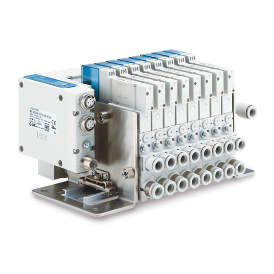
- Page 1 No. ZKJ-OM00201 PRODUCT NAME Vacuum Manifold for fieldbus system MODEL / Series / Product Number ZKJ Series...
-
Page 2: Table Of Contents
Contents Safety Instructions 1. How to Order 2. Summary of Product Parts 3. Installation 3.1. Installation 3.2. Air Supply 3.3. Piping 4. Solenoid Valve 5. SI Unit 6. Construction/Replacement Parts 6.1. Construction 6.2. Component Parts 6.3. Replacement Parts 7. Exploded View of Manifold/Replacement Parts 7.1. -
Page 3: Safety Instructions
Safety Instructions These safety instructions are intended to prevent hazardous situations and/or equipment damage. These instructions indicate the level of potential hazard with the labels of “Caution,” “Warning” or “Danger.” They are all important notes for safety and must be followed in addition to International Standards (ISO/IEC) , and other safety regulations. - Page 4 Safety Instructions Caution 1. The product is provided for use in manufacturing industries. The product herein described is basically provided for peaceful use in manufacturing industries. If considering using the product in other industries, consult SMC beforehand and exchange specifications or a contract if necessary.
- Page 5 ■Safety Instructions Warning Do not disassemble, modify (including the replacement of board) or repair other than instructed in this manual. Otherwise, an injury or failure can result. Disassembly prohibited Do not operate the product outside of the specifications. Do not use for flammable or harmful fluids. Fire, malfunction, or damage to the product can result.
- Page 6 Caution Do not touch the terminals and connectors while the power is on. Otherwise electric shock, malfunction or damage to the switch can result. Do not touch Perform sufficient trial run. Otherwise, injury or damage to the system can result due to suction failure depending on the conditions of the suction of the workpiece or the pressure switch settings.
- Page 7 - Do not use the product to drive an actuator such as a cylinder (when release pressure is constantly applied). Otherwise this can result in damage or reduced performance. - Not suitable for use as an emergency shutoff valve, etc. The valves listed in this catalog are not designed for safety applications such as an emergency shutoff valve.
- Page 8 Operating environment - IP65 enclosure: The protection structure against solid foreign objects is dust-tight type and the protection structure against water-jet-proof type. Dust-tight means that no dust can enter the inside of the equipment. Water-jet-proof means that the product is not adversely affected by direct water jets from any direction. That is, even when direct water jets are applied to the product for 3 minutes by means of the pre-determined method, there is no water entry that hinders the correct operation inside the equipment.
- Page 9 Adjustment and Operation - If using the product to detect very small pressures, warm up the product for 10 to 15 minutes first. There will be a drift on the display of approximately 1% for 10 minutes after the power supply is turned on. - Perform settings suitable for the operating conditions.
-
Page 10: How To Order
1. How to Order ■Manifold ZZKJ 04 - FAN - L8 (1) Number of Manifold Stations Note 1) 2) 3) Symbol Manifold Stations Vacuum ejector stations 4 stations Max. 4 stations 8 stations Max. 8 stations 12 stations Max. 12 stations 16 stations Max. - Page 11 (3) Exhaust (EXH) port Symbol Exhaust type High-noise reduction silencer exhaust Port exhaust Note 5) Note 5) Port size of exhaust port; mm: ø8, inch: ø5/16” (4) Combination of Supply Valve and Release Valve Symbol Supply valve Release valve N.C. N.C.
-
Page 12: Summary Of Product Parts
2. Summary of Product Parts ■Vacuum Ejector Supply valve manual override Release valve manual override Manual override for residual pressure release (Option) Pressure sensor Air pressure supply (P) port (Selected by model number) Vacuum release flow adjusting needle Vacuum (V) port Exhaust (EXH) port (Selected by model number) ■Manifold... -
Page 13: Installation
3. Installation 3.1. Installation Mount and tighten the manifold using the holes in the end plate (4 x M6). 4 x M6 Mounting hole ■Precaution Do not drop, hit, or apply excessive impact to the product when handling it. Even if the body looks undamaged, the internal components may be damaged, leading to a malfunction. Load to the vacuum manifold The vacuum manifold is made of resin;... -
Page 14: Piping
3. Quality of supply air It is recommended to use compressed air which purity class is 2:6:3 of ISO8573-1:2010. Supply air containing foreign matter, water, oil or condensate, etc. can cause malfunction of supply and release valve. It is recommended that an air filter and a mist separator are connected to the upstream side of the ejector and the pump system to prevent foreign matter (drainage) from entering into the product, and perform periodic maintenance of the mist separator to keep supply air quality. - Page 15 ■Precautions 1. When piping to the product, be careful not to confuse a vacuum port with an exhaust port. Otherwise this can result in damage or reduced performance. Apply compressed air after confirming that the piping is connected correctly. 2. For maintenance and inspection purposes, ensure to install the residual pressure release system when piping.
-
Page 16: Solenoid Valve
4. Solenoid Valve Manual override operation ■ Regardless of an electric signal for the valve, the manual override is used for switching the main valve. Connected actuator is started by manual operation. An alarm may occur when using the manual override during PROFINET communication. -
Page 17: Unit
5. SI Unit The SI Unit controls a vacuum manifold. The SI Unit compatible with the vacuum manifold is shown below. Part number Protocol EX260-VPN1 PROFINET The following vacuum manifold parameters can be set by SI Unit. Parameter Explanation Channel Set whether or not to mount the ejector. - Page 18 Pressure value ■ The pressure value parameter for energy saving function (P2, H2), vacuum confirmation (P1, H1) and release confirmation (P3, H3) can be set. The release pressure varies depending on the supply pressure, piping conditions and the number of ejectors operating simultaneously. Set the release confirmation signal value with care.
-
Page 19: Construction/Replacement Parts
6. Construction/Replacement Parts 6.1. Construction Manual override for residual pressure release (Option) (10) Ejector supply (P) Port Port exhaust (11) 6.2. Component Parts Item Material Remarks FKM, HNBR, SUS and aluminum are also used Valve adapter assembly FKM and SUS are also used Valve body assembly FKM, HNBR, SUS and aluminum are also used Sealing valve body assembly... -
Page 20: Replacement Parts
6.3. Replacement Parts (5) Supply valve and release valve assembly [With two mounting screws] (Tightening torque for mounting screw: 0.2 Nm) ZKJ - JSY3 A 00 - 5U Valve type Symbol Supply valve Release valve N.C. N.C. N.O. N.C. (7) Vacuum port adapter assembly (Purchasing order is available in units of 10 pieces.) ZKJ - VA1S 8 F - A One-touch fitting size... -
Page 21: Exploded View Of Manifold/Replacement Parts
7. Exploded View of Manifold/Replacement Parts 7.1. Exploded View of Manifold U side Tightening torque: 0.6 Nm D side 7.2. Component Parts for Manifold Item Material Remarks SI Unit Refer to Replacement Parts on Page 21 Control Unit Refer to Replacement Parts on Page 21 End plate D... -
Page 22: Replacement Parts
7.3. Replacement Parts (1) SI Unit (6) Protection plate EX260 - V PN 1 ZKJ - PL2 - 4 - A SI Unit Applicable stations Symbol Protocol For 4 stations manifold PROFINET For 8 stations manifold For 12 stations manifold For 16 stations manifold (2) Control Unit (7) Tension bolt (3 pcs. -
Page 23: Manifold Option
7.4. Manifold Option ■Blanking plate (With two connector plug assembly) ZKJ - BP1 - A Used in situations where ejectors are not mounted for manifold. Connector plug assembly (2pcs) ■Plug for individual supply ZK2 - MP2F - A By placing “Plug for individual supply” in a vacuum manifold’s pressure supply passage, two different pressures can be supplied to one manifold. -
Page 24: How To Increase Manifold Stations
7.5. How to Increase Manifold Stations 1) Remove two screws from the back of the Control Unit and two screws from the side of SI Unit. SI Unit Control Unit Tightening torque: 0.6 Nm No need to remove Tightening torque: 0.9 Nm 2) Separate the connected ejectors from the Control Unit. -
Page 25: Maintenance
8. Maintenance 8.1. Maintenance Implement the maintenance and checks shown below in order to use the ejector safely and in an appropriate way for a long period of time. 1) Maintenance should be performed according to the procedure indicated in the Operation Manual. Improper handling can cause damage and malfunction of equipment and machinery. -
Page 26: Replacement Procedure
8.2. Replacement Procedure 8.2.1. Replacement procedure for filter element 1) To pull out the vacuum port adapter, rotate the adapter by about 90 degrees in direction A and pull in direction B. The adapter can be removed with the filter element from the sealing valve body. 2) Remove the filter element from the vacuum port adapter and replace it with a new filter element. - Page 27 8.2.2. Replacement procedure for High-noise Reduction Silencer Assembly 1) Flip the ejector. 2) To remove the clip that holds the High-noise reduction silencer, insert a precision screwdriver. Move the screwdriver to pull out the clip. Clip High-noise reduction silencer assembly □...
-
Page 28: Specifications
9. Specifications Note 1) ■Ejector Specifications Model ZKJ07 ZKJ10 ZKJ12 ZKJ15 Fluid Nozzle diameter [mm] Standard supply pressure [MPa] Note 2) Max. vacuum pressure [kPa] Port exhaust Max. Suction flow High-noise reduction Note 3) [L/min(ANR)] silencer exhaust Note 2) Air consumption [L/min(ANR)] Supply pressure range [MPa] 0.3 to 0.5 Supply valve: N.C., Release valve: N.C. - Page 29 ■Noise Level (Reference values) Note 9) 10) ZKJ07 ZKJ10 ZKJ12 ZKJ15 Model Noise level[dB(A)] Note 9) Values are at the standard supply pressure. Note 10) Values are with 1 ejector generating vacuum pressure adequately for adsorption with high-noise reduction silencer (Not guaranteed values).
-
Page 30: Pneumatic Circuit
10. Pneumatic Circuit ■Standard products (No Option) Single unit: ZKJ□□□-E5U-T1 Single unit: ZKJ□□□-A5U-T1 High-noise High-noise reduction reduction silencer exhaust silencer exhaust Port exhaust Port exhaust Supply valve: N.C. Release valve: N.C. Supply valve: N.O. Release valve: N.C. ■With manual override for residual pressure release Single unit: ZKJ□□□-E5U-T1-R Single unit: ZKJ□□□-A5U-T1-R High-noise... -
Page 31: Exhaust/Flow Rate Characteristics
11. Exhaust/Flow Rate Characteristics 11.1. Ejector Exhaust Characteristics/Flow Rate Characteristics (Representative value) These values are at the standard supply pressure and based on standard of SMC measurements. They depend on atmospheric pressure (weather, altitude, etc.) and measurement method. ■ZKJ07 Flow Rate Characteristics Exhaust Characteristics ■ZKJ10 Flow Rate Characteristics... - Page 32 ■ZKJ12 Flow Rate Characteristics Exhaust Characteristics ■ZKJ15 Flow Rate Characteristics Exhaust Characteristics -31- No. ZKJ-OM00201...
-
Page 33: Vacuum Release Flow Rate Characteristics (Representative Value)
11.2. Vacuum Release Flow Rate Characteristics (Representative value) The graph shows the flow rate characteristics at different supply pressures when the vacuum release flow adjusting needle is open from the fully closed state. The actual suction flow at the point of suction varies depending on the piping conditions to the vacuum port. -
Page 34: Limitations Of Use
12. Limitations of Use ■Exhaust from Ejector The exhaust resistance should be as small as possible to obtain the full ejector performance. There should be no shield around the exhaust slit for silencer exhaust type. For port exhaust type, ensure that the back pressure does not exceed 5 kPa. -
Page 35: Troubleshooting
13. Troubleshooting ■Troubleshooting chart When any malfunction is observed, it is recommended to perform the following troubleshooting. Failure phenomenon Possible causes Countermeasures Decline in the power Refer to (1) supply voltage Supply valve Vacuum is not Electrical wire failure Refer to (2) and (3) does not generated The supply pressure... - Page 36 ■Countermeasure Countermeasure Adjust the rated voltage so that the supply voltage (PWR and PWR(V)) for the SI Unit is within specification of the rated voltage while the simultaneously energized equipment is ON. Check the correct connection of the power supply and wiring of plug connectors. The cable with power supply connector and the cable with communication connector will be broken by repeated bending.
- Page 37 Countermeasure When the ejector vacuums the workpiece, high speed air coming out of the nozzle collides into the diffuser I.D. and bounces back, generating vibration in the exhaust air. Because of this, the vacuum pressure fluctuates slightly and is not stabilized. There should be no functional problem with the ejector.
- Page 38 Revision history 4-14-1, Sotokanda, Chiyoda-ku, Tokyo 101-0021 JAPAN Tel: + 81 3 5207 8249 Fax: +81 3 5298 5362 URL https://www.smcworld.com Note: Specifications are subject to change without prior notice and any obligation on the part of the manufacturer. © 2021 SMC Corporation All Rights Reserved -37- No.
Need help?
Do you have a question about the ZKJ Series and is the answer not in the manual?
Questions and answers