Table of Contents
Advertisement
Quick Links
Advertisement
Table of Contents

Related Manuals for ARRI TRINITY 2


Summary of Contents for ARRI TRINITY 2
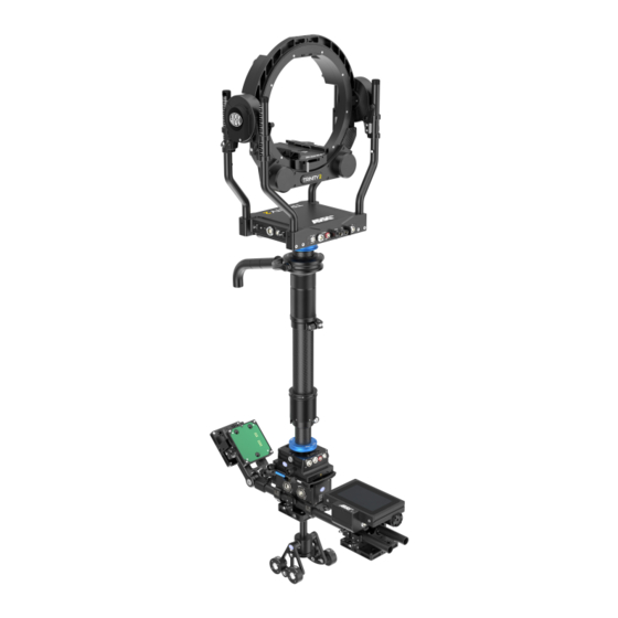
- Page 1 TRINITY 2 System U S E R M AN U A L 01.09.2022...
-
Page 2: Disclaimer
In no event shall ARRI or its subsidiaries be liable for or have a remedy for recovery of any special, direct, indirect, incidental, or consequential damages, including, but not limited to lost profits, lost savings, lost... -
Page 3: Imprint
The information and intellectual property contained herein is confidential between ARRI and the client and remains the exclusive property of ARRI. If you find any problems in the documentation, please report them to us in writing. ARRI does not warrant that this document is flawless. -
Page 4: Table Of Contents
Battery Mounting System Overview................45 Installation and Operation..................... 47 TRINITY Head Installation and Operation..............47 8.1.1 Installing TRINITY 2 Head................... 47 8.1.2 Installing SAM Dovetail Plates to TRINITY 2 Head............. 48 8.1.3 Installing the Camera to TRINITY 2 Head..............51 8.1.4 Height Adjustment......................53 8.1.5 Turning on the system....................54... - Page 5 Content 8.3.3 Gimbal Clamp Force Adjustment................. 62 Master Grip Trinity Installation and Operation..............63 8.4.1 Mounting the Master Grip TRINITY on the Gimbal............63 8.4.2 Mounting a Monitor Mount on the Master Grip TRINITY..........64 8.4.3 Mounting Transvideo Starlite Monitor................65 8.4.4 Mounting Small HD 503 Monitor.................. 66 8.4.5 Positioning of the Master Grip TRINITY...............67 RCP-3 Installation and Operation...................68...
- Page 6 Content Transportation and Storage...................89 Disposal........................... 90 ARRI Service Contacts....................91 Appendix.......................... 93...
-
Page 7: About This Document
About this Document About this Document This user manual is aimed at everyone involved in using the system and provides directions on how to operate it safely and as intended. To ensure safe and correct use, all users must read the user manual before using the accessories for the first time. -
Page 8: About The Product
Always follow the instructions and system requirements for all equipment involved. What is it? TRINITY 2 is a 5 axis hybrid camera stabilizer system, which enables very special camera movements including 360° rotation on the camera's lens axis. What does it do? Any influences from the movement of the user, which can negatively affect the image, are completely eliminated by the TRINTY 2 system. -
Page 9: Technical Data
About the product Technical Data TRINITY 2 Power supply 10,6 V – 33,6 V DC 12/24V max. 15A Weight 14.5 kg 31.9 lb Temperature range -20° C to +45° C -4° F to +113° F 95% humidity max. non condensing Storage temperature -30°... - Page 10 About the product TRINITY Head 2 (TRH-2)
- Page 11 About the product TRH-2 Interfaces 12V / 24V Lemo 2B 7pin 12/24V max. 15A Lemo 0B 2pin 12V max. 3A Fischer 3pin 12V max. 3A CAN Bus Fischer 4pin 12V max. 3A FS CAN Bus Fischer 4pin 12V max. 3A HD In / Monitor Out / Loop Analog Joystick In Lemo 1B 7pin...
- Page 12 About the product Center Post Center Post lengths: The Standard and Volt Post can be extended from 45.5cm / 17.92in to 71cm / 27.95in. artemis outer post diameter 48mm / 1.88in Volt outer post diameter 44.45mm / 1.75in Inner post diameter 38.1mm / 1.5in The Shorty Post can be extended from 37cm / 14.56in to 46.5cm / 18.30in.
- Page 13 About the product Master Grip TRINITY 1 and 2 (MGT-1 and MGT-2) MGT-1 & MGT-2 Interfaces Weight MGT-1 0.4 kg 8.88 lb Weight MGT-2 0.5 kg 1.10 lb LBUS Lemo 0B 4pin 12V max. 3A...
- Page 14 About the product Remote Control Panel 3 (RCP-3) RCP-3 Interfaces Weight 1.0 kg 2.2 lb Lemo 0B 2pin 12V max. 3A Fischer 3pin 12V max. 3A CAN Bus Fischer 4pin 12V max. 3A FS CAN Bus Fischer 4pin 12V max. 3A LBUS Lemo 0B 4pin 12V max.
- Page 15 About the product Top and Bottom Stage 2 (TST-2 and BST-2) TST-2 and BST-2 Interfaces Lemo 0B 2pin 12V max. 3A 12V/24V Lemo 2B 7pin 12/24V max. 15A HD-1 / HD-2 Fischer 3pin 12V max. 3A Lemo 1B 4pin 12V max. 3A LBUS Lemo 0B 4pin 24V max.
- Page 16 About the product Battery Hanger Module 2 (BHM-2) BHM-2 Interfaces Battery in 1 - 3 Lemo 2B 4pin 12/24V max. 20A Main Power Out Lemo 2B 7pin 12/24V max. 15A USB Port USB-Typ-A 5,2 V...
- Page 17 About the product Battery Mounting System Module 1 and 2 (BMS-1 and BMS-2) Model Voltage Weight Dimension K2.0040284 92 x 98 x 14mm 20.5 – 33.6V 99 g / 0.21 lb 3.62 x 3.85 x 0.55in B-Mount for BMS-2 K2.0040285 92 x 98 x 23mm 14.4 –...
-
Page 18: Pin Out
About the product Pin Out ARTEMIS 2 / TRINITY 2... -
Page 19: Scope Of Delivery And Warranty
Certifications and Safety Standards Approval Information The TRINITY 2 is approved for use in countries where the CE or FCC declaration is accepted. That contains the European Union, Canada, Japan and the USA. The import and use in other countries may be subject to legal, official or regulatory requirements and regulations. - Page 20 (EU) 2015/863 of March 31, 2015. The manufacturer bears sole responsibility for issuing this declaration of conformity. UK Declaration of Conformity Brand Name: ARRI Product Description: Camera Stabilizer SystemTRINITY 2 The designated products conform to the specifications of the following United Kingdom regulations: The Electromagnetic Compatibility Regulations 2016 (SI 2016 No.
-
Page 21: Safety Instructions
Safety Instructions Safety Instructions This safety information is in addition to the product specific operating instructions in general and must be strictly observed for safety reasons. Read and understand all safety and operating instructions before you operate or install the system. Retain all safety and operating instructions for future reference. -
Page 22: General Safety Instructions
Installation and operation may only be carried out by trained personnel who are familiar with the system. Observe accident prevention regulations. Do not place the TRINITY 2 on an unstable trolley or hand truck, stand, tripod, bracket, table or any other unstable support device. - Page 23 Using the TRINITY 2 in a humid environment and with condensation When moving TRINITY 2 from a cool to a warm location or when the TRINITY 2 is used in a damp environment, condensation may form inside the on internal or external electrical connections.
- Page 24 Disconnect the cables from the TRINITY 2 before moving. CAUTION Unhealthy posture or excessive physical exertion during operation Improper handling of the TRINITY 2 can lead to permanent physical injuries to the human locomotive system. Ensure an ergonomic posture when operating and carrying the TRINITY 2.
-
Page 25: Overview
Overview Overview... -
Page 26: Trinity 2 Head Overview
Overview TRINITY 2 Head Overview Front / right view... - Page 27 Overview Back / left view...
- Page 28 Overview Junction Box right side Junction Box left side...
- Page 29 Overview Front panel Panel Right Panel Back...
- Page 30 K2.0010476 HD SDI BNC Cable K2.0041984 12G HD SDI BNC Cable, 0,63m/25in Available joystick and video cables K2.0043861 TRINITY 2 Joystick Cable, 75cm/29.5in K2.0043975 TRINITY 2 Joystick Cable, 125cm/49in K2.0041984 12G HD SDI BNC Cable, 0,63m/25in K2.0044234 12G HD SDI BNC Cable, 0,84m/33in...
- Page 31 Overview What is it? TRINITY 2 is a 5 axis hybrid camera stabilizer system, which enables very special camera movements including 360° rotation on the camera's lens axis. What does it do? Any influences from the movement of the user, which can negatively affect the image, are completely eliminated by the TRINTY 2 system.
-
Page 32: Center Post Overview
Overview Center Post Overview Introduction The two-stage artemis 1.8" carbon center post offers a tool-free post clamp and a guided 1.8" inner telescopic post. Therefore, monitor brackets and existing accessories based on a 1.5in diameter can be used on with the artemis post. -
Page 33: Gimbal Overview
Overview Only the artemis 1.8in post offers the unique tool-free Fine Trim mechanism for precise length adjustment of the inner post. Finding the perfect drop down is now more than easy with the Fine Trim mechanism. After a filter or lens change, there is no longer a need to open the post or gimbal clamp to adjust the drop down. - Page 34 Overview...
-
Page 35: Master Grip Overview
Overview Master Grip Overview... - Page 36 Overview What is it? The Master Grip TRINITY is a new LBUS based joystick controller for the TRINITY Gen 2, which is available in two versions: MGT-1 with one joystick and three function keys MGT-2 with two joysticks and six function keys The Master Grip TRINITY is clamped to the handle of the artemis gimbal.
-
Page 37: Remote Control Panel Overview
Overview Remote Control Panel Overview What is it? The RCP-3 is a compact and lightweight remote control that is programmed and controlled by the user via a 5in touch panel. In addition to input through the touch panel, various values can also be programmed into the RCP-3 using four freely assignable encoders, turn-push encoders. - Page 38 Overview What does it do? The RCP-3 is used to set up and control the TRINITY Gen 2 system. Depending on the camera, lens and accessories used, parameters such as the power and torque of the motors of the TRINITY must be set to the total payload of the camera setup. The user can also program the general function, the speed and other parameters of the Master Grip TRINITY joystick via the RCP-3 to suit their personal preferences.
- Page 39 With the RCP-3 wireless mode, a second operator or the DOP can control the tilt and roll axis via the Digital Remote Wheels DRW-1 ARRI wheels. In addition, a technician can also take care of the PID and other settings, while the TRINITY operator...
-
Page 40: Top Stage And Bottom Stage Overview
Overview Top Stage and Bottom Stage Overview... - Page 41 Overview ATTENTION In the ARTEMIS 2 application, LBUS and CAN Bus are not used. The TST and BST are available in two versions: TST-1 & BST-1 TST-1& BST-1 is available as an upgrade for existing artemis and TRINITY systems using a LEMO 3B, 10pin, two video lines socket and main cable.
- Page 42 The exact front and rear and side-to-side adjustments can be made from either side of the Top Stage. So it doesn't matter if you are left handed or right handed. The modular design enables the user to carry out essential settings himself, as well as simple and fast service by the local ARRI service.
-
Page 43: Battery Hanger Module Overview
Overview Battery Hanger Module Overview What is it? The Battery Hanger Module Gen.2, BHM-2 is a future proof high-performance power supply for artemis and TRINITY camera stabilization systems. Regardless of the batteries used, whether 12V or 24V batteries, the BHM-2 always supplies 12V and 24V for the camera and the accessories used. What does it do? If 12V batteries are used, 24V will be transformed from the 12V if 24V power supply is required. - Page 44 Overview What problems does it solve? The modular design of the Battery Hanger Module, BHM-2 takes up to three Battery Mounting System, Gen. 2 (BMS-2), which can be placed easily and quickly in any desired position on the 19mm rods. The BHM-2 can handle different communication protocols and displays the battery information as long the batteries provides this kind of information.
-
Page 45: Battery Mounting System Overview
Overview Battery Mounting System Overview... - Page 46 Overview What is it ? The newly developed Battery Mounting System enables extremely flexible use and attachment of different battery types (B-Mount, V-Mount & G-Mount) on the TRINITY generation 1 and 2 and ARTEMIS generation 2. How does it work? The battery holder system consists of a base module with a the rod clamp mechanism to which three different battery holders can be attached quickly and easily.
-
Page 47: Installation And Operation
When using the system on camera cranes, a suitable safety rope must be used. Use only accessories approved by ARRI. The use of accessories not approved by ARRI is at your own risk. Please observe all relevant safety guidelines. -
Page 48: Installing Sam Dovetail Plates To Trinity 2 Head
Removing the Ring Main Cable while the TRINITY 2 head is powered on Risk of damage to the accessories. DO NOT remove the Ring Main Cable while the TRINITY 2 head is powered on. Post Assembly 4. Carefully place the TRINITY 2 head onto the 1.8in center post. - Page 49 Installation and Operation CAUTION Moving clamp lever without safety lock Risk of crushing fingers. Do not pull on the clamp lever before the safety lock has been released! Do not pull on the clamp lever and slide the safety latch at the same time! Safety Latch 2.
- Page 50 Using the SAM plates will speed up the camera setup and later the balancing process. The special hight of every SAM plate will lift the dedicated camera right into the center of the TRINITY 2 inner ring. This way a perfect COG of the camera is guaranteed.
-
Page 51: Installing The Camera To Trinity 2 Head
Installation and Operation K2.0038618 Stabilizer System Bracket SSB-2 15mm 8.1.3 Installing the Camera to TRINITY 2 Head Tilt-Lock 1. Move the Lock lever to the left in the Locked position. CAUTION Moving dovetail clamp mechanism lever without safety lock. Risk of crushing fingers. - Page 52 Installation and Operation COG / Fore and aft adjustment 8. Open the Tilt-Lock. 9. Move the camera forth and back until it reaches its center of gravity. Locking Clamp Lever 10. After the camera has reached the desired position / COG, push the clamp lever all the way to the right until the dovetail clamp mechanism is securely locked.
-
Page 53: Height Adjustment
Introduction In order to be able to move the camera and all components on the tilt axis through the TRINITY 2 head, the height of the tilt axis / tilt motors must be adjusted in relation to the rear length of the camera from the COG. -
Page 54: Turning On The System
Only use the Top Stage TST-2 in combination with the Battery Hanger Module BHM-2 for the internal power supply of the TRINITY 2 Head. Alternatively, an external power source can be used to power the TRINITY 2 head. DO NOT combine the internal with an external power supply! - Page 55 Installation and Operation CAUTION Automatically move to the home position Risk of crushing fingers. The camera / tilt and roll axis will automatically move to the home position, after turning on the stabilization. Make sure that your fingers do not get between the top cover and the camera while checking the tilt axis.
-
Page 56: Center Post Installation And Operation
Installation and Operation Center Post Installation and Operation 8.2.1 Center Post 1.8in Installation (Standard Post, Volt Post, Shorty Post, Super Post) Extending the Center Post Changing center post position: 1. Open the post clamp lever. 2. Slide or pull the inner post to the desired position. →... -
Page 57: Gimbal Installation And Operation
Installation and Operation ADVICE If the clamping force of the Center Post clamp weakens, clean the Inner Post with isopropanol, before you adjust the clamping force. Clamp Force Adjustment 1. Open the clamp lever. 2. Turn the silver nut by a 1/8 or 1/4 turn to the right, to adjust the clamp force. -
Page 58: Adding Components
Installation and Operation ADVICE Overtighten the center ring! May cause damage. Tighten the center carefully. It is not a clamp lever! 1. Tighten carefully the center ring. 2. Move the gimbal to the desired position by rotating and sliding the gimbal. 3. - Page 59 Installation and Operation ADVICE For a more permanent connection, apply two drops of Loctite 222 to the threads. 1. Hold the straight gimbal handle and turn the curved gimbal handle to remove the Curved Handle. Gimbal Handle Extender assembly 2. First screw the extender onto the straight handle. Curved Handle assembly 3.
- Page 60 Installation and Operation Knurled Grip Gimbal Extension, Ø1.8in (K2.0014280) Removing Centering Ring 1. Remove the Top Stage first. 2. Use the Post Tool (K2.0040046) to open the Centering Ring by turning it to the left. 3. Remove the Centering Ring from the Gimbal. Knurled Grip assembly 4.
- Page 61 Installation and Operation TIFFEN M1 / M2 Post Gimbal Inserts (K0.0040291) Removing Centering Ring 1. Remove the Top Stage first. 2. Use the Post Tool (K2.0040046) to open the Centering Ring by turning it to the left. 3. Remove the Centering Ring from the Gimbal. Removing the Delrin Sleeve 4.
-
Page 62: Gimbal Clamp Force Adjustment
Installation and Operation 8.3.3 Gimbal Clamp Force Adjustment ADVICE Overtighten the leveling screw This will cause the clamping force to become excessive and the Carbon Center Post may be damaged. Turn the silver nut by a 1/8 or 1/4 turn to the right. NOT more! ADVICE If the clamping force of the Gimbal clamp weakens, clean the Outer Post with isopropanol, before you adjust the clamping force. -
Page 63: Master Grip Trinity Installation And Operation
Installation and Operation Master Grip Trinity Installation and Operation 8.4.1 Mounting the Master Grip TRINITY on the Gimbal Gimbal Mounting Bracket 1. Before you begin, make sure the gimbal handle extension is also attached. 2. Open the clamp lever of the Mounting Bracket 3. -
Page 64: Mounting A Monitor Mount On The Master Grip Trinity
Installation and Operation 8.4.2 Mounting a Monitor Mount on the Master Grip TRINITY Mounting the 19mm rod 1. Loosen the mounting bracket clamp lever. 2. Slide the 19mm rod into the insert. Mounting the Monitor Adapter 3. There are two different monitor adapters to choose from: Monitor Adapter for Transvideo..K2.0014831 Monitor Adapter for Small HD..K2.0014832 4. -
Page 65: Mounting Transvideo Starlite Monitor
3. Tighten the screw at the back. Monitor Power 4. Connect the MTG Monitor Pwr, Lemo 0B, 5pin (K2.0038999) with the Transvideo / ARRI Starlite monitor and with the upper LBUS Socket at the Master Grip TRINITY. ATTENTION If you are using a standard Transvideo Starlite monitor with a 2pin Lemo socket, use the MTG Monitor Pwr, Lemo 0B, 2pin (K2.0038998). -
Page 66: Mounting Small Hd 503 Monitor
SmallHD monitor and with the upper LBUS Socket at the Master Grip TRINITY. Joystick Cable 5. Connect the TRINITY 2 Joystick Cable 75cm/29.5in (K2.0043861) with the lower LBUS Socket at the Master Grip TRINITY and with the LBUS Socket at the TRINITY 2 head. -
Page 67: Positioning Of The Master Grip Trinity
Installation and Operation 8.4.5 Positioning of the Master Grip TRINITY The Master Grip TRINITY MGT-1 & MGT-2 enables all segments, such as brackets, joysticks and handle, to be freely positioned in relation to each other. In this way, every user can position the Master Grip TRINITY, the joystick, the function keys and the monitor in the perfect position. -
Page 68: Rcp-3 Installation And Operation
Pushing away the clamping slide makes it easier to move the screws. 3. Tighten both screws. 8.5.2 Power ON / OFF To turn the RCP-3 ON and OFF, press and hold down the Jog- Wheel until the ARRI logo appears on the display. -
Page 69: Jog-Wheels
Installation and Operation 8.5.3 Jog-Wheels Once the Jog-Wheels have been assigned a function, these can be used to quickly and intuitively change values such as speed, ramp by turning the Jog-Wheel. At the same time, the button function allows you to turn ON / OFF functions such as: Home Position, True Tilt, True Pan, etc. -
Page 70: Tst And Bst Installation And Operation
This would cause more than the allowed amount of volts to flow through the ARTEMIS 2 and TRINITY 2. Risk of damage to the accessories. DO NOT power the TRINITY 2 Head, Top and Bottom Stage at the same time. Use for powering TRINITY 2 Head OR Top Stage OR the Bottom Stage. -
Page 71: Installing Sam Dovetail Plates
Installation and Operation 8.6.2 Installing SAM dovetail plates CAUTION Moving clamp lever without safety lock Risk of crushing fingers. Do not pull on the clamp lever before the safety lock has been released! Do not pull on the clamp lever and slide the safety latch at the same time! 1. - Page 72 Using the SAM plates will speed up the camera setup and later the balancing process. The special hight of every SAM plate will lift the dedicated camera right into the center of the TRINITY 2 inner ring. This way a perfect COG of the camera is guaranteed.
-
Page 73: Adjusting Clamping Force
Check that the clamping pads are clean. Remove dirt or grease with isopropanol. Check whether the clamping pads still cover the entire area. If parts of the clamp pads are gone, please contact ARRI Service. ADVICE Overtighten the leveling screw This will cause the clamping force to become excessive and the Clamp Pads may be dam- aged. -
Page 74: Battery Hanger Module Operation And Installation
Installation and Operation Battery Hanger Module Operation and Installation 8.7.1 Batter Hanger Module BHM-2 Mounting BHM-2 to TST / BST 1. Unlock and open the Top / Bottom Stage clamp mechanism. 2. Align the Battery Hanger Module dovetail with the Top / Bottom Stage mount. -
Page 75: Battery Mounting System
Installation and Operation 8.7.3 Battery Mounting System Installation BMS-2 1. Place the Battery Mount on the BMS Base. ATTENTION Make sure the location pin is aligned with the receiver hole and that the pogo pins line up with the receiver pads on the circuit board. 2. -
Page 76: Connecting The Battery Mounts To The Battery Hanger Module
Installation and Operation Free Positioning of the Battery Mounts The combination of the BHM, which is equipped with 19 mm rods, and the freely positionable battery system allows the size and weight distribution of the counterweight in the lower slide to be designed in an unprecedented way. -
Page 77: Connecting The Battery Hanger Module To The Top / Bottom Stage
Battery Hanger Module and the POWER IN socket of the Top / Bottom Stage. 8.7.7 Power ON / OFF To turn the BHM-2 / the entire system ON and OFF, press and hold down the Jog-Wheel until the ARRI logo appears on the display. -
Page 78: Jog-Wheel Functions
Installation and Operation 8.7.8 Jog-Wheel Functions Turning the jog-wheel takes you through the various status pages. A double click on the jog-wheel opens the menu. There you set up the Battery Hanger modes or carry out software updates in the System sub menu. Modes and functions can be selected and activated by turning and pressing the jog-wheel. -
Page 79: 8.7.10 Battery Status
Installation and Operation Switching ARTEMIS / TRINITY Mode 1. Double-click the jog-wheel 2. Turn the jog-wheel left to reach the current mode 3. Click the actual mode once 4. Select the mode you want, by clicking once 5. Or select Exit to cancel the action 8.7.10 Battery Status Home Screen BHM-2 This main page is displayed after switching on the BHM-2. - Page 80 Installation and Operation Turning the jog wheel takes you to this page. The current consumption in amp of the individual batteries can be read out here. All types of warnings are displayed in orange color. ADVICE Using 24V batteries Shutdown when the output voltage is less than 23.0 volts. Single battery warning when the voltage is less than 23.9 volts.
-
Page 81: General Working Method / Bhm-2
Installation and Operation ADVICE Using 12V batteries Shutdown when the output voltage is less than 11.0 volts. Single battery warning when the voltage is less than 11.9 volts. Single battery warning when percent reading is less than 20%. 24V Line warning when the output voltage is less than 11.9 volts. Low voltage warning when less than 10% of all batteries. -
Page 82: 8.7.12 Discharge Modes
Installation and Operation If 12V batteries and 24V batteries are connected, 12V will be supplied directly to the 12V consumers and 24V directly to 24V consumers. As soon as a 12V consumer is detected, the BHM-2 supplies a regulated 12 voltage to this consumer. As soon as a 24V consumer is detected, the BHM-2 supplies a regulated 24 voltage to this consumer. - Page 83 Installation and Operation Changing Battery Mode 1. Double-click the jog wheel 2. Select Battery Mode by clicking the jog-wheel once 3. Turn the jog wheel and select the desired discharge mode by clicking on the jog wheel once 4. Or select Exit to cancel the action...
-
Page 84: System Bhm-2
Installation and Operation 8.7.13 System BHM-2 Brightness To adjust the display brightness 1. Double-click the jog-wheel 2. Turn the jog wheel right to reach System and press the jog wheel to select 3. Turn the jog-wheel left to reach Brightness and press the jog wheel to select 4. - Page 85 Installation and Operation Firmware Info To read out the actual Firmware information 1. Double-click the jog-wheel 2. Turn the jog wheel right to reach System and press the jog wheel to select 3. Turn the jog-wheel to reach Firmware Info and press the jog wheel to select 4.
- Page 86 Installation and Operation Firmware Update 5. Dowload the latest firmware for the BHM-2 6. Copy it on a USB Stick (FAT32) 7. Insert the USB stick at the front of the BHM-2 8. Connect all three BMS-2 battery holders to the BHM-2 Battery Hanger Module! ADVICE Only in this way can new and updated battery communication...
-
Page 87: Battery Mounting System Operation And Installation
Installation and Operation Battery Mounting System Operation and Installation 8.8.1 Installation and Replacement of Battery Mounts 1. Place the Battery Mount on the BMS Base. ATTENTION Make sure the location pin is aligned with the receiver hole and that the pogo pins line up with the receiver pads on the circuit board. -
Page 88: Cleaning And Repair
Repairs carried out by Untrained Personnel Risk of electric shock and fire caused by short circuit. Do not try to repair the device yourself. Repairs may only be carried out by authorized ARRI service partners. For repairs and maintenance work on the camera system, please contact "ARRI... -
Page 89: Transportation And Storage
Follow the specified environmental conditions. Do not store the accessories in places where they may be subject to temperature extremes, direct sunlight, high humidity, severe vibration or strong magnetic fields. If you have any questions regarding the transport or storage of ARRI products, please contact "ARRI Service". -
Page 90: Disposal
Disposal Disposal ATTENTION The product can be returned to the manufacturer. This product falls within the scope of Directive 2012/19 / EU OF THE EUROPEAN PARLIAMENT AND OF THE COUNCIL of June 4, 2012 on waste electrical and elec- tronic equipment (WEEE II). Accordingly, this product must not be disposed of with household waste. -
Page 91: Arri Service Contacts
ARRI Service Contacts ARRI Service Contacts Arnold & Richter Cine Technik ARRI CT Limited / London GmbH & Co. Betriebs KG 2 Highbridge, Oxford Road Herbert-Bayer-Str. 10 UB8 1LX Uxbridge 80807 Munich United Kingdom Germany +44 1895 457 000 +49 89 3809 2121... - Page 92 ARRI Service Contacts CINEOM Broadcast DMCC. CINEOM Broadcast India Pvt. Ltd. Unit No. 2109, Jumeirah Bay Tower X2 Cluster X C-4, Goldline Business Centre Jumeirah Lakes Towers Link Rd. Malad West P.O Box 414659 400 064 Mumbai Dubai, UAE India...
-
Page 93: Appendix
Appendix Appendix RCP-3 Set K2.0041090 RCP-3, Remote Control Panel K2.0042837 CSS Clamp Bridge 52, 19mm K2.0043883 RCP-3, FS Can Bus Cable, 25cm/10i RCP-3 Accessories KK.0039984 RF-2400 Radio Module 2400 MHz FHSS Set (2x) K2.0033762 SRH FS CAN Bus Cable, 1m/3.2ft K2.0037701 SRH FS CAN Bus Cable, 5m/16.4ft K2.0019302...
Need help?
Do you have a question about the TRINITY 2 and is the answer not in the manual?
Questions and answers