Table of Contents
Advertisement
Quick Links
Advertisement
Table of Contents

Related Manuals for ARRI TRINITY Live


Summary of Contents for ARRI TRINITY Live
- Page 1 TRINITY Live OPERATING MANUAL April 2024 • 1.1 • English D4510007861...
- Page 3 In no event shall ARRI or its subsidiaries be liable for or have a remedy for recovery of any special, direct, indirect, incidental, or consequential damages, including, but not limited to lost...
- Page 4 The information and intellectual property contained herein is confidential between ARRI and the client and remains the exclusive property of ARRI. If you find any problems in the documentation, please report them to us in writing. ARRI does not warrant that this document is flawless.
-
Page 5: Table Of Contents
TRINITY Live Rig Overview ...................... 14 3.6.2 TRINITY Live Head Overview....................14 3.6.3 TRINITY Live Head Details....................... 15 3.6.4 TRINITY Live Top Stage / Battery Hanger Overview..............16 3.6.5 TRINITY Live Pinouts ....................... 18 3.6.6 TRINITY Wiring Diagram ......................20 Certifications and Safety Standards....................21 Mounting and Assembly.......................... -
Page 6: About This Document
Keep the operating manual, the user manual and all other operating and assembly instructions belonging to the device in a safe place for future reference and possible subsequent owners. For more details about the product, please Searchkeys: refer to the ARRI website at: TRINITY Live, K2.0047648 TRINITY live product page ARRI documentation portal... -
Page 7: Safety Instructions
NOTICE indicates a potentially harmful situation. If not avoided, the equipment or something in its surrounding may be damaged. Always follow the recommended measures to avoid this situation. HINT Not relevant to safety, HINT provides additional information to clarify or simplify a procedure. TRINITY Live Operating Manual... - Page 8 WARNING Falling System Parts Do not built up or assemble the TRINITY Live the wrong way. It can fall down and cause serious injuries and damage to the product or property. Installation and operation must only be carried out by approved persons who know the product.
- Page 9 Do not put the device on an unstable trolley or hand truck, stand, tripod, bracket, table or any other unstable support device. Always put the device on dedicated support devices. Use only accessories approved by ARRI. The use of accessories not approved by ARRI is at your own risk. Please obey all related safety guidelines. WARNING Overloading the TRINITY Live by Persons or Objects Risk of injury caused by the TRINITY Live tipping over.
- Page 10 NOTICE Powering the TRINITY Live Head, Top and Bottom Stage at the Same Time This would cause more than the allowed amount of volts to flow through the TRINITY Live. Risk of damage to the accessories. Only use the Top Stage TST-2 in combination with the Battery Hanger Module BHM-2 for the internal power supply of the TRINITY Live head.
-
Page 11: About This Product
TRINITY Live is a camera stabilizer system specifically designed for broadcast use. NOTICE All versions of the TRINITY Live and its accessories are intended exclusively for professional use. It must be used only by skilled and trained personnel. The product and its accessories must not be used by inexperienced users and without proper training. -
Page 12: Technical Data
3 | About This Product 3.5 Technical Data 3.5.1 Dimensions 14.96" 16.53" 50" 17.32" 5.11" TRINITY Live Operating Manual... -
Page 13: Specification
About This Product | 3 14.96" 7.87" 9.13" 16.53" 8.85" 9.92" 3.5.2 Specification Electrical requirements (Input voltage) 10.6 V - 33.6 V DC Power supply (head) Lemo 1B 4pin connector Weight 12.5 kg / 27.5 lb TRINITY Live Operating Manual... -
Page 14: Product Layout
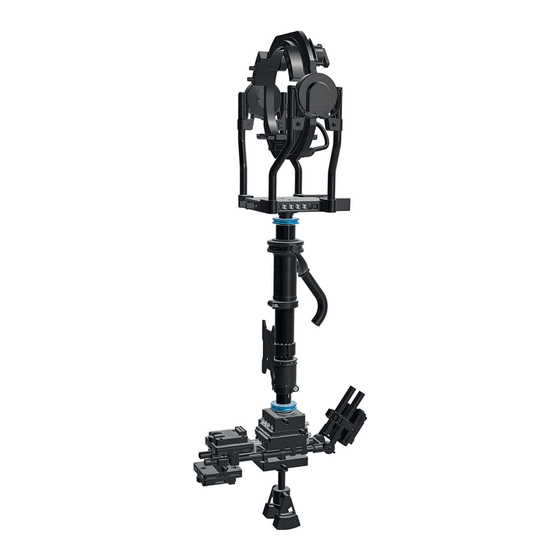
3 | About This Product 3.6 Product Layout 3.6.1 TRINITY Live Rig Overview 1 TRINITY Live Head 2 1.8" Carbon Post 3 1.8" Gimbal 4 Transmitter Bracket 5 BMS-1 Battery Mount 6 Pendulum 7 Docking Ring 8 Gimbal Handle 9 Post Fine Trim... -
Page 15: Trinity Live Head Details
14 SAM Dovetail Mount 15 Clamp Side-to-side Adjustment 16 SSB-5 Interface 17 Left Panel 18 Front Panel 3.6.3 TRINITY Live Head Details Left Junction Box 1 Not in use. For service only. 2 HD SDI In Right Junction Box 1 Camera Power 12 V, max. 10 A (24 V optional) -
Page 16: Trinity Live Top Stage / Battery Hanger Overview
2 HD SDI In 2 3 12 V / 24 V selector (optional) 4 HD SDI In 4 5 HD SDI In 3 3.6.4 TRINITY Live Top Stage / Battery Hanger Overview Front Side 1 Docking ring 2 Safety latch... - Page 17 Mini BNC 4 x 3G Video USB Mini For programming only External Power In Lemo 1S 4pin 12 V, max. 10 A TRINITY Live Interfaces Top Stage Interface Connector Specification Remarks 12 V / 24V Camera Lemo 1B 4pin 12 V / 24 V, max. 3 A...
-
Page 18: Trinity Live Pinouts
3 | About This Product 3.6.5 TRINITY Live Pinouts Camera Power Out Lemo 1B 304 Pin 1 +12 V Pin 2 Ground Pin 3 Ground Pin 4 + 12 V *Shown from mating side Focus Power Out Lemo 0S 304... - Page 19 *Shown from mating side Ext / Control Lemo 0B 306 Pin 1 Can Low ARRI Pin 2 Can High ARRI Pin 3 Can Low Pin 4 Can High Pin 5 +12 V Pin 6 Ground *Shown from mating side TRINITY Live Operating Manual...
-
Page 20: Trinity Wiring Diagram
Tally Gen.2 Set for TRINITY Gen.1, 3pin Lemo Ethernet (Analog Joystick) Tally Host K0.0050738 Tally Set for TRINITY Live Gen.1, 6pin Lemo (MGT Joystick) KK.0049712 Master Grip TRINITY 1 Pro Set Back / Left Camera Video Signal Tally Client Up to 4 x 3G HD SDI Video Lines Ext. -
Page 21: Certifications And Safety Standards
Essential requirements regarding No 1 EN 55032:2015/A11:2020; EN 55103-2:2009 Essential requirements regarding No 2 • EN IEC 63000:2018 Year of affixed CE-marking: 2023 TRINITY Live Operating Manual... -
Page 22: Mounting And Assembly
May damage persons, objects and property. Always use batteries with the same chemistry. Never use 24 V batteries. 4.1.1 Battery Mounts The TRINITY Live can be operated with the following battery mounts: K0.0044359 BMS-1 Upgrade Set, V-Mount, incl. 3 Mounts K0.0044359 BMS-1 Upgrade Set, Gold-Mount,... -
Page 23: To Wire The Battery Hanger / Top Stage
1. Connect the TRINITY 2 Joystick Cable 75cm/29.5in (K2.0043861) with the lower LBUS Socket at the Master Grip TRINITY and with the LBUS Socket at the TRINITY Live Front Panel. 2. Connect the MTG Monitor Pwr, Lemo 0B, 5pin (K2.0038999) for Transvideo / ARRI Starlite monitor, or 2pin Lemo socket, use the MTG Monitor Pwr, Lemo 0B, 2pin (K2.0038998) when... -
Page 24: Center Post Installation And Operation
Use only the appropriate cables, like: K2.0044413 Ethernet Cable, Lemo 1B 10pin to 0B 7pin, TRINITY Live K2.0044414 Ethernet Adapter Cable Lemo 1B 10pin to Lemo female 7pin, TRINITY Live K2.0048526 Ethernet Adapter Cable Lemo 1B 10pin - 10 Pin Cable, TRINITY Live Front /Right K2.0010681... -
Page 25: Gimbal Installation And Operation
1. Use the Post Tool to open the centering ring by turning it to the left. 2. Open the gimbal clamp lever. 3. Put the gimbal on the post. The Gimbal is ready for the positioning on the center post. TRINITY Live Operating Manual... - Page 26 Tighten the center carefully. It is not a clamp lever! 1. Tighten the center ring carefully. 2. Move the gimbal to the desired position by rotating and sliding the gimbal. 3. Lock the clamp lever. The Gimbal is positioned. TRINITY Live Operating Manual...
-
Page 27: Onboard User Interface
Onboard User Interface | 5 5 Onboard User Interface 5.1 Overview The following functions can be operated directly through the TRINITY Live Onboard User Interface: • Adjusting Roll axis / horizon • Mode / User preset selection (1-5) • Joystick menu / assigning the joystick, direction, speed, ramp, window. -
Page 28: To Assign The Master Grip Trinity Joystick
5.4 To Change Direction, Speed, Ramp and Window of the MGT Joysticks 5.5 To Change User Presets Press MODE once, to call up profile number ONE. Press MODE twice, to call up profile number TWO. And so on... TRINITY Live Operating Manual... -
Page 29: Cleaning, Maintenance And Repair
Risk of injury and damage. Do only carry out maintenance work that is describes in this operating manual. Do not try to repair the device yourself. Repairs may only be carried out by authorized ARRI service partners. For repairs and maintenance work on the device, please contact the ARRI Service. -
Page 30: Transportation, Storage And Disposal
PARLIAMENT AND OF THE COUNCIL of June 4, 2012 on waste electrical and electronic equipment (WEEE II). Accordingly, this product must not be disposed of with household waste. There are the respective country-specific disposal rules that must be observed. TRINITY Live Operating Manual... -
Page 31: Arri Service Contacts
ARRI Service Contacts | 8 8 ARRI Service Contacts Please see the current list of service partners at service contacts. Arnold & Richter Cine Technik GmbH & Co. ARRI CT Limited / London Betriebs KG 2 Highbridge, Oxford Road Herbert-Bayer-Str. 10... - Page 32 8 | ARRI Service Contacts ARRI China (Beijing) Co. Ltd. ARRI ASIA Limited Chaowai SOHO Tower C, 6/F, 0628/0656 41/F One Kowloon, 1 Wang Chaowai Dajie Yi 6 Yuen Street Kowloon Bay Beijing Hong Kong China P. R. China +86 10 5900 9680...
- Page 33 Notes TRINITY Live Operating Manual...
- Page 34 TRINITY Live Operating Manual...
- Page 35 TRINITY Live Operating Manual...
Need help?
Do you have a question about the TRINITY Live and is the answer not in the manual?
Questions and answers