
Related Manuals for ARRI 360 EVO


Summary of Contents for ARRI 360 EVO
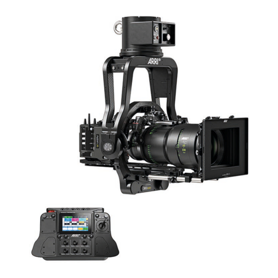
- Page 1 360 EVO Stabilized Remote Head OPERATING MANUAL January 2024 • English • Preliminary...
- Page 3 In no event shall ARRI or its subsidiaries be liable for or have a remedy for recovery of any special, direct, indirect, incidental, or consequential damages, including, but not limited to lost...
- Page 4 The information and intellectual property contained herein is confidential between ARRI and the client and remains the exclusive property of ARRI. If you find any problems in the documentation, please report them to us in writing. ARRI does not warrant that this document is flawless.
-
Page 5: Table Of Contents
Content Content 1 About this Document ..........................2 Safety Instructions ............................3 About the 360 EVO Remote Head ......................14 3.1 Intended Use............................14 3.2 Application Requirements ........................14 3.3 Identification ............................15 3.4 Environmental Conditions ........................15 3.5 Technical Data ............................16 3.6 Dimensional Drawing .......................... - Page 6 12 Remote Control Panel / Power Up ......................35 12.1 Remote Control Panel Hard Wiring....................... 35 12.2 Wireless Application..........................35 13 Emergency Stop ............................36 14 Cleaning, Repair and Disposal........................37 15 Transportation and Storage ........................39 16 ARRI Service Contacts ..........................40 360 EVO Operating Manual...
-
Page 7: About This Document
Keep the operating manual, the user manual and all other operating and assembly instructions belonging to the device in a safe place for future reference and possible subsequent owners. For more details about the product, please Searchkeys: 360 EVO, D45 1000 XXXX refer to the ARRI website at: ARRI documentation portal... -
Page 8: Safety Instructions
NOTICE indicates a potentially harmful situation. If not avoided, the equipment or something in its surrounding may be damaged. Always follow the recommended measures to avoid this situation. HINT Not relevant to safety, HINT provides additional information to clarify or simplify a procedure. 360 EVO Operating Manual... - Page 9 Clearly mark the movement area of the device with a barrier or a clearly visible marking (e.g. signal tape) on the floor. DANGER Rotating Parts DANGER DANGER Rotating Rotating Parts Parts DANGER Rotating Parts 360 EVO Operating Manual...
- Page 10 Risk of Injury through High Torque and Unbalanced Load Keep in mind that the 360 EVO stabilized remote head is a fully stabilized Gimbal based device with a payload capacity of up to 30 kg / 66 lbs. The amount of available torque is very high.
- Page 11 WARNING Falling System Parts Do not built up or assemble the 360 EVO the wrong way. It can fall down and cause serious injuries and damage to the device or property. Installation and operation must only be carried out by approved persons who know the device.
- Page 12 Do not put any not approved objects on the device. Do not hang any not approved objects on the device. Use only accessories approved by ARRI. The use of accessories not approved by ARRI is at your own risk. Please obey all related safety guidelines.
- Page 13 CAUTION Unhealthy Posture or too much Physical Exertion During Operation Improper handling of the 360 EVO bears risk of permanent long term physical damage to the human locomotive system. Keep an ergonomic posture when operating and carrying the 360 EVO.
-
Page 14: About The 360 Evo Remote Head
Many different camera and lens packages can be used with the 360 EVO and there are also many different ways to mount the remote head. Therefore, it is not always possible or practical to achieve perfect conditions in terms of rigidity and balance. -
Page 15: Identification
PID parameters. The correct adjustment of these PID values is crucial for the proper functioning of the system. An unbalanced camera setting puts more strain on the motors of the 360 EVO. The system requires more force to move the load, and this sometimes increases the possibility that the load will become unstable and that the remote head will overcompensate or wobble and oscillate. -
Page 16: Technical Data
3 | About the 360 EVO Remote Head 3.5 Technical Data Height 652 mm / 25.67 in Width 412 mm / 16.22 in Depth Head 150 mm / 5.9 in Depth Base 246 mm / 9.68 in Weight 11.6 kg / 25.57 lbs... -
Page 17: Scope Of Delivery And Warranty
• 1x K2.0049724, RCP-2 EVO Remote Control Panel • 1x K2.0049726, Case 360 EVO Stabilized Remote Head For scope of warranty, please ask your local ARRI Service Partner. ARRI is not liable for consequences from inadequate shipment, improper use or use of third-party products. -
Page 18: 360 Evo Remote Head Overview
4 | 360 EVO Remote Head Overview 4 360 EVO Remote Head Overview 4.1 Overview Back / Right Mounting Base for Mitchell Mount Pan Axis Eyebolt for safety rope Pan Axis Junction Box AUX Junction Box Threads Yoke for brackets... -
Page 19: Overview Front / Left
360 EVO Remote Head Overview | 4 4.2 Overview Front / Left Mounting base for Mitchell Mount Eyebolt for safety rope Pan Axis Junction box Pan Axis Controller Box Yoke Threads for brackets Tilt Lock Endstop Tilt Axis Tilt Axis... -
Page 20: Overview Left Junction Box
4 | 360 EVO Remote Head Overview 4.3 Overview Left Junction Box 12 V max. 3 A HDI SDI In 4.4 Overview Right Junction Box 12 V / 24 V Camera Power max. 15 A LBUS 12 V Aux Out Tally max. -
Page 21: Overview Junction Box Pan Axis
360 EVO Remote Head Overview | 4 4.6 Overview Junction Box PAN Axis HD SDI 12 V / 24 V Power In max. 15 A Motor ON / OFF FS CAN Emergency Knob Socket LBUS 4.7 Overview Ring Lower Back... -
Page 22: Interfaces
4 | 360 EVO Remote Head Overview 4.9 Interfaces 12 V / 24 V Camera Power Lemo 2B 7pin 12 V / 24 V max. 15 A LBUS Lemo 0B 4pin Data / 12 V max. 3 A Aux / Tally Fischer 3pin 12 V max. - Page 23 360 EVO Remote Head Overview | 4 CAN Bus FS Fischer 4pin (12 V max. 3 A) Pin 1 Ground Pin 2 CAN 1 Low Pin 3 CAN 2 High Pin 4 + 12 V *Shown from mating side 12 V / 24 V Power In Lemo 3B 7pin (12 V / 24 V max.
-
Page 24: Mounting And Assembly
The power supply for the EUT, has to provide "SELV" and a short-circuit-proof „limited power source", according to EN 60950-1. 5.2 Batteries (recommended) BEBOB CUBE 1200 www.bebob.de Anton Bauer CINE www.antonbauer.com VCLX Block Battery www.blockbattery.com Cinepower Magnum 60 www.cinepower.com 5.3 Wiring Power Supply 360 EVO Operating Manual... -
Page 25: 360 Evo Power Supply Cables
Mounting and Assembly | 5 5.4 360 EVO Power Supply Cables Use only appropriate cables, like: K0.0019478 SRH Power Supply Set, 600 W K2.0019303 SRH Power Supply Power and Data Cable, 12 V / 24 V, 20 m / 65.6 ft K0.0012269... -
Page 26: Remote Head Attachment
NOTICE In order to be able to use the maximum stabilisation performance of the 360 EVO, the remote head may only be mounted on cranes, dollies, towers, cable cams or other support suitable for use. -
Page 27: Camera Preparation
An activated TILT lock can cause damage due to overheating of the tilt motors. NOTICE The entire balancing procedure of the 360 EVO stabilized remote head is based on a symmetrical camera setup and neutral weight distribution. Only with a well executed camera preparation, a precise placement of the Center Of Gravity of the camera setup, the stabilized 360 EVO remote head can provide the best performance. -
Page 28: Camera Mounting
If the remote head control detects that one or more of its axes cannot be moved for more than 20 sec on the pan and tilt axis or 5 sec on the roll axis seconds, all motors are automatically switched off and a corresponding message is displayed on the remote control. 360 EVO Operating Manual... -
Page 29: Camera Connection
4pin XLR, 24 V 9.2 Camera Video Cables Use only appropriate cables, like: K2.0010476 HD SDI BNC Cable K2.0041984 12G HD SDI BNC Cable, 0,63 m / 25 in K2.0044234 12G HD SDI BNC Cable, 0,84m / 33 in 360 EVO Operating Manual... -
Page 30: Lbus Cables
Risk of Damage by Overloading the Power Source The 12 V auxiliary power consumption must not exceed 14.4 V / 3 Amps. Therefore, we do not recommend the use of D-Tab distributors, because they allow the connection of too many consumers. 360 EVO Operating Manual... -
Page 31: 360 Evo Remote Control Panel
360 EVO Remote Control Panel | 10 10 360 EVO Remote Control Panel Dimensions 10.08 14.56 3.46 All dimensions given in inch. 10.07 Width 370 mm / 14.56 in Depth 256 mm / 10.07 in Height 88 mm / 3.46 in (without joystick) Weight 3.1 kg / 6.83 lb (fully equipped) - Page 32 10 | 360 EVO Remote Control Panel Overview Top Button B1 Button B2 (analog / assignable) (analog / assignable) Emergency Stop Power ON / OFF Switch Knob K8 Knob K7 (analog / assignable) (analog / assignable) Joystick Standard Joystick Focus Wheel (optional) K2.0039880...
- Page 33 360 EVO Remote Control Panel | 10 LBUS In Mounting Rosettes ARRI Standard ARRI Standard 360 EVO Operating Manual...
-
Page 34: Interfaces Remote Control Panel Evp
*Shown from mating side CAN Bus FS Fischer 4pin (12 V max. 3 A) Pin 1 Ground Pin 2 CAN 1 Low Pin 3 CAN 2 High Pin 4 + 12 V *Shown from mating side 360 EVO Operating Manual... -
Page 35: Remote Control Panel / Power Up
SRH Power Supply Set for Remote Control Panel, V-Mount K0.0024195 SRH Power Supply Set for Remote Control Panel, Gold Mount K2.0048655 BMS-3, Battery Mounting Base, Gen.2, (naked) K2.0040286 V-Mount for BMS-1 / BMS-2 K2.0040285 Gold Mount for BMS-1 / BMS-2 K2.0040284 B-Mount for BMS-2 360 EVO Operating Manual... -
Page 36: Emergency Stop
An activated emergency stop switch will backlit by a red LED ring. Press the switch to deactivate the emergency stop. Remote Control Panel CAUTION Do not pull the emergency stop button! Turn the knob to the left to release the knob. 360 EVO Operating Manual... -
Page 37: Cleaning, Repair And Disposal
Repairs carried out by untrained persons Risk of electric shock and fire hazard caused by short circuit. Do not try to repair the device yourself. Repairs may only be carried out by a certified ARRI service center. 360 EVO Operating Manual... - Page 38 PARLIAMENT AND OF THE COUNCIL of June 4, 2012 on waste electrical and electronic equipment (WEEE II). Accordingly, this product must not be disposed of with household waste. There are the respective country-specific disposal rules that must be observed. 360 EVO Operating Manual...
-
Page 39: Transportation And Storage
Transportation and Storage | 15 15 Transportation and Storage NOTICE Improper Packing and Transportation of the 360 EVO Risk of damage to the product. Always follow the specified environmental conditions. Always transport the product and accessories in a suitable case. -
Page 40: Arri Service Contacts
16 | ARRI Service Contacts 16 ARRI Service Contacts Please see the current list of service partners at service contacts. Arnold & Richter Cine Technik GmbH & Co. ARRI CT Limited / London Betriebs KG 2 Highbridge, Oxford Road Herbert-Bayer-Str. 10... - Page 41 ARRI Service Contacts | 16 ARRI China (Beijing) Co. Ltd. ARRI ASIA Limited Chaowai SOHO Tower C, 6/F, 0628/0656 41/F One Kowloon, 1 Wang Chaowai Dajie Yi 6 Yuen Street Kowloon Bay Beijing Hong Kong China P. R. China +86 10 5900 9680...
- Page 42 Notes 360 EVO Operating Manual...
- Page 43 360 EVO Operating Manual...