Advertisement
Quick Links
Advertisement

Subscribe to Our Youtube Channel
Related Manuals for York Fitness YRK56040A


Summary of Contents for York Fitness YRK56040A
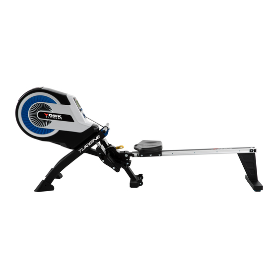
- Page 1 Owner’s Manual TURBINE ROWER Item # YRK 56040A www.yorkfitness.com.au ...
- Page 2 Table Of Contents Congratulations on CONTENTS purchasing your exercise Pack List equipment from Assembly Instructions 06 Console Operation Parts List Exploded Diagram You have chosen a high quality,safe and Warranty Innovative piece of equipment as your training partner and we are certain it will keep you motivated on the way to achieving your personal fitness goals.
- Page 3 For your benefit, read this manual carefully before you use the York Fitness Turbine Rower. To help us assist you, note the product model number and serial number before contacting us. Before reading further, please familiarize yourself with the parts that are labeled in the drawing below.
- Page 4 Rower Assembly Pack Checklist NO:1/91 NO:9 NO:54 NO:53 NO:45 NO:14L/R NO:55 NO:13 NO:35 NO:8L/R NO:11L/R NO:3 PART NO. DESCRIPTION Q’TY 1/91 Main frame/middle stabilizer Front support tube Rear support tube Seat Slide rail 14L/R Pedal (L/R) 11L/R Fixed bracket for handlebar (L/R) Roller Foot mat Allen bolt for pedal...
- Page 5 Rower Assembly Pack Checklist PART NO. DESCRIPTION Q’TY DRAWINGS Allen bolt Allen bolt Cushion rubber Spring washer Flat washer End cap for side rail (L) End cap for side rail (R) Axle for slide rail Allen bolt Flat washer Allen key (6MM) Wrench (13MM) Note: Above parts are all the parts needed to assemble this machine.
- Page 6 Rower Assembly Instructions Middle Stabilizer Rollers Attach the rollers (3) onto middle stabilizer, fasten with two sets of allen bolt (4) and nylon nut (2) which are pre-assembled on the middle stabilizer. www.yorkfitness.com.au ...
- Page 7 Attaching The Slide Rail Hardware Step 2 2 Allen Bolts (#34) 2 Spring Washers (#37) 2 Flat Washers (#38) 1 Axle (#41) 1 34 1. Pull out the ball pin (35) from the main frame (1). 2. Insert the slide rail (45) onto the U type connect tube of main frame (1), fasten with one axle for slide rail (41), two sets of allen bolts (34), spring washers (37) and flat washers (38).
- Page 8 Attaching the Seat and Rear Stabilizer Hardware Step 3 2 Cushioned Rubbers(#36) 2 Allen Bolts (#34) 1 Allen Bolt ((#19) 3 Flat Washers (#43) 2 Allen Bolts (#42) 2 End Caps (#40) 1. Insert the seat (53) to the slide rail (45). 2.
- Page 9 Attaching the Front Stabilizer Hardware Step 4 4 Allen Bolts (#19) 10 10 1. Turn over the main frame and place the rear support tube on the floor. 2. Take off four self-tapping screws (10) from the end caps for front stabilizer tube (8L/R) which are pre-assembled on the end caps, then attach the end caps to the front support tube (9) by four self-tapping screws (10).
- Page 10 Using the Lock Ball Pin 1.Turn over the main frame and place the front support tube on the floor. 2. Pull out the ball pin (35) from the main frame and unfold the slide rail(45). Then insert the ball pin (35) to the main frame again to lock in position.
- Page 11 Attaching the Pedals 1. Insert two fixed brackets for handlebar (11L/R) into the holes on the front support tube of main frame (1). 2. Attach the left pedal (14L) to the left side of main frame (1), fasten with two allen bolts (13). 3.
- Page 12 Attaching the Handlebar The handlebar (29) also can be placed into the Handlebar holder. Folding the Rower 1. To fold the machine for storage, the ball pin can be removed and the slide rail can be lifted up. Remember to replace the pin after folding the slide rail. ...
- Page 13 Battery Replacement 1. Loosen the 3 screws on the right side fo the console. Gently ease the console panel out of the shroud. 2. On the back panel, replace batteries. Make sure they fit tightly in the correct postions. 3. Place console back into shroud and retighten the 3 screws. ...
- Page 14 Operation of Your Console Key Functions BUTTONS: MODE: Select to change between the presets TIME, COUNT, DISTANCE, CALORIES, and PULSE. PULSE RECOVERY: ** It is functional only when used with the wireless chest belt (not included) ** The console has a Recovery Mode. This lets you monitor how quickly you recover from exercising.
- Page 15 setting is 0.1KMS. As soon as the target distance is achieved, a 3 second alarm will sound. COUNT: Accumulates total count from 0 up to 9999. You may also preset the target count before training by pressing “UP” and “DOWN” buttons. Each setting is 10 count. As soon as the target count is achieved, a 3 second alarm will sound.
- Page 16 Trouble Shooting Problem Cause Solution Batteries not Installed Install Batteries Monitor does not display Ensure the computer wires are Computer Wires not connected connected properly at the upright and computer Ensure the computer wires are connected Sensor wire not connected properly at the upright and the computer No speed or distance...
- Page 17 Part List Part Part Description Q'ty Description Q'ty Decorative cover for handlebar Main frame (Upper) Nylon nut M8 Handlebar Decorative cover for handlebar Roller (Lower) Allen bolt M8*35 Allen bolt M6*15 Square end cap 80*40 Self-tapping screw ST4*20 Non-slip pad Tension control knob Self-tapping screw ST4*15 Allen bolt M8*20...
- Page 18 Part Part Description Q'ty Description Q'ty Air duct (R) Spring clutch Air duct (L) Belt pulley Air damper Nylon nut M6 Nylon nut M12 Belt pulley bracket Flat washer Ф12.5*Ф25*2.2 Bearing 6000ZZ Wind turbine Clamp spring Ф10 Bearing 608ZZ Belt Pulley Self-tapping screw ST5*30 Tension rope...
- Page 19 www.yorkfitness.com.au ...
- Page 20 www.yorkfitness.com.au ...
- Page 21 WARRANTY, SAFETY AND ASSEMBLY INFORMATION YRK56040A IMPORTANT Please read and retain this manual as it will assist with identification for parts and service. ---------------------------------------------------------------------------------------------------------------------- BOYLES FITNESS warrants their Rower to be free from defects in material and workmanship under normal use and service conditions.
- Page 22 BFE Warranty Policy – November 1 2013 1. When purchased from an authorised BFE distributor the BFE warranty shall guarantee that all framework and components of your product are free from faulty manufacture. All faulty framework and components will be repaired or replaced as set out in this policy. All warranties in this policy apply to INDOOR HOME/DOMESTIC USE ONLY.
- Page 23 (b) Lack of general maintenance and or failure to service or maintain the equipment in accordance with the user manual specifications and recommendations. This includes alack of lubrication.Only use factory supplied lubricant. DO NOT USE WD40 or anything simular. You can purchase lubricant from your retailer or contact us directly at sales@boylesfitness.com.au (c) Power Surges.
- Page 24 Returned Goods: The unauthorised return of parts or product shall be refused and placed in the hands of the carrier at the cost of the shipper. Return authorisations can be obtained from BFE head office only. Additional Warranty If you would like to extend your labour warranty by 1 year ($99), 2 years ($199), 3 years ($299) please contact our office by emailing sales@boylesfitness.com.au (Not...
Need help?
Do you have a question about the YRK56040A and is the answer not in the manual?
Questions and answers