
Subscribe to Our Youtube Channel
Related Manuals for Kobold DAG-A1V


Summary of Contents for Kobold DAG-A1V
- Page 1 Operating Instructions Digital Indicating Unit for Panel Mounting Model: DAG-A1V Standard Signal 0/4-20 mA, 0-10 VDC...
-
Page 2: Table Of Contents
Error elimination ..................18 Disposal ...................... 19 EU Declaration of Conformance ..............20 Sold by: Kobold Messring GmbH Nordring 22-24 D-65719 Hofheim Tel.: +49(0)6192-2990 Fax: +49(0)6192-23398 E-Mail: info.de@kobold.com Internet: www.kobold.com page 2 DAG-A1V K06/0722... -
Page 3: Note
Please read these operating instructions before unpacking and putting the unit into operation. Follow the instructions precisely as described herein. The instruction manuals on our website www.kobold.com are always for currently manufactured version of our products. Due to technical changes, the instruction manuals available online may not always correspond to the product version you have purchased. -
Page 4: Brief Description
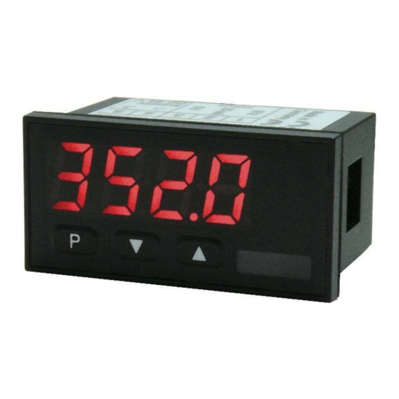
DAG-A1V 5. Brief description The panel instrument DAG-A1V is a 4-digit device for direct voltage and direct current signals and a visual limit value monitoring via the display. The configuration happens via three front keys. An integrated programming interlock prevents unrequested changes of the para-meter and can be unlocked again via an individual code. -
Page 5: Electrical Connection
DAG-A1V 7. Electrical Connection Type DAG-A1V3000R – supply of 24 VDC galvanically isolated Connection examples: Below you find some connection examples, which demonstrate some practical applications: DAG-A1V K06/0722 page 5... -
Page 6: Function Description And Operation
Level Button Description Change to parameterization level with the relevant parameters Menu level For navigation at the menu level To confirm the changes made at the parameterization level Parameterization level To change the value or setting page 6 DAG-A1V K06/0722... -
Page 7: Setting Up The Device
9.2 Standard parameterization: To be able to parameterize the display, press the [P] key in operating mode for 1 second. The display then changes to the menu level with the first menu item TYPE. DAG-A1V K06/0722 page 7... -
Page 8: Programming Interlock Run
9.3 Programming interlock RUN 9.4 Extended parameterization By pressing the [▲] & [▼] buttons during standard parameterization for one second, the display switches to the extended parameterization mode. Operation is the same as in standard parameterization. page 8 DAG-A1V K06/0722... - Page 9 DAG-A1V DAG-A1V K06/0722 page 9...
- Page 10 DAG-A1V page 10 DAG-A1V K06/0722...
-
Page 11: Reset To Default Values
• With reset, the default values of the program table are loaded and used for subsequent operation. This puts the unit back to the state in which it was supplied. Caution! All application-related data are lost. DAG-A1V K06/0722 page 11... -
Page 12: Functional Principle Of The Switching Points
An activated setpoint can be optically indicated by flashing of the 7-segment display. Functional principle of the alarms Alarm Deactivated, display value Threshold Threshold/limit value for switch over Hysteresis Width of the window between the thresholds Operating principle Limit value exceedance / limit value undercut page 12 DAG-A1V K06/0722... -
Page 13: Technical Data
100 ppm / K Measuring time 0.1…10.0 seconds Measuring principle U/F-conversion Resolution approx. 18 Bit at 1s measuring time Power pack 24 VDC ± 10 % max. 1 VA Memory EEPROM Data life ≥ 100 years at 25°C DAG-A1V K06/0722 page 13... - Page 14 Ambient conditions Working temperature 0°C…60°C Storing temperature -20°C…80°C Weathering resistance relative humidity 0-80% on years average without dew EN 61326 CE-sign Conformity to directive 2014/30/EU Safety standard According to low voltage directive 2014/35/EU EN 61010; EN 60664-1 page 14 DAG-A1V K06/0722...
-
Page 15: Order Codes
13. Order Codes STANDARD TYPES ORDER NUMBER Direct current / Direct voltage Housing size: 48x24 mm DAG-A1V3000R Options – breakdown of order code: DAG-A1V 3 0 0 0 R Supply 3 = 24 VDC, galvanic separated Output 0 = without Sensor supply... -
Page 16: Safety Advice
(normally signal ground). The device is not suitable for installation in areas where there is a risk of • explosion. Any electrical connection deviating from the connection diagram can • endanger human life and/or can destroy the equipment. page 16 DAG-A1V K06/0722... - Page 17 • appropriate point (normally earth or machines ground). So, a lower disturbance sensibility against impacted energy can be reached and dangerous potentials, that can occur on long lines or due to faulty wiring, can be avoided. DAG-A1V K06/0722 page 17...
-
Page 18: Error Elimination
The device does not react as • If you are not sure if the device has been expected. parameterised before, then follow the steps as written in chapter 10 and set it back to its delivery status. page 18 DAG-A1V K06/0722... -
Page 19: Disposal
(Cd, Hg, Li or Pb) of the heavy metal that is decisive for the classification as containing pollutants: 1. „Cd" stands for cadmium 2. „Hg" stands for mercury 3. „Pb" stands for lead 4. „Li" stands for lithium Electrical and electronic equipment DAG-A1V K06/0722 page 19... -
Page 20: Eu Declaration Of Conformance
DAG-A1V 17. EU Declaration of Conformance We, KOBOLD Messring GmbH, Hofheim-Ts, Germany, declare under our sole responsibility that the product: Digital Indicating Unit for Panel Mounting Model: DAG-A1V to which this declaration relates is in conformity with the standards noted below:...
Need help?
Do you have a question about the DAG-A1V and is the answer not in the manual?
Questions and answers