Hoppe AUDIO MINI Installation Instructions & Owner's Manual
Off-road sound system for yamaha wolverine rmax2 / rmax4 / x2 / x4 models
Hide thumbs
Also See for AUDIO MINI:
- Installation instructions & owner's manual (21 pages) ,
- Installation instructions manual (18 pages) ,
- Installation instructions and owner's manual (18 pages)

Subscribe to Our Youtube Channel
Related Manuals for Hoppe AUDIO MINI


Summary of Contents for Hoppe AUDIO MINI
- Page 1 INSTALLATION INSTRUCTIONS / OWNER’S MANUAL: AUDIO MINI OFF-ROAD SOUND SYSTEM FOR YAMAHA WOLVERINE RMAX2 / RMAX4 / X2 / X4 MODELS www.hoppeindustries.com 22667 FM 15 Troup, TX 75789 (262) 552-2770...
- Page 2 It is critical that proper eye wear, ear protection, and protective clothing is worn throughout the top installation. When you receive your Audio Mini off-road sound system, please check to ensure that all parts and hardware are included. If there are any parts missing or if you have any questions concerning the system at this time call Hoppe at (262)-552-2770 Mon-Thur.
-
Page 3: Table Of Contents
TABLE OF CONTENTS SECTION 1 – Tools Required .................... 4 SECTION 2 – About your Audio Mini sound system ............4 2.1 Applicable Year Models: ..................4 2.2 Audio Equipment Details: ..................4 2.3 Warranty: ........................5 2.4 Care and Maintenance: ..................... 5 2.5 Warnings: ........................ -
Page 4: Section 1 - Tools Required
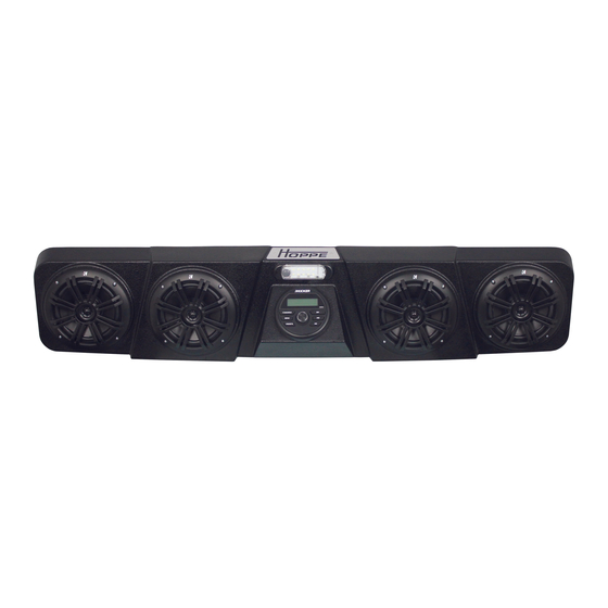
SECTION 2 – About your Audio Mini sound system 2.1 Applicable Year Models: This Audio Mini off-road sound system is designed to fit the following Wolverine models: 2021-2022 Wolverine RMAX2 1000 (all versions) 2021-2022 Wolverine RMAX4 1000 (all versions) ... -
Page 5: Warranty
2.3 Warranty: Your Audio Mini comes equipped with a 1 year limited warranty covering the light, the stereo equipment, and the enclosure. The date of warranty coverage will be determined by the registration date of the warranty card or online warranty registration. - Page 6 or side hill, acceleration, and braking performance will be negatively impacted by the weight of the sound system. Do not listen to your stereo at an uncomfortable volume for extended periods of time. Potential hearing loss may result. Revision - 6 of 17...
-
Page 7: Section 3 - Pre-Installation Inspection
SECTION 3 – Pre-Installation Inspection Included in your off-road sound system are the following components: Pre-assembled Audio Mini off-road sound system (All speakers and electronics come preinstalled with interior wire harness.) Chassis wire harness Mounting brackets Hardware bag ... -
Page 8: Section 4 - Installation
SECTION 4 – Installation 1. Place the provided loop clamps in the approximate mounting location on the roll bars. The Audio Mini brackets will rest on the loop clamps and be tightened in the following steps. See Figure 2. Figure 2: Approximate locations of the loop clamps. - Page 9 4. Use the supplied 3/8”-16 x 1” bolts, washers, and nylock nuts to secure the loop clamps to the mounting brackets. Snugly tighten the bolts to still allow for adjustment of the Audio Mini placement. See Figure 5. Note: Driver side bracket shown. (Passenger side similar) Figure 5: Hardware for mounting the loop clamps to the brackets.
- Page 10 See Figure 6 and Figure 7. Figure 6: Install the ¼”-20 bolts and washers to mount the Audio Mini to the brackets. Figure 7: Loosely install the sound system on the mounting brackets.
- Page 11 Figure 8: Up-down positioning of the Audio Mini. 8. Remove the hood from the front of the vehicle by lifting and rotating the lock knobs, lifting to release the 4 bosses, and sliding towards the front of the vehicle. See Figure 9.
- Page 12 Figure 10: Remove the torx screws and plastic panel. 10. Route the end of the chassis harness with the mating connector for the Audio Mini along with the wire bundle under the dash toward the driver’s front down tube opening. See Figure 11.
- Page 13 Gently lift the dash panel, pull the chassis harness connector through the opening, and connect it to the mating connector on the Audio Mini. The harness will be secured to the inside of the cage tube at the end of the installation. See Figure 12.
- Page 14 ACCESSORY CONNECTORS Figure 13: Accessory connectors for ignition power source. 13. Connect the chassis harness to the accessory connector, and replace the plastic panel. See Figure 14. ACCESSORY CONNECTION Figure 14: Connect accessory connector and replace the plastic panel. Revision - 14 of 17...
- Page 15 14. Connect the chassis harness battery cables to the battery, clamping the cables on top of any existing cables with the factory hardware. Connect the red harness wire to the terminal with the existing red battery cable (+ 12V). Connect the black harness wire to the terminal with the existing black battery cable (- 12V).
- Page 16 Figure 16: Secure the chassis harness under the hood. Figure 17: Secure the chassis harness to the frame tube. 16. Reinstall the torx screws and hood. See Figure 9, Figure 10, and Figure 12. Revision - 16 of 17...
- Page 17 17. You are now ready to enjoy the music and lighting provided by your Audio Mini off-road sound system. Basic operation works as follows: Turn the vehicle ignition switch on to power up the stereo system. (You must press the power button for first time connections or if the power was previously turned off manually.)
Need help?
Do you have a question about the AUDIO MINI and is the answer not in the manual?
Questions and answers