Hoppe AUDIO MINI Installation Instructions & Owner's Manual
Hide thumbs
Also See for AUDIO MINI:
- Installation instructions & owner's manual (21 pages) ,
- Installation instructions manual (18 pages) ,
- Installation instructions and owner's manual (18 pages)

Related Manuals for Hoppe AUDIO MINI


Summary of Contents for Hoppe AUDIO MINI
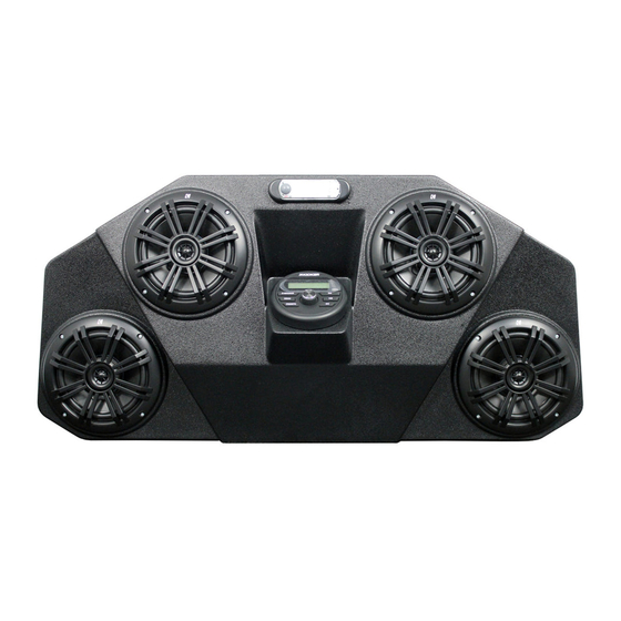
- Page 1 INSTALLATION INSTRUCTIONS / OWNER’S MANUAL: AUDIO MINI OFF-ROAD SOUND SYSTEM FOR KAWASAKI TERYX KRX 1000 MODELS www.hoppeindustries.com 22667 FM 15 Troup, TX 75789 (262) 552-2770...
- Page 2 It is critical that proper eye wear, ear protection, and protective clothing is worn throughout the installation. When you receive your Audio Mini off-road sound system, please check to ensure that all parts and hardware are included. If there are any parts missing or if you have any questions concerning the system at this time call Hoppe at (262)-552-2770 Mon-Thur.
-
Page 3: Table Of Contents
TABLE OF CONTENTS SECTION 1 – Tools Required .................... 4 SECTION 2 – About your Audio Mini sound system ............4 2.1 Applicable Year Models: ..................4 2.2 Audio Equipment Details: ..................4 2.3 Warranty: ........................5 2.4 Care and Maintenance: ..................... 5 2.5 Warnings: ........................ -
Page 4: Section 1 - Tools Required
SECTION 2 – About your Audio Mini sound system 2.1 Applicable Year Models: This Audio Mini off-road sound system is designed to fit the following Kawsaki Teryx KRX 1000 models: 2021-2022 Teryx KRX 1000 (all versions) ... -
Page 5: Warranty
2.3 Warranty: Your Audio Mini comes equipped with a 1 year limited warranty covering the light, the stereo equipment, and the fiberglass enclosure. The date of warranty coverage will be determined by the registration date of the warranty card or online warranty registration. -
Page 6: Warnings
2.5 Warnings: This off-road system adds up to 25 lbs. to your vehicle and is located up high on the roll cage. This increases the vehicle’s center of gravity and changes the vehicle dynamics and handling characteristics. Use extra caution as you learn the driving characteristics of your vehicle with your new off-road sound system installed. -
Page 7: Section 3 - Pre-Installation Inspection
SECTION 3 – Pre-Installation Inspection Included in your off-road sound system are the following components: Pre-assembled Audio Mini off-road sound system (All speakers and electronics come preinstalled with interior wire harness.) Chassis wire harness Mounting brackets Hardware bag ... -
Page 8: Section 4 - Installation
Figure 2: Remove the factory cross member bolt. 2. Place the provided loop clamps in the approximate mounting locations on the outside roll bars. The Audio Mini brackets will rest on the loop clamps and be secured in the following steps. See Figure 3. - Page 9 4. Use the supplied 3/8”-16 x 1” bolts, washers, and nylock nuts to secure the loop clamp to the mounting bracket. Snugly tighten both the loop clamp bolt and the front cross member bolt, waiting to fully tighten them until the Audio Mini is in the final desired position. See Figure 5.
- Page 10 6. Remove the center dash by popping out the six plastic rivets and removing the two screws shown in Figure 6 and Figure 7. The plastic rivets are released by first prying the center head up then pulling the entire rivet out. Figure 6: Remove the plastic rivets in the center dash.
- Page 11 Figure 7: Remove the plastic rivets and screws in the center dash. 7. Remove the corrugated tube cap at the front passenger side fire wall. Route the front end of the battery jumper wire, shown in Figure 8, into the opening toward the dash where the radiator tube goes through the fire wall and the other end into the corrugated tube.
- Page 12 INTO DASH AREA CORRUGATED TUBE Figure 9: Wire goes into corrugated tube and into dash area. 8. Remove the corrugated tube cap at the battery under the driver’s seat. Route the battery jumper wire from the front of the vehicle to the battery, through the corrugated tube.
- Page 13 10. Route the chassis harness behind the instrument cluster and across the upper dash frame tube toward the driver’s side front down tube as shown in Figure 12. Loosely zip tie the harness to the dash frame tube until the Audio Mini is secured in its desired position.
- Page 14 TOWARD DOWN TUBE ACROSS DASH FRAME TUBE Figure 12: Route chassis harness toward driver's side down tube. 11. Remove the plastic rivet by the driver’s front down tube, and route the end of the chassis harness up through the panels as shown in Figure 13. Revision - 14 of 20...
- Page 15 REMOVE PLASTIC RIVET Figure 13: Chassis harness routing under panels up to the down tube. 12. Route the harness up the frame tube as shown in Figure 14. Loosely zip tie the harness at the indicated locations, leaving room for adjustment until the final position is achieved.
- Page 16 Figure 14: Chassis harness routing up driver’s front down tube. 13. Using an assistant to support the weight of the Audio Mini, connect the mating connector on the chassis harness to the harness exiting out of the top of the Audio Mini on the driver's side.
- Page 17 Figure 15: Install the ¼”-20 bolts and washers to mount the Audio Mini to the brackets. Figure 16: Loosely install the sound system on the mounting brackets. 15. Slots in the sides of the Audio Mini brackets allow up-down movement, while the slots in the front of the brackets allow front-back movement to achieve your desired position.
- Page 18 Figure 17: Adjustable up-down positioning of the Audio Mini. FRONT SLIDE LOOP CLAMP ON TUBE REAR Figure 18: Adjustable front-back positioning of the Audio Mini. Revision - 18 of 20...
- Page 19 19. Reinstall the plastic pop rivet by the driver’s front down tube seen in Figure 13. 20. You are now ready to enjoy the music and lighting provided by your Audio Mini off-road sound system. Basic operation works as follows: ...
- Page 20 To learn about the more advanced features and operation of your stereo, visit the Kicker website links found in SECTION 2 – About your Audio Mini sound system of this document. Thank you for choosing the Hoppe Audio Mini off-road sound system for your Kawasaki Teryx KRX UTV.
Need help?
Do you have a question about the AUDIO MINI and is the answer not in the manual?
Questions and answers