Viessmann Divicon Installation Instructions Manual
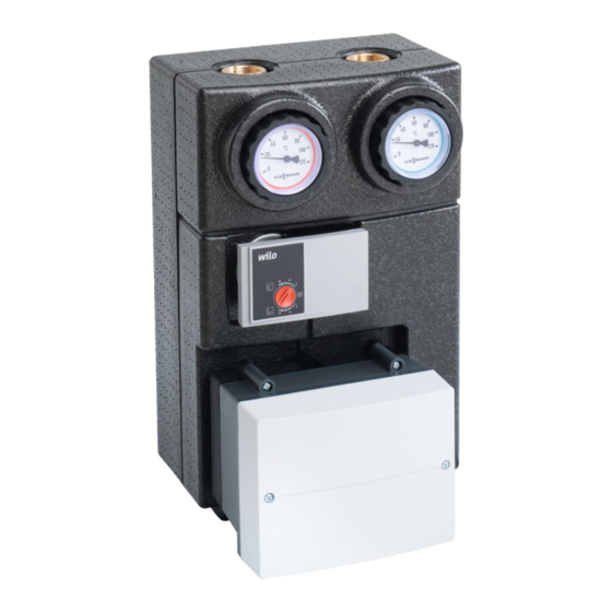
Heating circuit distributor
Hide thumbs
Also See for Divicon:
- Installation instructions manual (32 pages) ,
- Installation instructions manual (36 pages) ,
- Installation instructions for contractors (64 pages)

Related Manuals for Viessmann Divicon


Summary of Contents for Viessmann Divicon
- Page 1 VIESMANN Installation instructions for contractors Divicon Heating circuit distributor Divicon 5836498 GB 10/2021...
- Page 2 Safety instructions Please follow these safety instructions closely to prevent accidents and material losses. Safety instructions explained Danger Note This symbol warns Details identified by the against the risk of word "Note" contain addi- injury. tional information. Please note This symbol warns against the risk of material losses and environmental pollu-...
- Page 3 Safety instructions (cont.) Regulations to be observed ■National installation reg- ■Codes of practice of the ulations relevant trade associa- ■Statutory regulations for tions the prevention of acci- ■Relevant country-spe- dents cific safety regulations ■Statutory regulations for environmental protection Working on the system ■Where gas is used as Danger the fuel, close the main...
- Page 4 Repair work Please note Replace faulty com- Repairing compo- ponents only with nents that fulfil a genuine Viessmann safety function can spare parts. compromise the safe operation of the sys- tem.
-
Page 5: Table Of Contents
Filling the system....................19 Fitting the thermal insulation................20 ■ Low loss header (if supplied)................20 ■ Manifold......................21 ■ Divicon with mixer..................... 22 ■ Divicon without mixer..................23 Extension kit with mixer PCB................26 ■ Overview of electrical connections..............26 ■... -
Page 6: Disposal Of Packaging
Disposal of packaging Please dispose of packaging waste in line with statutory regulations. -
Page 7: Symbols
Symbols Sym- Meaning Reference to other document containing further information Step in a diagram: The numbers correspond to the order in which the steps are carried out. Warning of material losses and environmental pollution Live electrical area Pay particular attention. ■... -
Page 8: Spare Parts Lists
Spare parts lists Information about spare parts can be found at www.viessmann.com/etapp or in the Viessmann spare part app. -
Page 9: Preparing For Installation
Preparing for installation Removing the thermal insulation... -
Page 10: Wall Mounting
Wall mounting Fitting a single module (without manifold) Ø 10... - Page 11 Wall mounting (cont.) A Heating flow B Heating return...
-
Page 12: Fitting Several Modules With Manifold (Accessories)
Wall mounting (cont.) Fitting several modules with manifold (accessories) Ø 10 A Manifold for 2 Divicons B Manifold for 3 Divicons... - Page 13 Wall mounting (cont.) Manifold (H = 70 mm) for 2 Divicons A Heating flow B Heating return...
- Page 14 Wall mounting (cont.) Manifold (H = 100 mm) for 2 Divicons A Heating flow B Heating return...
- Page 15 Wall mounting (cont.) Manifold (H = 70 mm) for 3 Divicons A Heating flow B Heating return...
- Page 16 Wall mounting (cont.) Manifold (H = 100 mm) for 3 Divicons A Heating flow B Heating return...
- Page 17 Wall mounting (cont.)
- Page 18 Wall mounting (cont.) Low loss header (if supplied) A Heating flow B Heating return...
-
Page 19: Filling The System
Filling the system 1. For filling (with heating water), open 2. For operation, position the slot of the check valve in the heating the screw in the horizontal position. return by positioning the slot of the screw in the vertical position. Note Observe the marking on the adjust- ing screw. -
Page 20: Fitting The Thermal Insulation
Fitting the thermal insulation Low loss header (if supplied) -
Page 21: Manifold
Fitting the thermal insulation (cont.) Manifold... -
Page 22: Divicon With Mixer
Fitting the thermal insulation (cont.) Divicon with mixer Note With several Divicons, first fit the ther- mal insulation on the right-hand Divi- con. For the remaining Divicons, fit the insulation from right to left A Cut off if fitting a single module to B Cut out the thermal insulation if the wall. -
Page 23: Divicon Without Mixer
Fitting the thermal insulation (cont.) Divicon without mixer Note With several Divicons, first fit the ther- mal insulation on the right-hand Divi- con. For the remaining Divicons, fit the insulation from right to left... - Page 24 Fitting the thermal insulation (cont.) A Cut off if fitting a single module to B Cut out the thermal insulation if the wall. connecting with a union nut.
- Page 25 Fitting the thermal insulation (cont.)
-
Page 26: Extension Kit With Mixer Pcb
Extension kit with mixer PCB Note Bundle individual wires from the con- necting cables directly below the plugs. Secure with cable ties. Overview of electrical connections [{{] fÖ sÖ L ? N L ? N 230 V~/50 Hz Plug 230 V~ Please note P1 sÖ... -
Page 27: Rotary Switch S1
Extension kit with mixer PCB (cont.) Rotary switch S1 If several mixer extension kits are being connected, set rotary switch S1. -
Page 28: Connecting The Plusbus To The Heat Generator Control Unit
Extension kit with mixer PCB (cont.) Set the rotary switch on each extension Note kit to a consecutive number: If additional EM-P1 extensions are con- ■ Heating circuit with mixer M2: Rotary nected, always set the subscriber num- switch to 1 bers for the EM-P1 extensions to con- ■... -
Page 29: Power Supply
Extension kit with mixer PCB (cont.) Power supply Power supply at heat generator Connect the power cable to the exten- sion. Route the power cable to the heat gen- erator and connect to plug aBH. Observe the fuse protection of the con- tact (output) on the heat generator. - Page 30 Extension kit with mixer PCB (cont.) Danger Isolators for non-earthed conductors Incorrect electrical installations ■ The mains isolator (if installed) must can lead to serious injury from simultaneously isolate from the mains electrical current and result in all non-earthed conductors with a appliance damage.
- Page 31 Extension kit with mixer PCB (cont.) Connect the power supply in accord- ance with the diagram. If the power supply to the appliance is connected with a flexible power cable, ensure that the live conductors are pulled taut before the earth conductor in the event of strain relief failure.
-
Page 32: Connecting Several Accessories
Extension kit with mixer PCB (cont.) Connecting several accessories Power supply and PlusBus connection Power supply to all accessories via heat generator control unit Some accessories with direct power supply Heat generator control unit Further accessories Mixer extension kit for heating ON/OFF switch circuit with mixer M2 (electron- fÖ... - Page 33 Extension kit with mixer PCB (cont.) ■ In the following circumstances, use the contact (output) of the accesso- ries only to switch an on-site relay: An actuator with a higher power demand than the fuse rating required for the accessories, e.g. a circulation pump, is connected to the contact (output) of the accessories.
-
Page 34: Connection And Wiring Diagram
Extension kit with mixer PCB (cont.) Connection and wiring diagram A1 Mixer extension kit, ADIO control S1 Rotary switch unit A2 PCB F1 Fuse... -
Page 35: Changing The Rotational Direction (If Required)
Extension kit with mixer PCB (cont.) 230 V~ plugs No function P1 sÖ Heating circuit pump TS3 ) Low loss header temperature sensor (separate accessories) P3 gS Mixer motor PlusBus connection for con- Power supply 230 V/50 Hz fÖ necting to the heat generator Power supply for accessories fÖA and another accessory... -
Page 36: Specification
Specification Rated voltage 230 V∼ Rated frequency 50 Hz Rated current Power consumption 5.5 W Protection class IP rating IP 20 D to EN 60 529; ensure through design/installation. Permissible ambient temperature ■ During operation 0 to +40 °C ■ During storage and transport –20 to +65 °C Rated relay output breaking capacity ■... - Page 37 Specification (cont.) Curve Temperature in °C...
-
Page 38: Declaration Of Conformity For Extension Kit
Declaration of conformity for extension kit We, Viessmann Climate Solutions SE, Using the serial number, the full Decla- D-35108 Allendorf, declare as sole ration of Conformity can be found on responsible body that the named prod- the following website: uct complies with the European direc- www.viessmann.co.uk/eu-conformity... - Page 40 Viessmann Climate Solutions SE Viessmann Limited 35108 Allendorf / Germany Hortonwood 30, Telford Telephone: +49 6452 70-0 Shropshire, TF1 7YP, GB Fax: +49 6452 70-2780 Telephone: +44 1952 675000 www.viessmann.com Fax: +44 1952 675040 E-mail: info-uk@viessmann.com...
Need help?
Do you have a question about the Divicon and is the answer not in the manual?
Questions and answers