CAIRE Liberator 20 User Manual
Hide thumbs
Also See for Liberator 20:
- User manual (17 pages) ,
- User manual (197 pages) ,
- Technical & service manual (44 pages)
Table of Contents
Advertisement
Quick Links
Advertisement
Table of Contents

Related Manuals for CAIRE Liberator 20


Summary of Contents for CAIRE Liberator 20
- Page 1 Liberator User Manual (English)
-
Page 2: Symbols Glossary
Liberator Symbols Glossary If the product unique device identifier ISO 7000; Graphical symbols for use on equip- (UDI) label has the CE#### symbol ment—Index and synopsis on it, the device complies with the Storage or operating temperature requirements of Directive 93/42/EEC range. -
Page 3: Specifications
12.5 mm in diameter and ingress of vertically dripping water. • Equipment not suitable for use in the presence of flammable mixtures Product Specifications Liberator 20 Liberator 30 Liberator 37 Liberator 45... -
Page 4: Warning Information
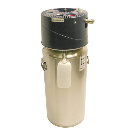
DENT TO THE PROVIDER AND/OR THE MANUFAC- Intended Use TURER. A SERIOUS INCIDENT IS DEFINED AS AN The CAIRE Liberator Oxygen unit is intended for INJURY, DEATH, OR POTENTIAL TO CAUSE INJURY/ the administration of supplemental oxygen. The DEATH SHOULD THERE BE A REOCCURRENCE OF device is not intended for life support nor does it THE INCIDENT. - Page 5 Liberator Introduction Controls 1. Gen 4 Meter Liquid Level Gauge The Liberator reservoir is intended for the adminis- tration of supplemental oxygen to the patient in the 2. Flow Control Knob end user’s home and can also be used in institutions 3.
-
Page 6: Basic Operations
Liberator Caution: Should there be any liquid Operating Instructions leakage from the portable after separat- ing the units, set the portable aside, 1. To verify the level of liquid oxygen in the unit, ensuring it remains vertical, leave the see page 9. room, and call your health care provider immediately. - Page 7 Liberator 2. Use the following chart as a guideline to the recommended tubing length. FLOW MAXIMUM (RECOMMENDED) SETTING TUBING LENGTH* (LPM) 20-psig 50-psig 100 Ft. (30.5 m) 100 Ft. (30.5 m) 100 Ft. (30.5 m) 75 Ft. (22.9 m) 50 Ft. (15.2 m) 50 Ft.
-
Page 8: Battery Care And Maintenance
Liberator Battery Care and Maintenance • Depress button to display level. If level is displayed and Low Battery Indicator is not il- luminated, battery level is acceptable. Humidifier Bottle and Cannula are not included 8. Adjust your breathing cannula to the proper posi- tion to breathe comfortably. -
Page 9: Troubleshooting
Liberator Troubleshooting Issue Solution Inadequate Flow • Verify flow control knob is on correct flow rate setting • Verify flow control knob is not set in between flow rates. • Verify liquid oxygen is in unit • Verify if cannula is kinked or pinched •... -
Page 10: Weee And Rohs
A firebreak is recommended for use with any can- nula. Transport and Storage • CAIRE offers a firebreak intended to be used in conjunction with the oxygen reservoir. The firebreak The device should be stored in the upright position, is a thermal fuse to stop the flow of gas in the event and be well ventilated. -
Page 11: Guidance And Manufacturer's Declaration - Electromagnetic Emissions
Liberator Safety WARNING: PORTABLE RF COMMUNICATIONS EQUIPMENT (INCLUDING PERIPHERALS SUCH AS ANTENNA CABLES AND EXTERNAL ANTENNAS) SHOULD BE USED NO CLOSER THAN 30 CM (12 INCHES) TO ANY PART OF THE LIBERATOR, INCLUDING CABLES SPECIFIED BY THE MANU- FACTURER. OTHERWISE, DEGRADATION OF THE PERFORMANCE OF THIS EQUIPMENT COULD RESULT. -
Page 12: Guidance And Manufacturer's Declaration - Electromagnetic Immunity
Liberator Table 2* Recommended separation distances between portable and mobile RF communications equipment and the Liberator The Liberator is intended for use in an electromagnetic environment in which radiated RF disturbances are controlled. The customer or the user of the Liberator can help prevent electromagnetic interfer- ence by maintaining a minimum distance between portable and mobile RF communications equipment (transmitters) and the Liberator as recommended below, according to the maximum output power of the communications equipment. - Page 13 Liberator Table 4 Guidance and Manufacturer’s Declaration—Immunity ME Equipment and ME Systems Guidance and Manufacturer’s Declaration—Immunity The Liberator is intended for use in the electromagnetic environment specified below. The customer or user of the Liberator should ensure that it is used in such an environment. Immunity Test IEC 60601 Test Level Compliance Level...
- Page 14 Liberator Notes 14 - ENG PN MN234 G | User Manual...
- Page 15 Liberator Notes PN MN234 G | User Manual 15 - ENG...
- Page 16 Brasil 06730-00 Tel/Fax: (55)(11)5535-0989 Email: medstar@medstar.com.br CAIRE and CAIRE Inc. are registered trademarks of CAIRE Inc. Please visit our website below for a full listing of trademarks. Trademarks: www.caireinc.com/ corporate/trademarks/. © Copyright 2020 CAIRE Inc. All Rights Reserved. CAIRE Inc. reserves the right to discontinue its products, or change the prices, materials, equipment, quality, |MN234-GÌ~...
Need help?
Do you have a question about the Liberator 20 and is the answer not in the manual?
Questions and answers