
Related Manuals for Ecoflam Multicalor 170.1


Summary of Contents for Ecoflam Multicalor 170.1
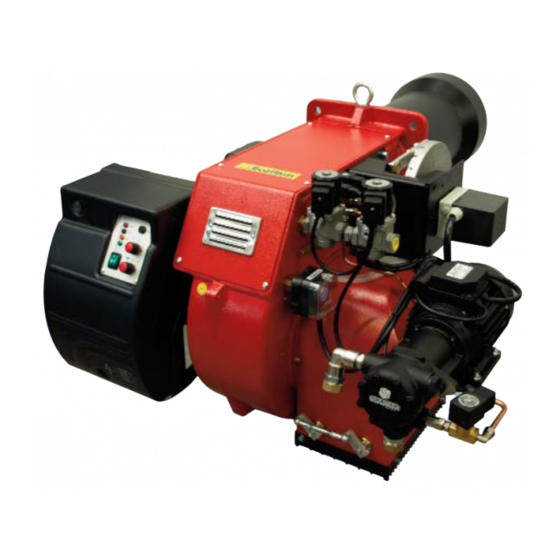
- Page 1 A BRUCIATORI MISTI GAS + GASOLIO B GAS/LIGHT-OIL DUAL BURNERS MODELS Multicalor 170.1 Multicalor 200.1 PR/MD 230/400 V 50 Hz LB 1377 05.07.2004...
-
Page 2: Campo Di Lavoro
A LB 1377 MULTICALOR 170.1 -200.1 PR / MD CARATTERISTICHE TECNICHE Modello : Multicalor 170.1 200.1 Potenza termica max. 1770 2150 kcal/h 1.526.000 1.853.450 Potenza termica min. kcal/h 295.000 356.900 Max. portata gas metano Min. portata gas metano Pressione gas... -
Page 3: Allacciamento Elettrico
LB 1377 MULTICALOR 170.1 -200.1 PR / MD ALLACCIAMENTO ELETTRICO Tutti i bruciatori sono collaudati a 400 V 50 Hz trifase per i motori e 230V 50 Hz monofase con neutro per gli ausilia- ri. Se fosse necessario alimentare il bruciatore a 230 V 50 Hz trifase senza neutro, eseguire le modifiche necessarie rife- rendosi allo specifico schema elettrico del bruciatore e controllare che il relé... - Page 4 A LB 1377 MULTICALOR 170.1 -200.1 PR / MD FUNZIONAMENTO APPARECCHIATURA LANDIS LGB 22 L’apparecchiatura Ciclo di funzionamento in mancanza Ciclo di funzionamento normale controllo fiamma di fiamma all'accensione fa partire il venti- Pressostato gas latore del brucia- Motore ventilatore...
- Page 5 LB 1377 MULTICALOR 170.1 -200.1 PR / MD N.B.) - La pressione misurata alla presa E deve rientrare nel campo di lavoro del pressostato. Se ciònon fosse. allen- tare il dado di bloccaggio alla base della vite F ed agire gradualmente sulla stessa; in senso orario per diminuire la pressione, antiorario per aumentarla.
- Page 6 A LB 1377 MULTICALOR 170.1 -200.1 PR / MD REGOLAZIONE DELLA PORTATA MASSIMA DELL’ARIA Svitare la vite di fissaggio dell’asta e mettere la stessa nella posizione corretta. Alla fine della regolazione richiudere la vite dell’asta. REGOLAZIONE DELLA PORTATA INTERMEDIA DEL GAS Azionare il servomotore con il commutatore (aperto/chiuso) e posizionarlo nella posizione 0 per fermarlo.
-
Page 7: Alimentazione Combustibile
LB 1377 MULTICALOR 170.1 -200.1 PR / MD AVVIAMENTO DEL BRUCIATORE GASOLIO Dopo aver eseguito l’installazione del bruciatore, verificare i seguenti punti: - Tensione di alimentazione del bruciatore ed i fusibili di protezione di rete. - I collegamenti del motore. - Page 8 A LB 1377 MULTICALOR 170.1 -200.1 PR / MD CIRCUITO IDRAULICO GASOLIO A - FLESSIBILI B - FILTRO C - RUBINETTO 1 - POMPA ASPIRAZIONE 2 - VALVOLA GASOLIO DI SICUREZZA 3 - VALVOLA GASOLIO RITORNO 4 - UGELLO 5 - PRESSOSTATO GAS...
- Page 9 LB 1377 MULTICALOR 170.1 -200.1 PR / MD UGELLI FLUIDICS pag.9...
-
Page 10: Posizione Elettrodi
A LB 1377 MULTICALOR 170.1 -200.1 PR / MD POSIZIONE ELETTRODI 3 ÷ 4 mm 5 ÷ 6 mm PULIZIA E SOSTITUZIONE DELL’UGELLO Utilizzare solo la apposita chiave fornita in dotazione pre rimuovere l’ugello, facendo attenzione a non danneggiare gli elettrodi. Montare il nuovo ugello con la medesima cura. - Page 11 LB 1377 MULTICALOR 170.1 -200.1 PR / MD CONTROLLO ANNUALE Il controllo periodico del bruciatore (testa di combustione, elettrodi,ecc.) deve essere effettuato da personale autorizzato una o due volte all’anno a secondo dell’utilizzo. Prima di procedere al controllo per la manutenzione del bruciatore è...
- Page 12 A LB 1377 MULTICALOR 170.1 -200.1 PR / MD REGOLATORE A MICROPROCESSORE RWF 40 Significato del display e dei tasti del regolatore a microprocessore RWF 40 Nella figura viene visualizzato il display di base, Display: che indica il valore reale ed il setpoint ingresso analogico impostato, é...
- Page 13 LB 1377 MULTICALOR 170.1 -200.1 PR / MD IMPOSTAZIONI PARAMETRI All’accensione del bruciatore tutti i dislay del regolatore sono accesi, il display del setpoint lampeggerà per circa 10 sec. Il valore visualizzato nel dislay superiore (rosso) indica il valore reale. Il valore visualizzato nel dislay inferiore (verde) indica il valore del set- point impostato.
- Page 14 A LB 1377 MULTICALOR 170.1 -200.1 PR / MD PARAMETRIZZAZIONE 17.5 12.5 -2.5 -7.5 -12.5 -17.5 Temperatura esterna (¡C) SCHEMI COLLEGAMENTO SONDE Collegamento sonda Cod. S721 Cod. RWF 40 Cod. QAE2..(sonda passiva) S720/1 S731 Sonda acqua S731/1 Codice configurazione S731/2...
- Page 15 LB 1377 MULTICALOR 170.1 -200.1 PR / MD INDICAZIONI CONFIGURAZIONE INGRESSI C111 - C112 Ingresso analogico 1 (valore reale) Ingresso analogico 3 (temperatura esterna) Pt1000, 2 fili, Landis & Staefa IEC 751 Nessuna funzione (sonda non attiva) FT-TP/...(sonda passiva) Sonda esterna Pt 1000, 2 fili, Ni1000, 2 fili, Landis &...
- Page 16 A LB 1377 MULTICALOR 170.1 -200.1 PR / MD NEL CASO DI NECESSITÀ DI SOSTITUZIONE PROCEDERE COME INDICATO NELLE SOTTOSTANTI FIGURE A-B-C Inserire il regolatore RWF 40 nell’apposita apertura del cassetto elettrico (A). Inserire nelle fessure i tasselli ad incastro con le viti, quindi bloccarla al pannello della cassetta per una corretta tenuta (B).
- Page 17 LB 1377 MULTICALOR 170.1 -200.1 PR / MD IMPOSTAZIONI PARAMETRI Parametro Display Valore impostato Valore impostato Valore impostato (sonda passiva) (sonda passiva) (sonda attiva) QAE22 FT-TP/1000 QBE620-P... Valore limite del contatto ausiliario Differenziale di commutazione del contatto ausiliario HYSt Banda proporzionale Pb.1...
-
Page 18: Working Fields
B LB 1377 MULTICALOR 170.1 -200.1 PR / MD TECHNICAL DATA Models : Multicalor 170.1 200.1 Thermal power max. 1770 2150 kcal/h 1.526.000 1.853.450 Thermal power min. kcal/h 295.000 356.900 Max. capacity (Natural gas) Min. capacity (Natural gas) Gas pressure (LPG) mbar Max. -
Page 19: Electrical Connections
LB 1377 MULTICALOR 170.1 -200.1 PR / MD ELECTRICAL CONNECTIONS All burners are factory tested and set at 400 V 50 Hz three-phase for motors and 230 V 50 Hz monophase with neutral for auxiliaries. If it is necessary to supply the burner at 230 V 50 Hz without neutral,make the necessary alterations referring to the wiring diagram of the burner and check that the termal relay is within the absorption range of the motor. -
Page 20: Gas Circuit
B LB 1377 MULTICALOR 170.1 -200.1 PR / MD LANDIS LGB 22 UP-CYCLE The control box starts the Normal operative cycle ignition Operative cycle with flameless burner fan, to carry out the prepurging of the com- Gas pressure switch bustion chamber, and... -
Page 21: Air Adjustment
LB 1377 MULTICALOR 170.1 -200.1 PR / MD LANDIS & STAEFA SQN 31 251A2700 AIR DAMPER MOTOR Remove cover to gain access to the adjusting cams.The cams are to be adju- sted through the suitable key provided for. Description: - Limit switch for air damper “High Flame” position adjustment (Max. -
Page 22: Adjusting The Intermediate Burner Capacity
B LB 1377 MULTICALOR 170.1 -200.1 PR / MD ADJUSTING THE INTERMEDIATE BURNER CAPACITY Using the selector, start the servomotor (closing or opening) and position on 0 to stop the stroke; the adjustment is made as outlined below. Repeat the operation for the other cam points. - Page 23 LB 1377 MULTICALOR 170.1 -200.1 PR / MD WORKING OF THE BURNER WITH LIGHT-OIL FUEL Once having installed the burner, check the following items: - The burner power feeding and the main line protection fuses - The correct length of pipes and that the same are sealed.
- Page 24 B LB 1377 MULTICALOR 170.1 -200.1 PR / MD LIGHT-OIL CIRCUIT A - HOSE B - OIL FILTER C - OIL COCK 1 - PUMP SUCTION ASPIRAZIONE 2 - SAFETY OIL VALVE 3 - OIL VALVE RETURN RITORNO 4 - NOZZLE...
- Page 25 LB 1377 MULTICALOR 170.1 -200.1 PR / MD UGELLI FLUIDICS pag.25...
-
Page 26: Description Of Control Panel
B LB 1377 MULTICALOR 170.1 -200.1 PR / MD POSITION OF IGNITION ELECTRODES 3 ÷ 4 mm 5 ÷ 6 mm NOZZLE CLEANING AND REPLACEMENT Use only the suitable box wrench provided for this operation to remo- ve the nozzle, taking care to not damage the electrodes. Fit the new nozzle with the same care. -
Page 27: Maintenance
LB 1377 MULTICALOR 170.1 -200.1 PR / MD MAINTENANCE YEARLY CONTROLS The periodical check of the burner (firing head, electrodes etc.) must be carried out one or two times a year, by authorised person- nel only. Before proceeding with the controls for the maintenance, it should be advisable to check the general status of the burner as follows: - Disconnect the burner from the power supply - Turn off the gas cut-off cock - Remove the burner’s cover and clean... - Page 28 B LB 1377 MULTICALOR 170.1 -200.1 PR / MD RWF 40 MICROPROCESSOR REGULATOR Description of display and keys on the RWF 40 microprocessor regulator The figure shows the normal display indicating Display: the actual value and the programmed set analog input 1...
-
Page 29: Setting Parameters
LB 1377 MULTICALOR 170.1 -200.1 PR / MD SETTING PARAMETERS When the burner is ignited all displays of the regulator light up. The set point display will blink for about 10 seconds. The value in the upper field of the display (red) indicates the actual value. The value in the lower field of the display (green) indicates the set point currently programmed. - Page 30 B LB 1377 MULTICALOR 170.1 -200.1 PR / MD PARAMETERIZATION 17.5 12.5 -2.5 -7.5 -12.5 -17.5 External temperature (iC) PROBE CONNECTION DIAGRAMS Connection for probe Cod. S721 Cod. RWF 40 Cod. QAE2..(passive probe) S720/1 S731 Water probe S731/1 Configuration code...
- Page 31 LB 1377 MULTICALOR 170.1 -200.1 PR / MD C111 – C112 INPUT CONFIGURATION INDICATIONS Analog input 1 (actual value) Analog Input 3 (external temperature) Pt1000, 2-wire, Landis & Staefa IEC 751 No function (probe not active) FT-TP/… (passive probe) External probe Pt 1000, 2-wire, QAC22 (passive probe) Ni1000, 2-wire, Landis &...
- Page 32 B LB 1377 MULTICALOR 170.1 -200.1 PR / MD WHEN REPLACEMENT IS NECESSARY, PROCEED AS SHOWN IN FIGURES A-B-C BELOW Insert the RWF 40 regulator through the relative opening in the electrical panel (A). Insert the fixing anchors and screws into the slots, and secure the unit to the panel (B).
- Page 33 LB 1377 MULTICALOR 170.1 -200.1 PR / MD PARAMETERS Parameter Display Ecoflam setting Ecoflam setting Ecoflam setting (passive probe) (passive probe) (active probe) QAE22 FT-TP/1000 QBE620-P... Limit value of limit comparator Switching differential for limit comparator HYSt Proportional band Pb.1...
- Page 34 AB LB 1377 MULTICALOR 170.1 -200.1 PR / MD pag.34...
- Page 35 LB 1377 MULTICALOR 170.1 -200.1 PR / MD AB N° DESCRIZIONE Multicalor 170.1 Multicalor 200.1 PR/MD PR/MD codice codice - PRESSOSTATO ARIA DUNGS LGW10 A2P Q120 Q120 - GRUPPO PRESE ARIA GRPA100 GRPA100 - SPINA WIELAND 6 pin E226 E226...
- Page 36 B LB 1377 MULTICALOR 170.1 -200.1 PR / MD N° DESCRIPTION Multicalor 170.1 Multicalor 200.1 PR/MD PR/MD code code - AIR PRESSURE SWITCH DUNGS LGW10 A2P Q120 Q120 - AIR INTAKE SET GRPA100 GRPA100 - WIELAND PLUG 6 pin E226...
- Page 37 LB 1377 MULTICALOR 170.1 -200.1 PR / MD AB pag.37...
- Page 38 AB LB 1377 MULTICALOR 170.1 -200.1 PR / MD INTERRUTTORE GENERALE CON FUSIBILE INTERRUTTORE DI LINEA MAIN SWITCH WITH FUSE WORKING SWITCH INTERRUPTEUR GENERAL AVEC FUSIBLE INTERRUPTEUR DE LIGNE INTERRUPTOR GENERAL CON FUSIBLE INTERRUPTOR DE LINEA FILTRO ANTIDISTURBO FILTRO ANTIDISTURBO...
- Page 39 LB 1377 MULTICALOR 170.1 -200.1 PR / MD AB pag.39...
- Page 40 Ecoflam S.p.A. via Roma, 64 - 31023 RESANA (TV) - Italy - tel. 0423/715345 r.a. telefax 0423-715444 (Italy 480009 - Export 480873, 715538). http://www.ecoflam.it - e-mail: ecoflam@ecoflam.it...
Need help?
Do you have a question about the Multicalor 170.1 and is the answer not in the manual?
Questions and answers