Table of Contents
Advertisement
Quick Links
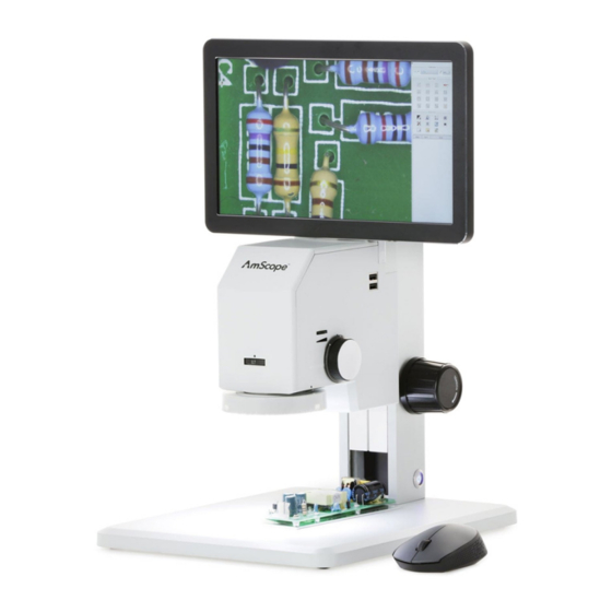
DM745-HDM11 Digital-Integrated Microscope
Introduction
This manual applies to the DM745-HDM11 digital-integrated microscope and accessories. The information in this manual
is provided to help you familiarize yourself with the assembly and use of the products. Please read thoroughly before
using the products, and keep this manual with the product for reference.
v0.9.20220708
Advertisement
Table of Contents

Related Manuals for AmScope DM745-HDM11


Summary of Contents for AmScope DM745-HDM11
- Page 1 DM745-HDM11 Digital-Integrated Microscope Introduction This manual applies to the DM745-HDM11 digital-integrated microscope and accessories. The information in this manual is provided to help you familiarize yourself with the assembly and use of the products. Please read thoroughly before using the products, and keep this manual with the product for reference.
- Page 2 Other indicators can be a loud buzzing sound or crackling. Contact AmScope to report such behavior. Do not use around flammable liquids or gases. Electric instruments can ignite flammable substances which could result in an explosion or fire.
-
Page 3: Table Of Contents
Contents Specifications ................................4 What’s In The Box ..............................5 Assembly ................................6 Attaching the Monitor ................................ 6 USB Devices..................................7 Wireless Mouse ........................................7 Storage Devices ........................................7 Attaching the 3D Attachment ............................. 8 Operation ................................9 Focusing ..................................... 9 Magnification .................................. - Page 4 D M 7 4 5 - H D M 1 1 Us e r Gu ide Page 4...
-
Page 5: Specifications
Displayed Magnification 11.3X-72.5X Native Resolution 1920 x 1080 Aspect Ratio 16:9 Brightness 220 nits What’s In The Box The DM745-HDM11 standard outfit includes: • One microscope with track stand • One monitor • Three thumb screws • One USB wireless mouse •... -
Page 6: Assembly
D M 7 4 5 - H D M 1 1 Us e r Gu ide Assembly Attaching the Monitor Tilt the mounting bracket back 90 degrees so it is pointing up. Place the monitor in front of the bracket with the screen facing the front of the microscope. -
Page 7: Usb Devices
D M 7 4 5 - H D M 1 1 Us e r Gu ide USB Devices The microscope has two USB ports on its right side. These can be used to attach USB devices such as the included mouse, a keyboard, and storage devices. -
Page 8: Attaching The 3D Attachment
D M 7 4 5 - H D M 1 1 Us e r Gu ide Attaching the 3D Attachment The optional 3D attachment is designed to mount to the objective lens’ housing. The 3D attachment’s mounting ring has female threads which will screw onto the objective housing’s male threads. Guide the 3D attachment’s mounting ring upward onto the objective housing, then rotate to the right using the knurled portion of the ring. -
Page 9: Operation
D M 7 4 5 - H D M 1 1 Us e r Gu ide Operation Focusing Each side of the microscope’s focusing column is equipped with a focusing knob. Rotating either knob will raise or lower the microscope’s head. Tension can be adjusted for the knobs by securing one in place, then rotating the other. -
Page 10: Optical Magnification
D M 7 4 5 - H D M 1 1 Us e r Gu ide Optical Magnification This microscope uses a combination of a fixed-magnification 1X objective lens and zoom optics to provide its 0.7X-4.5X magnification range. This is the optical magnification range which is typically listed. An additional 0.35X magnification stage is used to compensate for the format of the digital image sensor. -
Page 11: Illumination
D M 7 4 5 - H D M 1 1 Us e r Gu ide Illumination This microscope is equipped with an LED ring light to provide illumination. The ring light can be removed to expose the objective lens housing by simultaneously pulling downward on the left and right sides. When reattaching, be sure to align the two electrical contact on the top of the ring light with the pins on the underside of the microscope head. -
Page 12: Software
D M 7 4 5 - H D M 1 1 Us e r Gu ide Software The DM745-HDM11 uses internal software to manage camera and display settings, as well as to perform image-capture and measuring functions. All of these functions are accessed from the on-screen console. The console is divided into four sections including Calibration, Main Tools, Assist Tools, and a measurements log. -
Page 13: Calibration
D M 7 4 5 - H D M 1 1 Us e r Gu ide Calibration The calibration section is used to select precalibrated magnification profiles or to define custom profiles. A magnification profile defines the relationship between camera pixels and real units of measure such as millimeters. Once this relation- ship is defined, any shape drawn on the screen will provide accurate measurements by translating the number of pixels into the desired unit of measure. -
Page 14: Main Tools
D M 7 4 5 - H D M 1 1 Us e r Gu ide Main Tools The Main Tools section contains measuring tools, reticles, and a text tool. These tools allow you to draw shapes to mea- sure distances or areas. Panel Function Description... -
Page 15: Assist Tools
D M 7 4 5 - H D M 1 1 Us e r Gu ide Assist Tools The Assist Tools section provides the tools necessary for managing system settings, capturing images, and exporting files. Panel Function Description Edge Detect Mode: select from automatic and manual Graphics Settings: change characteristics of shapes including color Output Settings... -
Page 16: The Camera Settings Panel
D M 7 4 5 - H D M 1 1 Us e r Gu ide The Camera Settings Panel The Camera Settings panel provides controls for manipulating camera settings which can optimize image quality for spe- cific subjects. Panel Function Description Adjust the brightness of the image. -
Page 17: Image Exposure
D M 7 4 5 - H D M 1 1 Us e r Gu ide Image Exposure Manual Exposure The brightness setting is used to manually control the amount of light captured by the imaging device. Manual control is preferable when imaging light or dark specimens which do not appear properly exposed when using auto exposure. -
Page 18: System Settings
D M 7 4 5 - H D M 1 1 Us e r Gu ide System Settings The System Settings panel allows you to customize general software settings. Page 18... -
Page 19: General Settings
D M 7 4 5 - H D M 1 1 Us e r Gu ide General Settings Cursor Type You can select either of two options for the type of cursor to display, including the arrow and the crosshair. Menu Position The main menu console can be docked on the left or right side. -
Page 20: Image Tab
D M 7 4 5 - H D M 1 1 Us e r Gu ide Image Tab Image Data Source This selects what will be included in saved images. Video includes the image generated by the camera. Scene includes any reticle, graphics or text overlaying the image. -
Page 21: File Tab
D M 7 4 5 - H D M 1 1 Us e r Gu ide File Tab File Naming Method Select manual to be prompted for a file name when saving an image, or auto to generate a name automatically. File Naming Length This sets the number of digits to be used when using the “serial number”... -
Page 22: Folder Tab
D M 7 4 5 - H D M 1 1 Us e r Gu ide Folder Tab Folder Naming Length This sets the number of digits to be used when using the “serial number” option with automatically generated file names. -
Page 23: Misc Tab
D M 7 4 5 - H D M 1 1 Us e r Gu ide Misc Tab Open scale bar This will display a scale bar on the bottom of the screen. Open small view Not currently used. Pop-up window after calibration is complete By default, you would need to right-click on the screen after drawing a reference line during the calibration process to display the calibration pop-up window.
Need help?
Do you have a question about the DM745-HDM11 and is the answer not in the manual?
Questions and answers