Table of Contents
Advertisement
Advertisement
Table of Contents

Related Manuals for AmScope MU USB3.0


Summary of Contents for AmScope MU USB3.0
- Page 1 MU Camera Series User’s Manual (Windows)
-
Page 2: Table Of Contents
Before Use ......................5 Introduction ........................5 Safety Precautions ......................6 Parts ........................7 MU USB2.0 Camera ......................7 MU USB3.0 Camera ......................8 Definition of Parts .......................9 Definition of Parts (Continued) ..................10 Getting Started ....................11 Quick Start ........................11 Installing the Software (CD) ....................12 Installing the Software (Download) ..................17... - Page 3 Image Enhancement Tools ....................50 Top Navigation Bar ................... 51 File Menu ..........................51 Edit Menu .........................53 View Menu ........................54 Browse Menu ........................56 Setup Menu ........................57 Capture Menu ........................58 Image Menu ........................59 Process Menu ........................60 Layer Menu ........................63 Measurement Menu ......................64 Options Menu ........................65 Window Menu ........................66 Help Menu ........................67 Process Menu Tools ..................
- Page 4 Auto Correction Menu ....................143 Window Menu Functions ................144 Window Menu ........................144 Troubleshooting ..................... 145 Common Issues .......................145 User’s Manual MU Series (Windows)
-
Page 5: Before Use
This document, the information in this document and all rights thereto are the sole and exclusive prop- erty of AmScope and are not to be copied, used or disclosed to anyone, in whole or in part, without the express written permission of AmScope. -
Page 6: Safety Precautions
Before Use Safety Precautions 1. As the microscope camera is a precision instrument, always handle it with care, avoiding impact or abrupt movement during transporation. Do not shake the package. 2. Do not place the microscope camera in direct sunlight or in high heat. Keap it indoors in a dry and clean place with temperateures between 32-100 degrees F (0-40 degrees C), and in maximum relative humidity of 85%. -
Page 7: Parts
Parts MU USB2.0 Camera USB Cable Camera Body Adapter Sleeves Reduction Lens (SKU: RU050) User’s Manual MU Series (Windows) -
Page 8: Mu Usb3.0 Camera
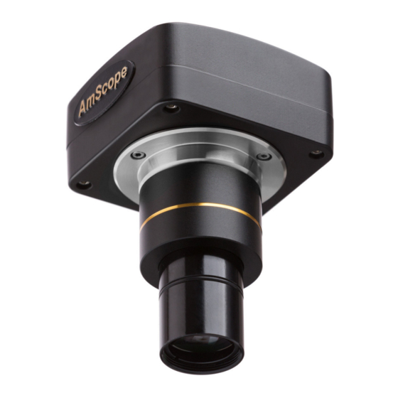
Parts MU USB3.0 Camera USB Cable Camera Body Reduction Lens (SKU: RU050) Adapter Sleeves USB Port (3.0 is Blue, 2.0 is White) User’s Manual MU Series (Windows) -
Page 9: Definition Of Parts
Parts Definition of Parts Adapters/Spacers Metal cylindrical sleeves that adapt a larger size ocular tube down to 23.2mm for the camera to fit. Camera Body Square metallic housing that holds the camera sensor and circuit board, as well as has a port to con- nect a USB cable. -
Page 10: Definition Of Parts (Continued)
A lens that both reduces the incoming magnification from the microscope to better fit the image to the sensor’s size in the camera, and adapts the C-mount connection down to a 23.2mm port size, common on AmScope microscope models. Software CD CD that includes a copy of the software and driver for the camera, which allows the Windows PC to both inter- face with the camera, and allows the user to interact with the camera via the on screen controls. -
Page 11: Getting Started
Getting Started Quick Start 1. Check the packing list on www.amscope.com or included in your package to ensure that you’re received all items that are to be included: - 1 Camera Body (SKU on sticker) (USB2.0 or USB3.0) - 1 Reduction Lens/Adapter - 1 Camera Adapter (30mm to 23.2mm) -
Page 12: Installing The Software (Cd)
1. Begin by placing the software CD in your computer’s CD tray, and insert the CD. 2. Windows should either bring up the AutoPlay function. When asked, select the first option “Run autorun. exe” in order to access the AmScope/ToupView installation menu. 3. Next, click “Install Application” to start the Installation Wizard. - Page 13 Getting Started Installing the Software (CD) (Continued) 4. Once the Installation Wizard has opened, please click “Next” to continue. User’s Manual MU Series (Windows)
- Page 14 Getting Started Installing the Software (CD) (Continued) 5. The next window will let you choose where you wish to install the program to. If unsure, leave as default, and press “Install” to continue. Pressing “Browse” will allow you to navigate to the folder you wish to install the software to using the File Browser, or, if known, you may type in the address to the Destination Folder directly.
- Page 15 Getting Started Installing the Software (CD) (Continued) 6. The Installation Wizard will then begin installing the program onto your computer’s hard drive in the folder designated by you on the previous page. Please wait until the bar has been completely filled, upon which the Installation Wizard will automatically prog- ress to the final Installation Wizard window.
- Page 16 By keeping the “Run AmScope 3.7” box ticked, upon hitting “Finish,” the software will open. If unticked, pressing “Finish” will simply close the Installation Wizard.
-
Page 17: Installing The Software (Download)
2. Open your web browser (Google Chrome, Internet Explorer/Edge, Mozilla, Safari, Opera, etc), and in the ad- dress bar, type “www.amscope.com/software-download”, and press Enter. Note: Alternatively, you may input “www.amscope.com” and navigate to the bottom of the page to find a section titled “Customer Support,” and click “Camera Software Downloads” to open the page. - Page 18 Getting Started Installing the Software (Download) (Continued) 4. To the right of the “Select Camera” drop down menu, there is a second drop down menu titled “Select Oper- ating System.” Click the arrow to drop the menu down, and select “Windows” by clicking on it. Note: If you’d rather manually search for the software/driver, you can also simply scroll down the page until you find “MU Series”...
- Page 19 Getting Started Installing the Software (Download) (Continued) 6. By clicking “download,” your web browser will automatically begin downloading the installer package to the location that is set as your Downloads folder. Some web browsers will show the download on the bottom of the bar once completed, or will appear in a “Downloads List”...
- Page 20 Getting Started Installing the Software (Download) (Continued) 9. The installer file is packaged in a .zip file, which is a compressed file format that allows you to send multiple files over the internet as a single file, and compresses them so that the file size is smaller, and thus, faster/easi- er to transfer.
- Page 21 Getting Started Installing the Software (Download) (Continued) 11. Look for the installer file, which has a file extension (ending) of .exe, and a type of Application. Double click this in order to run the Installation Wizard. 12. When the Installation Wizard window opens up, please click “Next” to proceed. User’s Manual MU Series (Windows)
- Page 22 Getting Started Installing the Software (Download) (Continued) 13. The second page of the Installation Wizard lists the software license terms and conditions of use. Please read through them and click “I Agree” when complete to proceed. If you do not agree with the license terms, the software cannot be installed and used.
- Page 23 Getting Started Installing the Software (Download) (Continued) 14. Now, you will be given an option to select a location to install the software to. You can leave this at the default location if unsure or you do not have a preference, or, press “Browse” to select a folder to install the program to.
- Page 24 “Finish” button. The driver still must be installed before the camera will function, so untick the “Run AmScope” box, and click “Finish.” 16. Navigate back to the folder to which the driver download is located. We offer two drivers (DirectShow and Twain), however, DirectShow works with most applications for most users.
- Page 25 Getting Started Installing the Software (Download) (Continued) 17. When the Installation Wizard window opens up, please click “Next” to proceed. User’s Manual MU Series (Windows)
- Page 26 Getting Started Installing the Software (Download) (Continued) 18. The second page of the Installation Wizard lists the software license terms and conditions of use. Please read through them and click “I Agree” when complete to proceed. If you do not agree with the license terms, the driver cannot be installed and used.
- Page 27 Getting Started Installing the Software (Download) (Continued) 19. Now, you will be given an option to select a location to install the driver to. You can leave this at the default location if unsure or you do not have a preference, or, press “Browse” to select a folder to install the program to.
- Page 28 Getting Started Installing the Software (Download) (Continued) 20. The Installation Wizard will proceed to install the DirectShow or Twain driver. When it has completed, it will automatically move to the final page. User’s Manual MU Series (Windows)
- Page 29 22. You are now ready to open the software and use the camera. Please plug in the camera, and navigate to your desktop. You will now see either a yellow “A” or a yellow “T” (AmScope / ToupView) depending on what version of the software you chose to install.
-
Page 30: Using The Software
Using the Software Activating the Camera 1. Begin by opening the software. Double click your AmScope/ToupView shortcut icon (the yellow “A” or “T”) from the desktop, or single click the AmScope/ToupView shortcut icon from the start menu. 2. Once loaded, locate the “Device List” on the left hand navigation bar, and click the camera name to activate the live view from the camera. -
Page 31: Capturing & Saving A Still Image
Using the Software Capturing & Saving a Still Image 1. To capture an image, once you are focused on the sample and it is in clear view in the software view, simply press the “Snap” button with the photo of the camera. Be sure to set the “Snap” resolution to the resolution desired of the still image recording prior to pressing “Snap.”... -
Page 32: Recording & Saving A Video
Using the Software Recording & Saving a Video 1. To record a video, once you are focused on the sample and it is in clear view in the software view, simply press the “Record” button with the photo of the “Play” button (the triangle pointing to the right). Be sure to set the “Snap”... - Page 33 Using the Software Recording & Saving a Video 3. The “Video Format and Encoder” menu will appear next, asking which file format you would like to save and encode your video in. Most users will use .wmv or .avi. If unsure, use .wmv, and press “Next.” User’s Manual MU Series (Windows)
- Page 34 Using the Software Recording & Saving a Video (Continued) 4. The “Encoder” menu will appear next, asking what parameters you would like to use to encode your video, such as what bitrate you would like to use, the quality, and the key frame spacing. If unsure, leave these at de- fault.
- Page 35 Using the Software Recording & Saving a Video (Continued) 5. The “Display Information” menu will appear next, allowing you to set the ID3 tags for your video. These are file properties that will show up in certain playback softwares, and is useful for cataloging results. While not neces- sary, you may fill in this section.
- Page 36 Using the Software Recording & Saving a Video (Continued) 6. The “Start to Record” menu will appear next, allowing you to set how long you wish the video to record for (if you wish to set a limit), and the time-lapse (time between captured frames). These can be adjusted if desired, or left alone to have a normal, smooth video that will record until you hit the “Record”...
- Page 37 We recommend Video Lan Controller (VLC), which is a free to use software available on the internet, and has a wide compatibility with different codecs and encoding methods. Note: We at AmScope are not affiliated with VLC in any way, shape, or form. User’s Manual...
-
Page 38: Left Hand Navigation Bar (Camera Bar)
Using the Software Understanding the Software Options This section covers the various options and adjustments that the software is capable of. Understanding these software options is essential to successful operation of the software, and in getting the desired results. Every camera sensor is a little different, even from the same assembly line, and every environment and sample has differences, thus, the options here are designed to allow you the flexibility to compensate for those factors. -
Page 39: Camera List
Left Hand Navigation Bar (Camera Bar) Camera List This section displays the connected device(s) to your system. Note that only one camera will be recognized at a time by the software, usually whichever is the most recently attached device. Clicking a camera in this section will activate that camera in the viewing area to the right of the navigation bar. Capture &... -
Page 40: Exposure & Gain
Left Hand Navigation Bar (Camera Bar) Exposure & Gain This section contains various settings regarding exposure, which is how much light the camera sensor accepts per frame, and gain, which is a brightness setting controlling how dark “black” colors appear. By default, the “Auto Exposure”... -
Page 41: White Balance
Left Hand Navigation Bar (Camera Bar) White Balance This section allows for adjustments in “Color Temperature” and “Tint” in order to ensure that the camera sen- sor is capturing the correct colors. Often times, cameras can come out of the box seeing different colors differ- ently, and thus displaying them as such. -
Page 42: Color Adjustment
Left Hand Navigation Bar (Camera Bar) Color Adjustment Much like the section before it, this section allows you greater control over the colors as they appear in your image through various sliders. The “Hue” adjustment allows you to shift the colors displayed between the entire visible color spectrum. Ad- just as needed if your colors are entirely shifted the wrong way. -
Page 43: Power Frequency (Anti-Flicker)
Left Hand Navigation Bar (Camera Bar) Power Frequency (Anti-Flicker) This section is only available by turning “Auto Exposure” off in the “Exposure & Gain” section. It allows you to set the CMOS sensor to capture frames in alignment with the frequency of local power supply powering the microscope. -
Page 44: Color/Grey
Left Hand Navigation Bar (Camera Bar) Color/Grey This section allows you to switch the camera sensor between “Color” mode and “Gray” mode. Color captures images in color, while Gray captures images in grayscale (black and white). Flip This section allows you to flip the image received from the camera along either the “Horizontal” or “Vertical” axes. -
Page 45: Bit Depth
Left Hand Navigation Bar (Camera Bar) Bit Depth Bit depth refers to the color information stored in an image. The higher the bit depth, the more colors it can store. 1 bit stores 2 values, so a 16 bit image can store 32 different color values. ROI (Region of Interest) This section allows you to select a specific area in your sample’s view area as the region that one is interested in viewing. -
Page 46: Dark Field Correction
Left Hand Navigation Bar (Camera Bar) Dark Field Correction Darkfield images are a specialized type of microscopy used to create additional contrast in a sample by using a dark background instead of a light background, as well as lighting the sample from oblique angles (lighting the edges of the sample by angled lighting). -
Page 47: Misc
Left Hand Navigation Bar (Camera Bar) Misc This section only contains a single function, “Negative,” which inverts the colors in the image. Parameters This section allows you to save all of the above options as a configuration file, which can be later recalled to avoid having to set them each time. -
Page 48: Top Toolbar
Top Toolbar This section is located above the left navigation bar and viewing area, and contains shortcuts to many tools the software has to further enhance your image, create annotations, or simple quality of life improvements. Each one will be covered in the following sections. File Shortcuts The first four icons on the toolbar (from left to right): Open Image - Open a single image file. -
Page 49: Selection & Movement Tools
Top Toolbar Selection & Movement Tools The following two tools are used to select or highlight an area in an image or video, and if zoomed in, to move the zoomed in area around to scan. From left to right: Select - Allows you to highlight an area of interest in the viewing area. -
Page 50: Calibration Shortcuts
Top Toolbar Calibration Shortcuts The following two tools are used as shortcuts to access calibration menus. From left to right: Calibration - Opens the Calibration menu, allowing you to use a unit of known measurement and a given mag- nification to provide the software with the means to extrapolate real distances from pixels counted on screen. Grey Calibration - Provides the average gray value in the image per frame displayed. -
Page 51: Top Navigation Bar
Top Navigation Bar Above the tool bar is the top navigation bar, which begins with the “File” drop down menu, and ends with the “Help” drop down menu. These menus contain the full range of tools and options that the software is capable of, although since there are many shortcuts on the tool bar and the left hand navigation bar for commonly used procedures, using the menus is generally only as a last resort if a feature you need is not available via a tool or shortcut. - Page 52 Twain: Select Device - AmScope/ToupView software supports other Twain compatible image capture devices. Unfortunately, we at AmScope do not support other devices on our software, nor do we support third party softwares for our camera devices. This menu option is used to select a Twain compatible source to use within the software.
-
Page 53: Edit Menu
Top Navigation Bar Edit Menu The “Edit” menu contains options for manipulating items on the clipboard, and the current active window. Cut - This menu option allows the user to remove a selection from the image attached and place it on the clip- board to be placed somewhere else. -
Page 54: View Menu
Top Navigation Bar View Menu The “View” menu contains options for manipulating the current active view, navigation bars, and opened tabs. Browse - This menu option opens the file explorer box, allowing you to navigate and select an image or video to open from your hard drive. - Page 55 Top Navigation Bar View Menu (Continued) Track - When zoomed in to the image to the point where the image is larger than the display area (or using a high resolution setting to view from the camera), the “Track” or “Hand” tool is used to slide the image to scan different areas.
-
Page 56: Browse Menu
Top Navigation Bar Browse Menu The “Browse” menu is disabled unless a file browsing tab is open in the viewing area. This can be done by click- ing the “Folders” tab in the bottom section of the left navigation bar, then clicking the “Browse” button. Sort - The “Sort”... -
Page 57: Setup Menu
Top Navigation Bar Setup Menu The “Setup” menu is used primarily to adjust settings related to producing video, such as watermarks, file properties, and overlays. Start/Pause - The “Start/Pause” command allows the user to freeze the image provided from the camera or the video being viewed in place. -
Page 58: Capture Menu
Top Navigation Bar Capture Menu The “Capture” menu encompasses tools that are used to take a photo, record a video, or start a broadcast. Capture Image - This function captures a still image, much like the “Snap” button. F8 is the keyboard shortcut for this function. -
Page 59: Image Menu
Top Navigation Bar Image Menu The “Image” menu allows you to process the user’s current active image much like the selection modification in the “Edit” menu, with tools such as rotation, adjustment levels, cropping, scaling, and more. Mode - This menu option encompasses three camera mode options: “Color Quantize,” “Grey Scale,” and “Con- trast Preserving Decoloratization.”... -
Page 60: Process Menu
Top Navigation Bar Process Menu The “Process” menu contains a plethora of useful tools to create more deeply focused, larger viewable area, and better annotated images using digital enhancement procedures built right into the software. Stitch... - The Stitch tool allows users to take images taken at different points along the X and Y axes, and put them together into a single image. - Page 61 Top Navigation Bar Process Menu (Continued) Color Composite - The “Color Composite” tool allows the user to select various color channels, and separate them into independently controlled elements. This allows a user to isolate specific colors of interest and elimi- nate others--particularly useful in fluorescent microscopy.
- Page 62 Top Navigation Bar Process Menu (Continued) Range - The “Range” function allows the user to set a high and low limit for color intensity, allowing one to increase contrast, specifically in low light situations. The “Range” function will be covered in a later section. Binary - The “Binary”...
-
Page 63: Layer Menu
Top Navigation Bar Layer Menu The “Layer” menu is used to create and manipulate various different levels within the image. Each layer can contain image data, measurement data, or other annotations, allowing a user to non-destructively create these notes on an image, and edit or delete one, without having to start over again, or take a new image if a change needs to be made. -
Page 64: Measurement Menu
Top Navigation Bar Measurement Menu The “Measurement” menu contains the same tools as the top toolbar for drawing and measuring, with a few new features not found there, such as the “Scale Bar...” and “Z Order” features. The majority of the tools are covered in the top tool bar section, so in this section, we will only cover the “Ob- ject Select,”... -
Page 65: Options Menu
Top Navigation Bar Options Menu The “Options” menu contains menus used to alter the way that the program behaves from the default settings, calibrate for measurement in real distances (instead of pixels), and other functions that have their own set of alterable options. -
Page 66: Window Menu
Reset Window Layout - The “Reset Window Layout” function will return the viewing area to it’s default set- tings upon a restart of the AmScope/ToupView software. Windows... - The “Windows...” function opens a menu allowing you to adjust or select an active tab as the main window, as well as saving a configuration of windows. -
Page 67: Help Menu
Top Navigation Bar Help Menu The “Help” menu contains the software’s manual as provided by the developer, as well as the “About” option. Help Contents - This menu options brings up this manual as a .pdf file within the software for review. About... -
Page 68: Process Menu Tools
Process Menu Tools Stitch The “Stitch” tool is used when the user needs a larger field of view in a single image than the field of view the camera and microscope are capable of. This is done by “stitching” multiple captured images together at the edges, creating a single, larger image. - Page 69 Process Menu Tools Stitch 3. The following menu allows you to designate a variety of settings to determine how the “Stitch” tool will be- have with the images you have taken. Panorama Straighten - This setting tells the “Stitch” tool which direction you are stitching in, either Horizontal, Vertical, or None.
- Page 70 Process Menu Tools Stitch Bundle Adjust - The “Bundle Adjust” option is used to determine how the “Stitch” tool will compensate for nodal differences when capturing three dimensional images. Ray adjust and reprojection error are the avail- able options, with ray adjust as the default. When done, hit “Next”...
- Page 71 Process Menu Tools Stitch When you have finished adjusting these settings, click “Finish” to have the software engage the “Stitching” process and put the images together. 5. The software will then attempt to stitch together the images taken based on the settings provided. Note that if it fails to stitch, you may have to retake the photos, and/or lower the strictness of your settings to allow a greater margin of error to get a successful stitch.
-
Page 72: High Dynamic Range
Process Menu Tools High Dynamic Range “High Dynamic Range” is a post processing function that can fuse a sequence of multi-exposure images into a single image with a larger dynamic range (higher range between maximum and minimum contrast levels). The process requires the user to capture multiple images of the same point in their sample with different levels of exposure or different apertures on the microscope’s iris diaphragm for this to work. - Page 73 Process Menu Tools High Dynamic Range 2. Once the images are added to the list, press “OK” to have the software begin processing of the images into a single image containing HDR. User’s Manual MU Series (Windows)
-
Page 74: Extended Depth Of Focus (Edf)
Process Menu Tools Extended Depth of Focus (EDF) The “Extended Depth of Focus” function allows a user to capture multiple images from varying focal planes and assemble them into a single image with greater depth within focus than a single image. This is useful when viewing with high magnification, which has a limited depth of focus, or when capturing images of three dimen- sional figures (such as when doing circuit board work, or viewing minerals). - Page 75 Process Menu Tools Extended Depth of Focus (EDF) 2. Once there, click “Capture,” and move the focus a little closer to the next plane of focus desired, and repeat. Repeat this process until you have focused through the tallest plane to the shortest plane (the closest that your microscope stage or head is to the sample before losing focus entirely).
- Page 76 Process Menu Tools Extended Depth of Focus (EDF) 3. The following menu allows the user to select the level of contrast used in the final image, and the rendering method for creating the final image. The software itself provides a fantastic detailed description of each func- tion and when to use it, which can be seen below.
- Page 77 Process Menu Tools Extended Depth of Focus (EDF) 4. Next, we have the “Options” menu, which has various sliders to adjust for final image filtering and reproduc- tion. Detail Clarity - The higher this setting, the sharper the fine details will be in the field. Too much will look un- natural, however.
- Page 78 Process Menu Tools Extended Depth of Focus (EDF) 5. The final menu for the EDF process is the alignment options menu. Since there can be small variations in X- and Y- dimensions even when moving only the focusing knob (based on how a rack and pinion system is machined when moving forcus can cause variations), the auto alignment process attempts to correct for these variations to avoid a blurred image, or a misaligned image when stacking the images together.
- Page 79 Process Menu Tools Extended Depth of Focus (EDF) 6. The software will process your image, and output an image that is deeply focused, providing a greater depth of focus. User’s Manual MU Series (Windows)
-
Page 80: Deinterlace
While the AmScope/ToupView software and cameras by default captured deinterlaced images, if a user wished to use our software to deinterlace ain image sent to them, this function can be performed here. The major... -
Page 81: Color Composite
Process Menu Tools Color Composite The “Color Composite” function is extremely useful for users wishing to highlight specific colors of their sample only, or, to view only specific color channels (such as in fluorescent light microscopy). Ultimately, it is a tool used for coloring and separating color channels in an image for highlighting areas of interest. - Page 82 Process Menu Tools Color Composite 3. This menu contains the core functionality of the “Color Composite” tool, with various options to adjust, as well as a place to add source images to work with. To begin, select the name of the source image to be used, and click “Add.”...
- Page 83 Process Menu Tools Color Composite 4. Once the color is selected, the image will change with the selected color, and the slider options to the right will be enabled for adjustment. They are, left to right, positional adjustment (aligning multiple images is criti- cal when you are coloring the gray images of the same image in for different color channels), brightness (B), contrast (C), and gamma (G).
-
Page 84: Segmentation & Count
Process Menu Tools Segmentation & Count The “Segmentation & Count” tool set is a very powerful set of tools in that it allows a user to create segments within an image, as well as use segmented areas to perform counting procedures. Because of the complexity and flexibility of this tool, there are a variety of different methods used to perform these functions. - Page 85 Process Menu Tools Segmentation & Count Watershed... - This segmentation method is a mathematical morphology segmentation based on topological theory. This is done by taking the gray value of each pixel to indicate the altitude, and the boundaries of each local minimum value, and its impact area.
- Page 86 Process Menu Tools Segmentation & Count Area (px) (Minimum & Maximum) - Allows the user to create an upper and lower limit for what the software considers a segment. Anything below the minimum or above the maximum value in area will be excluded from being a segment (in pixels).
- Page 87 Process Menu Tools Segmentation & Count OTSU Dark... - OTSU is a method to determine the threshold of an adaptive based on the gradation charac- teristic of an image, then divide the image into the background and the targets of interest. The larger the difference between the background and the target, the large a difference is displayed between the two, while the smaller differences will be less displayed.
- Page 88 Process Menu Tools Segmentation & Count Area (px) (Minimum & Maximum) - Allows the user to create an upper and lower limit for what the software considers a segment. Anything below the minimum or above the maximum value in area will be excluded from being a segment (in pixels).
- Page 89 Process Menu Tools Segmentation & Count OTSU Bright... - The bright variant of OTSU is used to segment bright targets from dark backgrounds, such as in darkfield. Otherwise, it behaves the same as “OTSU Dark.” Approximation - Assigns whether the segments will be estimated as circles, ellipses, or none (the actual shape and size of the segment).
- Page 90 Process Menu Tools Segmentation & Count Perimeter (px) (Minimum & Maximum) - Allows the user to create an upper and lower limit for what the soft- ware considers a segment. Anything below the minimum or above the maximum value in area will be excluded from being a segment (in pixels).
- Page 91 Process Menu Tools Segmentation & Count RGB Histogram... - This method segments a sample based on the image histogram, where pixels between a specific color and intensity range can be segmented away from the rest, or processed into another color if within or outside of the color range designated by the user.
- Page 92 Process Menu Tools Segmentation & Count User’s Manual MU Series (Windows)
- Page 93 Process Menu Tools Segmentation & Count HSV Histogram... - The “HSV Histogram” segmentation method is the same as above, however, uses HSV (hue, saturation, and value) and style color values instead of RGB. The numerical fields in the lower left corner of the dialog box when using the HSV Histogram method are the minimum and maximum values of that variable to filter out or include.
- Page 94 Process Menu Tools Segmentation & Count User’s Manual MU Series (Windows)
- Page 95 Process Menu Tools Segmentation & Count Color Cube... - This segmentation method may prove to be the most complex and the most user friendly simul- taneously, as it allows a user to select specific pixel colors to be segmented out using a color pipette tool, and a +/- tolerance setting.
- Page 96 Process Menu Tools Segmentation & Count User’s Manual MU Series (Windows)
- Page 97 Process Menu Tools Segmentation & Count Split Objects - “Split Objects” is a tool to be used, rather than a segmentation method. If using a segmentation method results in a segment adhering to another segment (as in, they show up as a single segment when they should be two unique segments), the object select tool can be used to manually select a segment, and split them manually into two segments.
-
Page 98: Denoise
Process Menu Tools Denoise The “Denoise” function provides a method for a user to do just that--remove “noise” from an image. Noise, in terms of digital photography, is considered random variation of brightness or color information in digital images, usually caused by electronic device interference from the sensor or circuitry of the device itself. It ap- pears as extra information in the form of pixel colors that were not present in the object imaged. - Page 99 Process Menu Tools Denoise The “Value Domain” slider refers to the range that the software uses to analyze the neighboring pixels to an area suspected of noise. The higher this is, the longer the image will take to process, as it averages a larger area per pixel.
-
Page 100: Sharpen
Process Menu Tools Sharpen The “Sharpen” function attempts to create a crisper and cleaner image with more defined lines, and is useful for when an image is just slightly out of focus and would benefit from a small adjustment. Note that sharpen does not clear up out of focus images, so it’s always better to take a correctly focused image (or use EDF if needing greater depth of focus) before looking to use the “Sharpen”... - Page 101 Process Menu Tools Sharpen The “Threshold” slider adjusts the minimum brightness change that will be sharpened. Adjusting this up can produce more pronounced edges, while leaving subtler edges untouched, however, they can exclude areas of lower contrast. The “Amount” slider quantifies, as a percentage, how much darker and how much ligher edge borders become. Another way to visualize it is how much contrast is added at the edges.
-
Page 102: Color Toning
Process Menu Tools Color Toning The “Color Toning” section contains various functions regarding how an image’s colors are displayed on a monitor. It does not actually adjust the monitor’s settings, but, allows you to compensate an image’s values to adjust how it is displayed on a monitor. Gamma - This function allows a user to measure and adjust the amount of brightness that the midtone colored pixels have in an image as produced by a display device (such as a monitor). - Page 103 Process Menu Tools Color Toning Histogram Equalization - This function uses a digital image processing technique to improve contrast in im- ages by computing several histograms, each corresponding to a distinct section of the image, and uses them to redistribute the lightness values of the image. It is best used to ajdust local contrast levels, howeer, noise can be amplified, so it is best to wait to use this function until the image has been run through a “Denoise”...
- Page 104 Process Menu Tools Color Toning Local Color Correction - This function is a digital enhancement used to enhance colors that may have not been accurately reproduced by the software and camera sensor on initial capture. It uses a two step algorithm to detect and adjust the image correctly.
-
Page 105: Filter
Clicking on the “Filter...” option will bring up the dialog menu containing a number of available filters to use with the AmScope/ToupView software, containing the four tabs mentioned above-- “Image Enhance,” “Edge Enhance,” “Morphological,” and “Kernel” tabs. Each one contains various filters and parameters for each that can be set to alter the effects of the filter. - Page 106 Process Menu Tools Filter Image Enhance - The first tab for the “Filter...” menu is the “Image Enhance” menu, containing filters used to enhance the overall image’s appearance. the filter options are as follows: Low Pass - This filter softens an image by eliminating high frequency information (blurring sharp edges). The center pixel is replaced with the mean value in the neighborhood assigned.
- Page 107 Process Menu Tools Filter Flatten - This filter attempts to remove the topography of an image by equalizing gray values, creating a flatter image. Median - This filter removes impulse noise from an image by replacing the center pixel with the median value of its neighboring pixel area, also slightly blurring the image.
- Page 108 Process Menu Tools Filter Using the “Logarithmic” option concentrates the histogram at the low end of the scale, providing a high con- trast image with little dynamic image. It tends to overall darken the imaeg, and is useful for increasing contrast when your sample image is very light.
- Page 109 Process Menu Tools Filter When an “Edge” filter has been checked, the options parameters will relate to the kernel size and filtering strength for that specific filter, displaying the following options: 3x3 - Checks are done by 3x3 kernels to produce a more subtle filtering effect. 5x5 - Checks are done by 5x5 kernels to produce a moderate filtering effect.
- Page 110 Process Menu Tools Filter Erode - This morphological filter is useful when a user wishes to modify the size of the objects in the image, as it erodes the edges of bright objects and enlarges the edges of dark ones. Dilate - The “Dilate”...
- Page 111 Process Menu Tools Filter There are various option parameters available, depending on which filter is selected. If the “Erode,” “Dilate,” “Open,” or “Close” filters are selected, the parameters available will refer to the kernel size and shape, such as : 2x2 Square - Uses a 2x2 square kernel.
- Page 112 Sharpen options in the Image Enhancement Filters page dialog window. Because these kernels are essential to the operation of these functions, they must never be deleted or renamed. AmScope staff is only capable of supporting the kernels and filters as provided with the software. Support can- not be provided for creating or using custom kernels.
-
Page 113: Image Stacking
Process Menu Tools Image Stacking “Image Stacking” is a method form of speckle imaging used for obtaining high quality images from a number of short exposures with varying image shifts. Astronomers use this method as well as many image stabilization functions on cameras. -
Page 114: Line Profile
Process Menu Tools Line Profile The “Line Profile” function allows a user to illustrate how pixels along a selected line are distributed by graphi- ing the number of pixels at each color intensity level along that line. 1. Begin by clicking the “Line” tool in the top tool bar, and drawing a line where you would like to check the color intensity of the pixels. -
Page 115: Line Profile
Process Menu Tools Line Profile Below shows an example of the image line profile tool in use, where each color and intensity is individually graphed. In the above line profile, the X-axis represents the spatial scale of the line, and the Y-axis represents intensity values ranging from 0 to 255. - Page 116 Process Menu Tools Line Profile The “Title” button allows the user to set a title for the graph. Pressing “Capture” will save the line profile graph as an image for later recall. “Copy” will copy the contents of the “Line Profile” graph onto the clipboard. “Save As...”...
-
Page 117: Surface Plot
Process Menu Tools Surface Plot The “Surface Plot” function generates a three dimensional representation of the intensity of an image, much like the “Line Plot” function, however, over an entire image. This is performed by considering the X (image width), Y (image height), and Z (pixel gray value) variables. The more intense (higher grey value) a pixel, the taller it is on the topographical mapping of the image, while X and Y refer to the position of the pixel. - Page 118 Process Menu Tools Surface Plot A similar window to below should appear, baed on what sample was captured (colors may differ based on what the software feels provides the best contrast). Elevation and rotation of the rendering can be adjusted by clicking and dragging in the direction you’d like to move the rendering (turning, pivoting, etc).
- Page 119 Process Menu Tools Surface Plot Capture - The “Capture” button saves the active image in the viewing window as a new image. Color Table - This function allows the user to select which colors to map the gray values found in the surface plot.
-
Page 120: Pseudo Color
Process Menu Tools Pseudo Color The “Pseudo Color” function requires an image to be in the “Gray Scale” mode, however, allows the user to colorize the active image. This is particularly useful when needing to highlight certain features in a sample only. Essentially, it takes gray values as a spectrum, and applies whichever color the user has designated to those, or if a thermal image is captured, to color above a certain gray value in that color. - Page 121 Process Menu Tools Pseudo Color 2. The above color spectrum settings result in an image like seen below: User’s Manual MU Series (Windows)
-
Page 122: Range
Process Menu Tools Range The “Range” command allows the user to set the upper and lower intensity level limits of the image to in- crease the contrast and enhance the display in low light situations. 1. Pressing the “Range...” menu function will bring up the “Range” dialog box, providing the user with the ability to adjust the upper and lower intensity limits by either dragging the limit lines in the graph or inputting exact values in the numerical areas in the upper section. -
Page 123: Binary
Process Menu Tools Binary The “Binary” function processes the image based on the gray value of each pixel, into a binary system (black or white). Pixels above a threshold will be turned white, while those below will be turned black. This is mainly used as a step in a process for other tools, however, can be used on its own if preferred, although some detail and data is lost in the image. -
Page 124: Layer Menu Functions
Layer Menu Functions Layer Menu The “Layer” menu is used to manipulate the various measurement and annotation layers available for use with a captured image. Layers allow a user to non-destructively create overlays, measurements, and annotations on an image, with the ability to hide them if desired, and recall them later. Without using layers, anything placed directly on the image would become a permanent fixture of the image, and thus, one would have to start over if needing to make modifications. -
Page 125: Measurement Menu Functions
Measurement Menu Functions Measurement Menu The “Measurements” menu is a drop down representation of the measurements tool bar, as covered in the earlier sections of this manual. The only new additions to this are the “Z Order” and “Scale Bar” tools, which we will cover here. -
Page 126: Options Menu Functions
Preferences... - The “Preferences...” option brings up a series of menus that allows you to alter the core behav- ior of the AmScope/ToupView software, such as file paths and types to save files in, grids, cursor behavior, and more. -
Page 127: Preferences Menu
Options Menu Functions Preferences Menu The “Preferences” menu, as shown below, contains several pages of parameters that affect the core working of the software. Quick Save - The “Quick Save” tab refers to parameters that control how the “Quick Save” tool functions. “Directory”... - Page 128 Options Menu Functions Preferences Menu File - The “File” tab refers to the file extensions the software is capable of using, and whether or not those file extensions should show in the “Browse” mode. User’s Manual MU Series (Windows)
- Page 129 Options Menu Functions Preferences Menu Print - The “Print” tab provides parameters for what appears on an image if printed directly from the Am- Scope/ToupView software. “Page Header” places a note on the top of the printed image in the header of the print out. The “&p” param- eter refers to what page it currently is printing, while the “&P”...
- Page 130 Options Menu Functions Preferences Menu Grid - The “Grid” tab provides parameters for what appears on an image when the grid functions are enabled and overlayed on an image in the viewing area. “Style” allows the user to select whether the software should automatically populate a grid, if the user wishes to manually make a grid, or if no grid is to be applied to new images.
- Page 131 Options Menu Functions Preferences Menu Cursor - The “Cursor” tab provides parameters regarding the mouse cursor when in the viewing area, allowing greater contrast and visibility by adding vertical and horizontal line features, or changing the cursor itself, or both. User’s Manual MU Series (Windows)
- Page 132 Options Menu Functions Preferences Menu Capture - The “Capture” tab provides two options for users to select--whether they would like the image to capture with the marker and watermark, capture with the measurement annotations, capture with both, or capture neither. User’s Manual MU Series (Windows)
-
Page 133: Measurement Menu
Options Menu Functions Measurement Menu The “Measurement Menu” contains various adjustable parameters for the behavior of the measurement tools. Note that like other measurement functions, all items will show in pixels (px) unless the calibration process has been completed. General - The “General” tab allows the user to change parameters such as significant figures shown, font ap- pearance, and display of specific items. - Page 134 Options Menu Functions Measurement Menu Length Unit - This menu contains a record of units of measurement the software has input. Note that unless these are calibrated using the calibration process, they still will not work as a selection for method of measurement.
- Page 135 Options Menu Functions Measurement Menu Length Unit - This menu contains a record of units of measurement the software has input. Note that unless these are calibrated using the calibration process, they still will not work as a selection for method of measurement.
- Page 136 Options Menu Functions Measurement Menu Angle Unit - This menu allows the user to select which unit angles are measured in. The drop down menu contains the various angular measurement units, while the tick box, when checked, shows all angle units in the measurement side bar, or hides them all if not desired. User’s Manual MU Series (Windows)
- Page 137 Options Menu Functions Measurement Menu Sheet - This menu allows the user to select which parameters they wish to have displayed on the measure- ment sheet. The “Up” and “Down” buttons allow the user to sort the order they appear on the sheet, while “Default” sets them back to factory order.
- Page 138 Options Menu Functions Measurement Menu Object - This menu allows the user to select which parameters they wish to have displayed on the measure- ment sheet, based on which specific tool is used to create that measurement. Each section will be labelled with the tool it affects, such as “Point” and “Line.” Each section allows modifica- tion of the colors, style, size, and units of the tool, and of other components of the tool.
-
Page 139: Magnification Menu
Options Menu Functions Magnification Menu The “Magnification” options menu allows the user to modify the list of saved magnifications the software has based on calibation processes previously performed. “Import...” and “Export...” can be used to save calibration data tied to measurements as a file, to be imported with a new system. -
Page 140: Calibration Menu
Options Menu Functions Calibration Menu The “Calibration” options allows the user to input a rule for the software to use to determine how much of a unit of real distance is equivalent to how many pixels the camera sees, at a given magnification. These rules are used to perform calculated measurements while using the camera and software, giving much needed flexibility for measuring small features in any type of a microscope. - Page 141 Options Menu Functions Calibration Menu 4. Input the actual length in real distance drawn (0.01mm if using a micrometer slide, for example), and set the magnification drop down to the magnification value being used. 5. Once complete, click “OK” to save the calibration. Now, whenever the setting you input under “Magnifica- tion”...
-
Page 142: Edit Dye List Menu
Options Menu Functions Edit Dye List Menu The “Edit Dye List...” options menu allows the user to edit the dye list to add custom dyes used in staining a sample, useful when performing fluorescent microscopy, and with use with the color tools/functions. “Name”... -
Page 143: Auto Correction Menu
Options Menu Functions Auto Correction Menu The “Auto Correction” options menu enables the user to adjust the clipping strengths of the high and low end functions of the “Auto Level” and “Auto Contrast” quick filter functions. User’s Manual MU Series (Windows) -
Page 144: Window Menu Functions
Window Menu Functions Window Menu The “Window” menu contains useful tools in regards to the layout of the tabs in the viewing area, also called “windows.” Close All - This function will return the viewing area to the default gray “empty” area as seen upon first loading the software by closing all other tabs and windows. -
Page 145: Troubleshooting
If not, please contact info@amscope.com with your SKU and order number for assistance and warranty in- formation for your microscope. - Page 146 The driver is not installed Please install the driver from the included soft- ware CD or the www.amscope.com website. Low frame rate USB version too low, resolution too high, expo- Lower the live resolution, lower the exposure time...
- Page 147 Troubleshooting Common Issues (Continued) Symptom Cause Remedy ISSUES Error Message: Please Calibration cannot be performed at a lower live Please set the live resolution to the maximum set- calibrate in maximized resolution than the max resolution possible with ting the camera software allows before perform- size.
Need help?
Do you have a question about the MU USB3.0 and is the answer not in the manual?
Questions and answers
where does Amscope store the pictures?
where does Amscope save images? what directory and how can I access them?