Sign In
Upload
Manuals
Brands
MSA Manuals
Controller
General Motions MC600
User Manuals: MSA General Motions MC600 Gas Controller
Manuals and User Guides for MSA General Motions MC600 Gas Controller. We have
1
MSA General Motions MC600 Gas Controller manual available for free PDF download: Manual
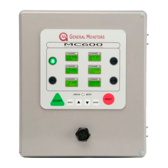
MSA General Motions MC600 Manual (151 pages)
Multi-Channel Controller for Hydrocarbon, H2S and Toxic Gas Monitoring Applications
Brand:
MSA
| Category:
Controller
| Size: 3 MB
Table of Contents
Warnings
2
System Integrity Verification
3
Commissioning Safety Systems
3
Periodic Testing/Calibration of Field Devices
3
Periodic System Verification
4
About this Manual
5
Format Conventions
5
MC600 Menu Formats
5
MODBUS Register Formats
5
Other Sources of Help
5
Related Documentation
6
Contacting Customer Support
6
Quick Start Installation Instructions
7
Table of Contents
21
Figure 10: MC600 Multi Channel Controller System
29
Figure 11: MC600 Cabinet Front Panel and Interior
30
Unpacking the MC600 Equipment
32
Table 3: MC600 Installation Overview
32
Preparing for the Installation
33
Choosing a Location
33
Tools You will Need
33
Mounting the MC600 Cabinet in Place
34
Figure 12: Mounting Dimensions for the MC600 Cabinet
34
Mounting the Sensors and Instruments
35
Sensor Location Considerations
35
Sensor Poisons
35
Mounting a Sensor with a GM Junction Box
36
Figure 13: Sensor Housing and Junction Box
36
Applying Sealants to Conduit Entries
37
Mounting a Sensor with a Duct Mounting Kit
37
Figure 14: Duct Mounting Kit Assembly
37
Connecting Sensors and Instruments to the MC600
38
Figure 15: Pre-Stripping Wiring
38
Warnings, Cautions and Standards
39
Connecting a MOS H
40
Sensor to the MC600
40
Connecting a MOS H S Sensor to the MC600
40
Figure 16: MOS H S Sensor
40
Figure 17: Connector Receptacle
40
Connecting a Catalytic HC Sensor to the MC600
41
Figure 18: Catalytic HC Sensor
41
Figure 19: Cabling Shield for HC Sensor
41
Connecting a 4-20Ma Instrument to the MC600
42
Figure 20: 4-20Ma Instrument Card
42
Figure 21: Connector Receptacle
43
Connecting a MODBUS Device
44
Connecting a HART Field Device
44
Connecting Alarm Relay Devices
44
Figure 22: MC600 MODBUD & Alarm Relay Connectors
45
Table 4: Normally Open and Closed Relay Contacts
45
Connecting Power and Starting Operation
46
Start-Up Readiness Checklist
46
Figure 23: Relay Protection for DC and AC Loads
46
Connecting the MC600 to a Power Supply
47
Figure 24: MC600 Connections to an Onboard Power Supply
47
Figure 25: Onboard Class I Division 2 Power Supply
48
Startup Process for an MC600 System
49
Figure 26: MC600 Connections to an External Power Supply
49
Figure 27: Sample Operation Mode Display
51
Configuring the Front Panel Setup
52
Maintaining the X/P Integrity
53
Basic Operation and Configuration
54
Entering and Exiting from the MC600 Menus
54
Figure 29: Front Panel Menu Display and Navigation Buttons
54
Using the Front Panel Navigation Buttons
55
Menu Flowchart Legend
55
MC600 Menu Overview
56
Figure 30: MC600 Menu Overview
56
Calibrating Catalytic HC and MOS H S Sensors
57
Calibration Schedule
58
Preparing for Calibration
58
Sensor Calibration Equipment
58
Figure 31: Portable Purge Calibration Equipment
59
Calibration Procedure for Catalytic HC and MOS H
60
Sensors
60
Figure 32: Field Calibrator (Breaker Bottle) with H
60
Stopping Sensor Calibration
61
Calibrating the LCD Display for 4-20Ma Instruments
62
Checking Calibration for Sensors
63
Inhibiting Alarms for Selected Channels
65
Using the Basic Setup Menu Options
66
Figure 33: Setup Channels Submenu
67
Configuring Alarm and Warning Set Points
68
Figure 34: Alarm Delay Setup
68
Table 5: MC600 Device Measurement Ranges, Minimum and Maximum Set Points and Increments
72
Configuring Alarm Delay Time (Ultrasonic Products Only)
73
Configuring a Calibration Point for Catalytic HC Sensors
74
Configuring the MC600 Relays
74
Figure 35: Setup Relays Submenu
75
Table 6: Default Allocation of Relays to Channels and Alarms
75
Advanced Configuration
77
Figure 36: MC600 Advanced Menu Options
77
Using the Advanced Setup Menu Options
78
Selecting a Model Option
78
Figure 37: Setup Channels, Options Model Submenu
79
Figure 38: Model Options for a 4-20Ma Signal Conditioning Card
80
Selecting the Channel Mode for the Alarm and Warning Indicators
81
Configuring Zoning (for Relay Allocation)
82
Figure 39: Option Mode Submenu
83
Table 7: Zoning Options and Relay Assignments
84
Figure 40: Zoning Submenu
85
Figure 41: Relay Assignment Options with no Zoning
86
Configuring Horn Relay
87
Configuring Card Tests
87
Figure 42: Setup Card Test Submenu
87
Configuring Setup and Inhibit Passwords
88
Figure 43: Setup Password Submenu
88
Configuring the Fault Relays
90
Figure 44: Setup Fault Relays Submenu
90
Configuring MODBUS Parameters
91
Figure 45: Setup MODBUS Submenu
91
Loading Default Settings
92
Figure 46: Setup Load Defaults Submenu
92
Using the Setup Check Menu
93
Figure 47: Setup Check Menu
94
Using the Self Test Menu
95
Figure 48: Self-Test Menu
95
Customer Support
96
Table 8: Locations
96
Maintenance
97
Developing a Maintenance Schedule
97
Calibration and Calibration Checks
97
Alternate Calibration Equipment
97
Figure 49: Remote Test Gas Applicator (TGA-1)
98
Figure 50: Three-Liter Chamber for Liquid and Solvent Vapors
98
Figure 51: H S Portable Purge Calibrator
99
Cleaning the MC600
100
Lubrication
100
Storage
100
Troubleshooting
101
MC600 Controller Error Codes and Remedies
101
Con Fail/Comm
101
Con Fail / Eeprom
101
Con Fail / Low Line
101
Con Fail / Program
101
Con Fail / Ram
101
Con Fail / Data Ram
101
Channel Error Codes and Remedies
102
Setup Channel (Sensors and Instruments)
102
Cal Channel (Sensors and Instruments)
102
Cal Fault (Sensors and Instruments)
102
Card Removed (Sensors and Instruments)
102
Fld Dev Fault (Instruments Only)
102
Invalid Card (Sensors and Instruments)
103
Sensor Fault (Sensors Only)
103
Field Device Offline
103
Mc600 Modbus Interface
104
General MODBUS Information
104
Serial Communication Settings
104
Function Codes Supported
104
Table 9: Serial Data Formats
104
MODBUS Read Protocol (Query/Response)
105
Table 10: MODBUS Read Query Message
105
Table 11: MODBUS Read Response Message
105
MODBUS Write Command Protocol (Query/Response)
106
Table 12: MODBUS Write Query Message
106
Table 13: MODBUS Write Response Message
106
Exception Response Messages and Codes
107
Table 14: MODBUS Exception Response Message
107
MC600 MODBUS Registers Summary
108
Table 15: MODBUS Exception Codes
108
Table 16: MC600 MODBUS Register Summary
112
MC600 MODBUS Register Details
113
MC600 Mode (0001H, Read-Only)
113
Unit Error Status (0002H, Read-Only)
113
Calibration and Calibration Check Mode Status (0003H, Read/Write)
113
Table 17: Bitmap for Unit Error Status (Lower Byte Only)
113
Table 18: Calibration and Calibration Check Modes
114
Model Type (0004H, Read-Only)
115
Control Card Firmware Revision (0005H, Read-Only)
115
LCD Card Firmware Revision (0006H, Read-Only)
115
Temperature (0007H, Read-Only)
115
Maximum Temperature (0008H, Read-Only)
115
Minimum Temperature (0009H, Read-Only)
115
Accept/Reset (000Ah, Write-Only)
115
MODBUS Channel 1 Address (000Fh, Read/Write)
115
MODBUS Channel 1 Baud Rate (0010H, Read/Write)
116
MODBUS Channel 1 Data Format (0011H, Read/Write)
116
MODBUS Channel 2 Address (0012H, Read/Write)
116
Table 19: Baud Rates for MODBUS Channel 1
116
Table 20: Data Formats for MODBUS Channel 1
116
MODBUS Channel 2 Data Format (0014H, Read/Write)
117
MODBUS Channel 1 Total Receive Errors (0020H, Read-Only)
117
MODBUS Channel 1 Address Errors (0021H, Read-Only)
117
MODBUS Channel 1 Function Code Errors (0022H, Read-Only)
117
MODBUS Channel 1 Starting Address Errors (0023H, Read-Only)
117
Table 21: Baud Rates for MODBUS Channel 2
117
Table 22: Data Formats for MODBUS Channel 2
117
MODBUS Channel 1 No. of Register Errors (0024H, Read-Only)
118
MODBUS Channel 1 RXD CRC Errors (0025H, Read-Only)
118
MODBUS Channel 1 Byte Timing Errors (0026H, Read-Only)
118
MODBUS Channel 1 Framing Errors (0027H, Read-Only)
118
MODBUS Channel 1 Parity Errors (0028H, Read-Only)
118
MODBUS Channel 1 Noise Errors (0029H, Read-Only)
118
MODBUS Channel 1 SCI Interrupt Errors (002Ah, Read-Only)
118
MODBUS Channel 1 Clear MODBUS Errors (002Bh, Write-Only)
118
MODBUS Channel 2 Total Receive Errors (0030H, Read-Only)
118
MODBUS Channel 2 Address Errors (0031H, Read-Only)
119
MODBUS Channel 2 Function Code Errors (0032H, Read-Only)
119
MODBUS Channel 2 Starting Address Errors (0033H, Read-Only)
119
MODBUS Channel 2 Number of Register Errors (0034H, Read-Only)
119
MODBUS Channel 2 RXD CRC Errors (0035H, Read-Only)
119
MODBUS Channel 2 Byte Timing Errors (0036H, Read-Only)
119
MODBUS Channel 2 Framing Errors (0037H, Read-Only)
119
MODBUS Channel 2 Parity Errors (0038H, Read-Only)
120
MODBUS Channel 2 Noise Errors (0039H, Read-Only)
120
MODBUS Channel 2 SCI Interrupt Errors (003Ah, Read-Only)
120
MODBUS Channel 2 Clear MODBUS Errors (003Bh, Write-Only)
120
Channel Mode (0040H for Channel 1, 0050H for Channel 2, Etc.)
120
Device Type (0041H for Channel 1, 0051H for Channel 2, Etc.)
122
Table 23: Channel Mode Descriptions
122
Table 24: Sensor Types
122
Table 25: Instrument Types (4-20Ma Instruments)
123
Sensor Full-Scale (Read-Only, 0042H for Chan 1, 0052H for Chan 2, Etc.)
124
Sensor Value (Read-Only, 0043H for Chan 1, 0053H for Chan 2, Etc.)
124
Alarm High Set Point (Read/Write, 0044H for Chan 1, 0054H for Chan 2, Etc.)
125
Alarm Low Set Point (Read/Write, 0045H for Chan 1, 0055H for Chan 2, Etc.)
125
Warning Set Point (Read/Write, 0046H for Chan. 1, 0056H for Chan. 2, Etc.)
126
Alarm State (0047H for Chan 1, 0057H for Chan 2, Etc.)
127
Table 26: Alarm States (Bit Map)
127
Sensor Life (0048H for Chan 1, 0058H for Chan 2, Etc.)
128
Calibration Point (0049H for Chan 1, 0059H for Chan 2, Etc.)
128
Alarm Mode (004Ah for Chan 1, 005Ah for Chan 2, Etc.)
128
Alarm Delay Time (004Bh for Chan 1, 005Bh for Chan 2, Etc.)
128
Mc600 Specifications
129
System Specifications
129
MC600 System Unit
129
MC600 System Unit Continued
130
4-20Ma GM Instrument Specifications
130
Mechanical Specifications
130
Figure 52: Outline and Dimensional Drawing
131
Figure 53: Outline and Dimension Drawing, Cabinet Door and Bottom
132
Environmental Specifications
133
Electrical Specifications
133
Relay Ratings
134
Output
134
Approvals
134
Table 27: VDC Cable Lengths
134
Table 28: Catalytic HC Sensor Cable Lengths
134
Table 29: MOS H
134
Sensors and Accessories
135
Catalytic Bead Hydrocarbon (HC) Sensors
135
Figure 54: Catalytic Bead, Combustible Gas Sensor
135
Catalytic HC Sensor Spare Parts and Accessories
136
Catalytic HC Sensor Part Numbers
136
Sensor Housing (Junction Box)
136
Sensor Accessories
137
Calibration Equipment
137
Metal Oxide Semiconductor
138
Sensors
138
Figure 55: MOS H S Gas Sensor
138
MOS H S Sensor Spare Parts and Accessories
139
Sensors
139
Sensor Housing (Junction Box)
139
Sensor Accessories
139
Figure 56: Movement of Electrons on MOS H S Film
139
Calibration Equipment
140
MC600 System Upgrades and Accessories
141
MC600 Upgrade Modules
141
MC600 Accessories
141
Installing Upgrades
142
Adding a Signal-Conditioning Card
142
Adding a Power Supply to the MC600 Chassis
143
Figure 57: Power Supply
143
Adding a Class 1 Division 2 Power Supply to MC600 Chassis
144
Figure 58: Power Supply Connector
144
Adding a Sounder
145
Figure 59: MC600 Class I Division 2 Power Supply
145
Figure 60: Sounder Unit
146
Figure 61: LCD Board
146
Advertisement
Advertisement
Related Products
MSA ModCon 75
MSA SUPREMATouch MCP 20
MSA FireHawk M7XT
MSA ML-3
MSA MiniCl2 10020747
MSA MiniClO2 10020745
MSA motionSCOUT K
MSA MVPC-2106
MSA MiniOX 3000
MSA MVPC2407
MSA Categories
Safety Equipment
Respiratory Product
Security Sensors
Gas Detectors
Motorcycle Accessories
More MSA Manuals
Login
Sign In
OR
Sign in with Facebook
Sign in with Google
Upload manual
Upload from disk
Upload from URL