Advertisement
Quick Links
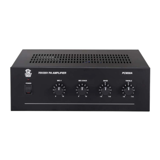
Step 1 ‐ Unbox the new amplifier (fig 1) – Set the new amplifier near the old amplifier.
Step 2 ‐ Take a picture of the back of the existing amplifier to log the output connections.
Step 3 ‐ Remove the RCA Input connection from the old amplifier – Move it to the RCA Input of the new amplifier.
This RCA male‐to‐male cord connects to the Red RCA female from the music unit.
Step 4 ‐ If connecting the 70v output to the new PCM30A amplifier, the far back right screw terminal for the 70v will be
the "positive wire," and the screw terminal next to it will be the COM "Negative" you will use.
Keep in mind there are multiple COMs. You will need to use the COM nearest to the 70v on the far back right side of
the amplifier.
Step 5 ‐ Once these two connections are complete, and the input and output on the new amplifier are verified
connected, look for a Switch on the back of the Amp near the Red/White input. It must be switched to AUX Position.
The Front of the amplifier will have a Volume knob labeled MIC2/AUX. This volume controls the input music to the
speakers. Normally you will want to set it to a 3 or 4 as to not have the music too loud.
After this is complete, you can plug the power in on the amp and turn the power button into the ON position. – If you
do not hear music, you may need to adjust the volume or the music source may not be on at this time.
For issues please call tech support with United Media Solutions at 800‐373‐8200 Opt 2
Installing a new Amplifier PCM30a
For music
input feed
Box Speakers Setup
COM
8 ohm
Standard Setup
70V
COM
Advertisement

Related Manuals for Pyle PCM30a


Summary of Contents for Pyle PCM30a
- Page 1 Installing a new Amplifier PCM30a Box Speakers Setup Standard Setup For music input feed 70V COM COM 8 ohm Step 1 ‐ Unbox the new amplifier (fig 1) – Set the new amplifier near the old amplifier. Step 2 ‐ Take a picture of the back of the existing amplifier to log the output connections. Step 3 ‐ Remove the RCA Input connection from the old amplifier – Move it to the RCA Input of the new amplifier. This RCA male‐to‐male cord connects to the Red RCA female from the music unit. Step 4 ‐ If connecting the 70v output to the new PCM30A amplifier, the far back right screw terminal for the 70v will be the “positive wire,“ and the screw terminal next to it will be the COM “Negative“ you will use. Keep in mind there are multiple COMs. You will need to use the COM nearest to the 70v on the far back right side of the amplifier. Step 5 ‐ Once these two connections are complete, and the input and output on the new amplifier are verified connected, look for a Switch on the back of the Amp near the Red/White input. It must be switched to AUX Position. The Front of the amplifier will have a Volume knob labeled MIC2/AUX. This volume controls the input music to the speakers. Normally you will want to set it to a 3 or 4 as to not have the music too loud. After this is complete, you can plug the power in on the amp and turn the power button into the ON position. – If you do not hear music, you may need to adjust the volume or the music source may not be on at this time. For issues please call tech support with United Media Solutions at 800‐373‐8200 Opt 2 ...
- Page 2 InfoLink 4 Port Call Button Interface Installation 1. Connect call button wiring to interface. Strip ¼” to no more than 3/8” insulation from wiring. The small square buttons near each connection when pressed will release the spring loaded wire capture mechanism. Depress when inserting wires. A small flat screwdriver can be used for this purpose.
- Page 3 Replacement Preset SanDisk Thumb Drive to Restore Music Fig 1 Fig 2 Fig 3 There is no need to ship back your UMS music player for a replacement unit. Instead, please locate the enclosed preset SanDisk thumb drive. This will replace your existing SanDisk thumb drive and restore music at your location.
- Page 4 McCoys Lumber Install The United Media Solutions PC-Lan based music system. The Unit will need to be connected with a Network cable - this is how the music unit communicates channel changes and updates for music and messages. Installing your UMS LAN connected box. Network Cable Power Cord1 Find the current Sirius System and place the new system nearby.
- Page 5 Info-Link SiriusXM GPRS SIM Chip Exchange Fig 3 Wireless Modem Your new SIM chip is enclosed (fig4). Please locate SiriusXM Fig 2 your music system and find (fig1) SiriusXM Receiver. Antenna Cable Step 1 - The existing SIM chip (see fig2) is located on the wireless modem (fig3).
- Page 6 Fig. B Fig. A Fig. C Exchanging the Power Supply for the SiriusXM radio Step 1. Locate the SiriusXM music system. Step 2. Press the Red Button on the power strip to turn off power (fig A). Step 3. Remove the cable as indicated from the SiriusXM radio (fig B). Step 4.
- Page 7 Info-Link SiriusXM Setup Please call your account representative upon receiving the system. SiriusXM Antenna Cable Step 1 - Using the included power strip (Fig Fig 3 SiriusXM Receiver 1) plug the system into a wall outlet with the system near an external wall. Step 2 - Place the provided SiriusXM Antenna (fig 2) near the window pointed Fig 1...
- Page 8 Platinum MP-3000 Installation Guide 1. Locate your existing Protege/Audio Emcee MOH player. 2. Locate the audio cord that connects your Protege/Audio Emcee player to the telephone system. a. On XE-500 models, the audio cord connects on the front of the player. [FIG1] b.
- Page 9 - InfoLink PC Installation Manual - System Component Overview 1...
-
Page 10: System Installation
- System Installation - General Installation Considerations • Every effort should be made to maintain defined wiring color codes. • The power strip is provided for powering of accessories if necessary. • All Audio outputs are Line-Level and should be connected to High Impedance loads only! •... - Page 11 Sirius Antenna Aiming Guidelines Antenna Antenna mounted outside System Interface Connections System audio outputs are provided via a 3.5mm to Stereo Female Phono adapter. The MOH channel is present on the left channel (White Connector) and the Overhead channel is present on the right channel (Red Connector)
- Page 12 Cable Connection The Info-Link System will come with MOH and overhead cable connected to the system. The connector plug labeled MOH connects to the MOH port on the telephone system. The connector plug labeled Overhead connects to the back of the amplifier. The MOH cable connects to a mini plug (already attached), that plugs into the Nortel phone system (See picture below).
- Page 13 The existing amplifier (below) will have a blue split cable connected to the AUX port (pictured below). Remove the blue cable and discard. Amplifier Back of amplifier with existing blue coupler Plug the RCA extender cable labeled “Overhead” (no miniplug connected) into the Left side Auxiliary port on the amplifier (see diagram for Auxiliary port location).
- Page 14 MOH source is across pins 3 and 6 on the RJ45 connection into the V&M Module. V & M Module Programming Features that affect MOH: 1. Impedance 2. Operation – should be 4 wire from what I remember 3. Music-threshold Vic E &...
- Page 15 Making the Overhead Connection Connect the Overhead output to the site’s overhead system input/amplifier using a male-to-male RCA patch cord. The Overhead output can drive several hundred feet of low capacitance wiring if necessary. Making the Phone Line/Modem connection The system requires a phone line connection for proper operation. The system is equipped with either an internal modem, or an external USB modem.
- Page 16 TABLE OF CONTENTS Loaf n Jug Possible issues and music swap out procedure. Page 1 Opening page, Picture of LNJ Site. Page 2 Table of Contents Page 3 1 ‐ 2 GPRS Positioning. Page 3 3 Rebooting the System. Page 4 1 ‐ 2 Antenna Signal. Page 4 3 Adjusting & Securing the Antenna. Page 5 4 ‐ 6 Audio Output Cords. Page 5 7 Amplifier Outputs & Settings. Page 6 8 ‐ 9 Amplifier Outputs & Settings. Page 6 1 Audio Troubleshooting Page 6 2 ‐ 4 Sirius Tuner and antenna troubleshooting. Page 7 1 ‐ 3 Numeric Key Pad Hookup and Troubleshooting. Page 7 1 – 4 USB Modem and Dial tone. Page 8 1 ‐ 4 Simple Swap out and Install Guide. Page 9 1 ‐ 6 Simple Swap out Install and Finish. Required Tools: ...
- Page 17 CONFIDENTIAL Do Not Copy or Disclose FOR INTERNAL PURPOSES ONLY Loaf N Jug Possible Music Issues and Music Unit Swap Out Procedure You must call United Media Solutions Tech Support to clock‐in before you begin any work. You will also have to call to clock‐out once you are finished. Please contact us with any and all questions. Be courteous and professional ‐ you represent United Media Solutions. The United Media Solutions PC is a music‐based PC with a GPRS and analog modem set up ‐ this is how the music unit communicates channel changes and updates for music and messages. 1. Turn on the unit before you mount it to the wall. This will Fig1 ensure the GPRS modem will get an adequate signal when it is mounted. You will need to check the GPRS signal indicator located by the antenna attached to it (Fig1). Once the light on the GPRS modem is solid green, you may mount the unit and begin working. 2. If this unit is already mounted (Fig2), verify the light is solid green. Once you have the unit in position, you will reboot the Music PC from the surge protector. 3. To reboot the Music PC, simply turn the power off at the surge protector, wait a few seconds, then turn it back on. Once the unit boots up, the light on SiriusXM tuner will appear red for about 20 seconds. It will then alternate clear to red, then green. Once it is green, the PC will start the Link2 PC software that runs the music messaging and SiriusXM tuner. If everything is working properly, music will start playing. Fig2 The PC unit sends music from the unit to the amplifiers. There is usually a Y splitter in place with a Red and White RCA cord that splits the left and right channel music content and sends music to both amplifiers, and from the amplifiers to speakers inside and outside the store. ...
- Page 18 1. Find the audio output jack that is plugged into the headphone jack and detach it from the unit. As long as the 3.5mm Cord is unplugged, the unit will play music on the box itself. 2. Regardless of the music unit working or needing to be troubleshot further, you must connect a Monitor “VGA” Keyboard/Mouse “USB” to the PC to connect to our Network Operations Center (NOC). Once you have your Monitor Keyboard and Mouse hooked up to the unit, whether or not the music is back on and playing, you will need to look at the signal through the Link2PC software. The Link software auto plays and will be up and running on the screen. Locate the box inside the software labeled Sirius SID. You will see the 12‐digit tuner ID. The tuner ID is also located on the SiriusXM Hardware. The SiriusXM SID lists artist title and track. If for any reason is says “Call 800‐Sirius or reactivate,” stop immediately and call United Media Solutions. Otherwise there will be 3 bars as signal indicators. 1. Hover your mouse over the signal indicators; they are labeled composite/satellite/terrestrial, and the status of the signal in the bars will read excellent‐good‐poor‐weak. Any reading less than good means we need to adjust the antenna. The 3 bars will be filled with blue blocks indicating signal strength. This is helpful when adjusting the antenna to find optimum signal. Fig3 See Fig3 of SiriusXM antenna. It is roughly 3”x4” and will have a XM or Sirius Logo on it. 2. The antenna opens and closes like a clam shell. This antenna must be positioned to point straight up. 3. The antenna can also be adjusted slightly to point toward Wisconsin, meaning the logo must point toward the sky and or a couple centimeters / degrees toward WI. The screw mounts must point towards the ground like a clam shell closed. Once you correct to a good or better signal, and make sure the music is working constantly, you can mount it with silicone or zip ties to an AC condenser or pipe jack. The Status light on a Sirius radio can only be in one of the following states: State ...
- Page 19 Fig4 4. Next you will need to trace the output cord from the headphone jack (Fig4) 5. Confirm it is intact and connected to the amplifier using a Y split and a male to male RCA (Fig5) 6. There will be a 3.5mm Y splitter that has a red end Fig5 indicated below. Sometimes there is a male RCA to female red/white Y splitter (Fig6) This sends music to the inside/outside amplifier. This will send one zone of music to two different zones. The red end should have a male to male RCA cord connected into it that runs to the AUX input on the amplifier (Fig7) that controls the overhead music. Fig7 Fig6 The AUX input is the red RCA Input on the back of the amplifier (Fig8). The amplifiers are normally Pyle home PCM20s or PCM30s. Fig8 7. Once you have verified the cords are connected correctly, set the interior amplifier speaker run output on 70v and COM terminals on the right side of the back of the amplifier. Set the outside speaker connections on the left side 8ohm and COM terminals for output connections. The store’s speakers are run in a daisy chain. Once that is verified, you will need to adjust the volumes to the manager’s request. ...
- Page 20 8. Test with an alternate audio source (any type of media player, cell phone, etc.). Do this if you do not have music output from our unit. This will test the amp functionality. If it is working properly, so should our music unit. 9. Check the Amp and confirm it has power. Check the volume and input settings. You can check this on the PC as well. These might need to be adjusted. If you do not hear music, you will need to determine where the music is getting stopped. Replace the components or correct the issues as needed. If the connections are nice and tight and you have no music, troubleshooting the unit will be necessary. The Sirius tuner (Fig9) will tell the tale. 1. If the tuner has a green light and audio is working on the PC, you will need to test the audio output with a pair of headphones or a Butt in set – plug it into the Music PC. If Fig9 music works though 1 or 2 headphones or on both channels, you know the issue is with the AUX wiring. Correct the AUX wiring. Check the speaker wiring or the amplifier. It is noticeable if something is disconnected. Repair the connections as needed. 2. If the music is not working through the PC, double check the tuner light. An orange light indicates a low signal, and the antenna will need to be adjusted further. Fig10 3. If the tuner light is alternately blinking red and clear, that indicates the antenna is disconnected and must be traced forward from the tuner to the end, which is usually on the roof. It uses compression fittings called SMB‐F Connectors (Fig10). 4. You will need to confirm this connection is snapped into place. Our Fig11 SiriusXM antennas are usually extended with a RG6 cable with F connectors (Fig11) to attach the antenna and connect to the SiriusXM tuner. Usually toning or visually looking at this RG6 Coax cord will tell you what is wrong. If something is broken or cut, you will need to cut the RG6 back a few feet on weathered or water damaged ends, then re‐terminate an F‐connector. This should resolve any and all issues. Take pictures and upload. ...
- Page 21 Now that music is on and working you will need to locate the Triggered Message Numeric Keypad (Fig12) 1. This item is usually located at the front counter. It is a key pad Fig12 extended using Cat 5 to our unit – It connects to our unit using a RJ45 adapter as shown in reference picture. Test its functionality by pressing the 1 key on the key pad. 2. If it works, please note it. 3. If it does not work, you will need to trace and correct the Cat 5 Extension. This allows for an employee to trigger a message from the counter. The keypad actuates a message prompt in our software, pauses the music, and plays the message prompt overhead. ONCE MUSIC IS WORKING in the store and outside the store, you will need to connect our unit to our network for Connectivity Verification: You must test the telephone line connected to the USB Modem (Fig13) for dial tone. Fig13 1. If there is no dial tone, you must trace the phone line and correct dial tone. It could be disconnected from the D‐mark or Unplugged from a fax machine or phone jack splitter. 2. Once you restore dial tone to the USB modem and have the system powered up and playing, disconnect power from system. 3. Turn off the surge protector. Do NOT use the power button. The system must lose power during normal operation. 4. Leave power disconnected for 3 to 5 seconds then reconnect. ...
-
Page 22: Installation
If system does not automatically power on when power is reconnected, please contact United Media Solutions technical support @ 800‐373‐8200. When the system experiences a power loss or other unexpected failure, it will initiate a session with our server on start up. Regardless, it is required that you contact United Media Solutions technical support @ 800‐373‐ 8200 after this power cycle to verify that the system is communicating normally with our servers. Call after music is restored. For efficiency, while on the phone with technical support, it is recommended that message volume be tested as well. This means triggering a message and confirming it is balanced with the music. You will need to keep your monitor plugged in throughout the service call as you will need to view your display for Tech Support Questions. Installation Simple swap out: Select a location for the system: either a manager’s office or UMS specified location in the Work Order. The following factors need to be weighed when selecting a location for the system, ranked from most important to least important. 1. Distance from connection points: The system will be connected to power, an audio amplifier and a telephone D‐mark or fax machine, or in some cases, a network interface (switch, router, etc. as specified). Locate and mount the system so all provided cabling will reach required devices. If this is not possible, locate system to minimize cable runs. 2. Air Flow / Cooling: System should have sufficient clearances for adequate cooling air flow. Under no circumstances shall the system be located on top of or in close proximity to heat generating equipment (amplifiers, computers, radiators, etc.) or in enclosed or tight spaces. 3. Accessibility and Visibility: The system should be located such that it is out of the way of day to day activities of the site, yet still be accessible and visible should on‐site personnel need access for troubleshooting, reset, etc. 4. Site Personnel Preferences: Some managers or other authoritative site personnel may have strong opinions about where the system should be located. If possible, do you best to accommodate them or suggest potential alternatives, keeping in line with the above factors. ... - Page 23 Audio: 1. If the location has an existing sound system and music source, simply locate the cable coming from the existing sound system leading to the headphone jack on the old system, disconnect it from the old unit, and connect it to the output on the new Music Maestro. If the existing input is stereo, unplug both left and right inputs, and connect the mono output from our system to the amplifier in the AUX in red. 2. If the location has an existing sound system, and no music source (or it’s not connected) you’ll need to locate the appropriate input for the music. Very rarely is it known what make/model of amplifier is in place, so it may be necessary to consult the manual for the amplifier if the music input is not obvious. Typically, the input will be labeled Aux, Auxiliary, Music in, CD, Tape, Input 1, Input 2, etc. 3. Locate the nearest phone jack, fax machine or D‐mark, and connect dial tone to the USB modem on the unit. In some cases, we have provided a new patch for the switch to connect to our unit then to the assigned switch on the assigned port number. The finished Installation (Fig14) should be neat clan and professional. Fig14 5. Reboot the unit and call United Media Solutions to ensure the unit is connected to NOC @ 800‐373‐8200 Option 2 6. Find the shipping label provided and ship back the old and unused required equipment. This includes the old SiriusXM tuner, modems, surge protectors, etc. ...
Need help?
Do you have a question about the PCM30a and is the answer not in the manual?
Questions and answers