Table of Contents
Advertisement
Quick Links
Advertisement
Table of Contents

Subscribe to Our Youtube Channel
Related Manuals for CDA EVPK90


Summary of Contents for CDA EVPK90
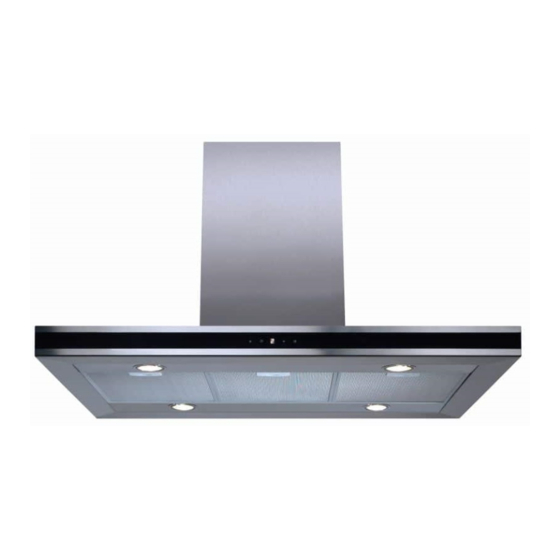
- Page 1 EVPK90 Island Extractor Installation, use and maintenance www.cda.eu...
-
Page 2: Table Of Contents
Contents: Important information Important safety warnings Using your extractor Intensive function Clean air function Care and maintenance Changing the charcoal filter Changing a light bulb Mains electricity connection Electrical information Troubleshooting Installation - preparation Ducting Installation Installation - assembly Installation - mounting If re-circulating Energy efficiency information... - Page 3 Appliance information: Please enter the details on the appliance rating plate below for reference, to assist CDA Customer Care in the event of a fault with your appliance and to register your appliance for guarantee purposes. Appliance Model...
-
Page 4: Important Information
Declarations of Conformity: This appliance has been manufactured to comply with all EU & UK statutory requirements and complies with all applicable legislation and following European directives: • The Low Voltage Directive 2014/35/EU • Electromagnetic Compatibility Directive 2014/30/EU The product has been marked with the UKCA and CE symbols. This appliance is marked according to the European directive 2004/104/EC on Waste Electrical and Electronic equipment (WEEE). -
Page 5: Using Your Extractor
Do not use silicone sealant to secure the hood to the wall. • You must be able to isolate the extractor from the mains electrical • supply after installation. Steam cleaners must not be used when cleaning this appliance. • The performance of your extractor will vary depending on a •... -
Page 6: Intensive Function
To switch on the extractor • Touch either key “B” or “D”. The appliance will switch on at the first speed. • To increase the speed touch key “D”. • To switch the extractor off, touch and hold key “B” for two seconds when the extractor is working at higher speeds, or touch key “B”... -
Page 7: Care And Maintenance
Care and maintenance IMPORTANT: DO NOT PERFORM MAINTENANCE OR CLEANING OF THE EXTRACTOR WITHOUT FIRST SWITCHING OFF THE ELECTRICITY SUPPLY. Cleaning Fig. 2 You should use a nonabrasive cleaner. Any abrasive cleaner (including Cif) will scratch the surface and could erase the control panel markings. -
Page 8: Changing The Charcoal Filter
To remove the grease filters 1. Pull open the handle on each grease filter as shown in fig. 2. It will release at the handle side. 2. Lower the grease filter to remove it completely. To replace the grease filters Repeat the steps above in reverse order. - Page 9 Changing the light IMPORTANT: THE LIGHT BULBS SHOULD ONLY BE CHANGED BY CDA AUTHORISED SERVICE AGENTS. IF ONE OR MORE OF YOUR BULBS FAIL, CONTACT CDA CUSTOMER CARE TO ARRANGE A SERVICE VISIT. DO NOT TOUCH THE LIGHT BULBS IMMEDIATELY AFTER USE AS THE BULB MAY BE WARM/HOT.
-
Page 10: Mains Electricity Connection
Mains electricity connection DOUBLE POLE SWITCHED THIS APPLIANCE MUST BE FUSED SPUR OUTLET CONNECTED TO THE MAINS SUPPLY BY A COMPETENT PERSON, USING FIXED WIRING VIA A DOUBLE POLE SWITCHED FUSED SPUR OUTLET AND PROTECTED BY A 3A FUSE. USE A 3 AMP FUSE The appliance must be connected by a qualified electrician, who is a member of the N.I.C.E.I.C. -
Page 11: Electrical Information
Assembly and electrical connection should be carried out by competent personnel. When installing this product we recommend you seek the help of another individual. IMPORTANT: THIS APPLIANCE IS A CLASS II APPLIANCE (DOUBLE INSULATED) AND IS NOT INTENDED TO BE EARTHED. DO NOT FIT AN EARTH LEAD TO THIS EXTRACTOR. -
Page 12: Installation - Preparation
Installation - preparation The extractor is intended to be mounted directly to a solid ceiling using fixings appropriate for the ceiling. When the extractor is to be installed above an electric hob, the minimum distance between the hob and extractor Gas: 750mm recommended. -
Page 13: Ducting
Ducting The ducting used should be 150mm, rigid circular pipe and must be manufactured from fire retardant material, produced to BS 476 or DIN 4102-B1. Wherever possible utilise rigid circular pipe which has a smooth interior, rather than the expanding concertina type ducting. The lengths of ducting with minimal effect on performance are as follows: •... -
Page 14: Installation
Installation We recommend that you seek the help of another individual when installing this product. Always wear adequate PPE (Personal Protective Equipment) for the task at hand. This product may have sharp edges; always protect your hands. • Connect the electronic control box and ducting pipe to the motor body before proceeding with the installation. -
Page 15: Installation - Assembly
Installation - assembly 1. Place the extractor body on a protected table & fix the cage sections (D in Fig. 10) using the supplied screws (E in Fig. 10). 2. Remove the screws (A in Fig. 11) fastening the lower and upper cage sections (B in Fig. -
Page 16: Installation - Mounting
4. Assemble the upper and lower cage section at the desired height as calculated in step 3. Use the screws highlighted with ‘G’ in Fig. 5. When the cage sections have been securely fastened together, fit the upper (B in Fig. 13) and lower (A in Fig. 13) chimney sections over the cage sections as shown in Fig. - Page 17 3. With the help of another individual, locate the extractor on the three exposed ceiling screws and rotate into position. Tighten the three screws and then secure the whole assembly into position using a final screw in hole ‘X’ in Fig. 15. Fig.
- Page 18 4. IF THE EXTRACTOR IS TO BE USED AS A RECIRCULATION DEVICE (filtering the air before recycling it into the kitchen) then the vent diverter needs to be fitted. Fit the diverter to to the upper cage section (Fig. 17) and then connect the ducting to it. 5.
-
Page 19: Energy Efficiency Information
Sound power level 64.0 Grease Filter Efficiency 72.0 (D) Hood c i f 45 (A) Hood E & O E. All instructions, dimensions and illustrations are provided for guidance only. CDA reserve the right to change specifications without prior notice. - Page 20 For more information please contact: The Sales Department on 01949 862 010 or email sales@cda.eu Customer Care Department. The CDA Group Ltd, Harby Road, Langar, Nottinghamshire, NG13 9HY 01949 862 012 F: 01949 862 003 E: customer.care@cda.eu www.cda.eu...
Need help?
Do you have a question about the EVPK90 and is the answer not in the manual?
Questions and answers