Table of Contents
Advertisement
Advertisement
Table of Contents

Related Manuals for CDA EVS90BL


Summary of Contents for CDA EVS90BL
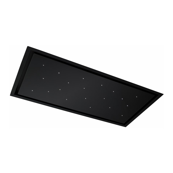
- Page 1 EVS90BL Ceiling extractor Installation, use and maintenance www.cda.eu...
-
Page 2: Table Of Contents
Contents: Important Important information Using your extractor Care and maintenance Removing the grease filters 10 - 14 Installation Installation preparation - height Cut-out information Fitting the extractor Fitting the motor group Ducting Mains electricity connection Electrical information Troubleshooting Energy Efficiency Information... -
Page 3: Important
Appliance information: Please enter the details on the appliance rating plate below for reference, to assist CDA Customer Care in the event of a fault with your appliance and to register your appliance for guarantee purposes. Appliance Model... -
Page 4: Important Information
EU Declarations of Conformity: This appliance has been manufactured to the strictest standards and complies with all applicable legislation, including Gas safety, Electrical safety (LVD) and Electromagnetic interference compatibility (EMC). IMPORTANT INFORMATION FOR CORRECT DISPOSAL OF THE PRODUCT IN ACCORDANCE WITH EC DIRECTIVE 2012/19/EU. At the end of its working life, the product must be taken to a special local authority waste collection centre or to a dealer providing appliance recycling services. - Page 5 IMPORTANT: Under no circumstances should the extractor be • connected to any gas ventilation system, flue system or hot air ducting system. • Do not vent the extractor into an attic or loft space. • Only house the extractor in rooms with adequate ventilation.
-
Page 6: Using Your Extractor
Using your extractor For best performance, you should switch on the extractor 15 minutes before starting to cook and leave it to run for approximately 15 minutes after the end of cooking (you can use the timer function for this). 1 - On/off button 2 - Speed increase button 3 - Speed decrease button... - Page 7 Timer The extractor is equipped with a timer that allows the extractor to run for 15 minutes before switching off automatically. - To activate the timer, set the desired speed and then press and hold the speed decrease button (3) for approximately two seconds. The LED indicator for the speed on the extractor body will flash to confirm the timer is active.
-
Page 8: Care And Maintenance
Care and maintenance IMPORTANT: DO NOT PERFORM MAINTENANCE OR ATTEMPT TO CLEAN THE EXTRACTOR WITHOUT FIRST SWITCHING OFF THE ELECTRICITY SUPPLY. ALWAYS WEAR ADEQUATE PPE (PERSONAL PROTECTIVE EQUIPMENT) FOR THE TASK AT HAND. Cleaning You should use a non-abrasive cleaner. Any abrasive cleaner (including Cif) will scratch the surface and could erase the control panel markings. - Page 9 These are not user-replaceable. In the unlikely event of a failure please contact CDA Customer Care using the details on page 17. The lighting is designed for aesthetic purposes and not for general room, nor down-light, illumination.
-
Page 10: Installation Preparation - Height
Equipment) when handling. Installation preparation - height IMPORTANT: When the extractor is to be installed above a CDA electric hob, the minimum distance between the hob and the downwards-facing side of the extractor must exceed 650mm. When the extractor is to be installed above a CDA gas hob, the minimum distance between the hob and the downwards-facing side of the extractor must exceed 650mm. - Page 11 IMPORTANT: Ensure that any false ceiling will be capable of supporting the weight of the product, which is approximately 18.7 kg (without the motor group). Your motor group should be mounted onto a solid ceiling or wall. Below (Fig. 2) is a diagram showing the overall extractor dimensions. This is to aid you in preparation for installing the extractor.
-
Page 12: Fitting The Extractor
Installation - fitting the extractor Offer up the extractor to the cut-out/niche that you have prepared. You may have to manoeuvre it slightly to get the extractor and hangar hooks (A,B,C and D in Fig. 3) into the cut-out. With at least two others supporting the extractor, tighten the screws that are accessible through four holes on the downwards facing side of the extractor (Fig. -
Page 13: Fitting The Motor Group
Installation - fitting the motor group The motor group can be placed wherever is most convenient. We strongly recommend that the motor group is fitted to a solid ceiling or wall. There are four screw holes on one of the motor group sides to facilitate this. -
Page 14: Ducting
Ducting The ducting used should be 150mm, rigid circular pipe and must be manufactured from fire retardant material, produced to BS 476 or DIN 4102-B1. Wherever possible utilise rigid circular pipe which has a smooth interior, rather than the expanding concertina type ducting. The lengths of ducting with minimal effect on performance are as follows: •... -
Page 15: Mains Electricity Connection
Mains electricity connection THIS APPLIANCE MUST BE CONNECTED TO THE MAINS SUPPLY BY A COMPETENT PERSON, USING FIXED WIRING VIA A DOUBLE POLE SWITCHED FUSE SPUR OUTLET AND PROTECTED BY A 3A FUSE. Warning! This appliance must be earthed We recommend that the appliance is connected by a qualified electrician, who is a member of the N.I.C.E.I.C. -
Page 16: Electrical Information
Note: Use a 3A Fuse Assembly and electrical connection should be carried out by specialised personnel. The mains isolation switch should be readily accessible after the appliance has been installed and it is recommended that the isolation switch is located within 2m of the appliance, where practical. This appliance is intended to be connected to the mains electrical supply by means of an isolation switch and fused spur and is intended to be protected by a 3A fuse. - Page 17 2. Check whether the extractor still extracts on any speed. If not, check the fuse and remote batteries, as above. If the lights still do not work, contact CDA Customer Care. Contact details are on page 17. If the remote control is responding incorrectly or not at all: 1.
- Page 18 NOTES:...
-
Page 19: Energy Efficiency Information
Measured power consumption in 0.39 standby mode Sound power level 76.1 (C) Hood c i f 15 (D) Hood E & O E. All instructions, dimensions and illustrations are provided for guidance only. CDA reserve the right to change specifications without prior notice. - Page 20 For more information please contact: The Sales Department on 01949 862 010 or email sales@cda.eu Customer Care Department. The CDA Group Ltd, Harby Road, Langar, Nottinghamshire, NG13 9HY 01949 862 012 F: 01949 862 003 E: customer.care@cda.eu www.cda.eu...
Need help?
Do you have a question about the EVS90BL and is the answer not in the manual?
Questions and answers