Table of Contents
Advertisement
Quick Links
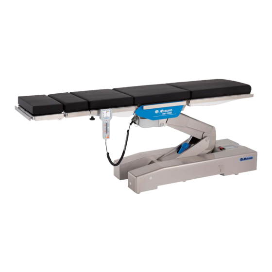
Microsurgery Operating Table Operator's Manual
MST-7300B
MST-7300BX
This operating table is designed for medical operations. Using this operating table for any
other purpose other than this intended use may cause serious injury.
The operator and the person in charge of the maintenance of this operating table must read
this operator's manual thoroughly and understand the contents before operating, inspecting,
adjusting and maintaining it.
Keep this manual for reference in a place where is readily accessible.
MES-CK18-350-10EN Ver.6 2021-10-01
Advertisement
Table of Contents

Related Manuals for Mizuho MST-7300B


Summary of Contents for Mizuho MST-7300B
- Page 1 Microsurgery Operating Table Operator's Manual MST-7300B MST-7300BX This operating table is designed for medical operations. Using this operating table for any other purpose other than this intended use may cause serious injury. The operator and the person in charge of the maintenance of this operating table must read this operator's manual thoroughly and understand the contents before operating, inspecting, adjusting and maintaining it.
-
Page 2: Table Of Contents
Table of contents Introduction ………………………………………………………… 1 This manual ……………………………………………………………………… 1 Intended use and this product ………………………………………………… 1 Operation of this product ……………………………………………………… 2 Accessories ……………………………………………………………………… 2 Safety precaution ………………………………………………… 4 Read thoroughly before using ………………………………………………… 4 Labeling ………………………………………………………………………… 9 Section Introduction ………………………………………………13 Main unit …………………………………………………………………………13 Touch screen...……………………………………………………………………14 Control unit ………………………………………………………………………19... - Page 3 Operation ……………………………………………………………37 Display the monitor ………………………………………………………………37 Operating the emergency stop switch …………………………………………38 6.3 Fixing and unfixing the operating table ………………………………………39 Tilting the tabletop laterally ……………………………………………………40 Trendelenburg ……………………………………………………………………41 Bending the back plate …………………………………………………………43 Bending the leg plate ……………………………………………………………45 Changing the tabletop height …………………………………………………46 Sliding the tabletop (MST-7300BX only) ………………………………………48 6.10 Operating/Registering memory…….…………………………….……………..50 6.11 Checking the current position of the tabletop …………………………………54 6.12 Returning to level ………………………………………………………………55...
-
Page 5: Introduction
. Introduction 1.1 This manual This manual contains information for safely and effectively using this product. Before operating this product, read this manual thoroughly to understand how to operate and inspect the product. Failure to follow these instructions could lead to serious injury. The safety information is categorized as per the following so that the contents of warnings and cautions, and the details of warnings and cautions which are labeled on the product may be comprehended. -
Page 6: Operation Of This Product
1.3 Operation of this product The description of the operations written in this manual focuses mainly on those to be done by the control unit. For some operations operable only by the touch screen, however, those by the touch screen are described. - Page 7 „ „ Optional Foot switch Control unit charging adapter...
-
Page 8: Safety Precaution
. Safety precaution 2.1 Read thoroughly before using Never perform the following when you use the product. Otherwise, damage to the operating table, electrical shock, and/or fire may occur. Any serious incident that has occurred in relation to the device should be reported to the manufacturer and the competent authority in which the user and/or patient is established. (1) Head plate and leg plate Do not step or sit on the head plate or the leg plate(s). - Page 9 When transferring a patient from an operating table (Fig. a) or changing a patient’s body position (Fig. b), do not apply excessive force to the head plate or leg plate. CAUTION The operating table may get deformed or damaged. Fig. a Fig.
- Page 10 „ „ Patient's position during surgical operation • Make sure to always securely attach the mattresses to the operating table so that they do not come off. WARNING The mattresses may come off, and the patient may get injured. • Position the patient's body 10 mm (0.39 in) or more away from the metal side rail. The side rail may produce high temperatures due to the usage of electric scalpels, etc., which may result in a burn injury.
- Page 11 4. As with step 3, disinfect the surfaces of the tables and side rails. 5. Wipe off the operating table with a clean dry cloth 15 minutes after disinfecting it. • Make sure to use Mizuho authorized disinfectants. The disinfectants are as shown below.
- Page 12 ● Moving and transporting • Do not move the operating table with a patient on it. CAUTION • Follow the procedures below to move the operating table. * Before moving the operating table, disinfect the entire operating table in order to prevent infection.
-
Page 13: Labeling
2.2 Labeling The operating table is labeled at the locations shown as below. Before use, make sure to understand the contents of the labels. „ „ Warning and Caution labels (7) (8) (1) C643013 (2) C643012 (3) C657332 ... - Page 14 (14) (18) (15) (21) (19) (17) (16) (23) (22) (20) (10) C657337 (MST-7300BX) (10) C657335 (MST-7300B) (11) C657336 (MST-7300BX) (11) C657334 (MST-7300B) (12) C657343 (13) C642002 (14) C657313 (15) C657309 (16) C657308 ...
- Page 15 „ „ Other labels (2/2) (30) (30) (30) (30) (30) (26) (27) (28) (29) (31) (32) (33) (34) (35) (26) C657305 (ASIA) (27) C657303 (ASIA) (28) C657302 (ASIA) (29) C657301 (ASIA) C657348 (EU) C657351 (EU) C657349 (EU) C657350 (EU)
- Page 16 „ „ Symbol mark for labeling Symbol Description Label no. Indicates a possibility of injury or even death if operates the (1) (2) (3) (5) (6) (7) table without following the warning (8) (9) General prohibition sign (3) (5) General mandatory action sign. (3) (5) (6) Emergency stop Refer to the operator's manual...
-
Page 17: Section Introduction
. Section Introduction 3.1 Main unit Auxiliary Head plate (*1) Back plate (*1) Seat plate Leg plate (*1) back plate (*1) Head plate Leg plate flexing lever attaching/ detaching lever Head plate fixing handle Mattresses Auxiliary back plate fixing handle Back plate attaching/detaching Fig. -
Page 18: Touch Screen
3.2 Touch screen „ „ TOP PAGE screen Power source (AC/BATTERY) Operation speed (LOW/HIGH) Position in operation Memory mode being used Completion of memory position ISO CENTER mode (MST-7300BX only) CAUTION/WARNING screen (Refer to Fig. E-1, E-2) Battery indicator BACK-UP CONTROLS screen (Refer to Fig. B-1) Select Stop at Level screen (Refer to Fig. - Page 19 „ „ BACK-UP CONTROLS screen (2/2) Brake unlock Level (Tap more than 1 second) High speed Low speed ISO CENTER mode Buzzer at limit of travel (MST-7300BX only) MEMORY FUNCTION Reset memory screen Setup memory Page TOP PAGE screen Fig. B-2 (MST-7300BX) „...
- Page 20 „ „ Select Stop at Level screen Trendelenburg Lateral tilt Back plate bending Pause ON/OFF Head-to-foot slide (MST-7300BX only) Right-to-left slide (MST-7300BX only) Leg plate bending TOP PAGE screen Fig. D (MST-7300BX) NOTE • With the default setting, all functions are set to ON. • For the details of the Select Stop at Level screen, refer to Page 31.
- Page 21 „ „ CAUTION/WARNING screen CAUTION No. Title Content Details (Refer to Fig. E-1) Go to the previous screen TOP PAGE screen Fig. E-1 Fig. E-2 NOTE • To prevent damages, the operating table may stop during operation and a caution/warning screen such as in Fig. E-1 appears on the touch screen. For specific recovery procedures after the operating table stopped, refer to Page 77.
- Page 22 „ „ SUPPORT screen TOP PAGE screen Fig. F NOTE Please contact your distributor or Mizuho for repair or maintenance.
-
Page 23: Control Unit
3.3 Control unit „ „ MST-7300BX Battery power status Brake status Menu number SPEED Speed status HIGH Battery level Caution and warning Current position Control unit charge PILOT lamp request lamp Menu switch: Display table position/ Enter switch: Set position Set memory Memory switch: Level/Center lamp... - Page 24 „ „ MST-7300B Battery power status Brake status Menu number SPEED Speed status HIGH Battery level Caution and warning Current position Control unit charge PILOT lamp request lamp Menu switch: Display table position/ Enter switch: Set position Set memory Memory switch:...
-
Page 25: Foot Switch (Optional)
3.4 Foot switch (optional) „ „ MST-7300BX and MST-7300B Reverse Trendelenburg: Lateral tilt: Table up Head up Right down Table down Trendelenburg: Lateral tilt: Head down Left down... -
Page 26: Installation
. Installation 4.1 Installation of the operating table This product requires the installation space shown as below. 2.5 m (98.43 in) or more 2.5 m (98.43 in) 2.5 m (98.43 in) or more or more 2.5 m (98.43 in) or more •... -
Page 27: Attaching/Detaching The Control Unit
4.2 Attaching/Detaching the control unit „ „ Attaching the control unit Align the connector with the guide and insert it into the receptacle properly. Insert the connector „ „ Detaching the control unit Turn the connector ring in the direction of the arrow until it stops. - Page 28 „ „ Using the control unit wirelessly The control unit can be detached from the main unit and used wirelessly. „ Putting the control unit to the wireless control status Hold the connector body to detach it. Holding the cord to detach the connector may cause breaking CAUTION of the cord.
- Page 29 „ Charging The control unit cannot be used wirelessly when the battery level NOTE is low. If the control unit charge request lamp at the upper right of The battery of the control unit the control unit lit on, connect the control unit with the cord and can be recharged only when immediately charge the control unit.
-
Page 30: Turning On/Off The Power
• Connect the product to the power source provided with the protective grounding to prevent the risk of an electrical shock. CAUTION • Make sure to use the dedicated power cord with the "MIZUHO" logo. • Before inserting the power cord into the power connector, check that the power connector does not have any fluid in it nor is dusty. - Page 31 „ Turning off the power Turn off the main power switch on the base. The main power switch green lights off, and disappears on the display of the control unit. SPEED HIGH Press of the control unit. The touch screen and monitor light off.
- Page 32 „ „ When the battery is used NOTE • During use with the battery „ Turning on the power power, the power is automatically turned off if Press on the control unit with the power cord no operation is performed disconnected from the power connector. for 3 minutes or more.
- Page 33 „ Turning off the power on the control unit when the power cord is disconnected Press to the power connector or the power switch is turned off. The touch screen and monitor light off.
-
Page 34: Charging The Battery
• The operating table battery life-span is about 2 years. Once it reaches its life-span, request your distributor or Mizuho for a battery replacement. • The life-span for the battery varies greatly depending on operating conditions. -
Page 35: Settings
. Settings Setting the pause functions at the level and center positions With the default setting, the operating table stops once at the level and center positions if the table is moved toward an opposite direction. You can set whether the operating table stops or not at the level and center positions. -
Page 36: Changing The Movement Of The Lateral Tilt (Mst-7300Bx Only)
5.2 Changing the movement of the lateral tilt (MST-7300BX only) With the default setting, the tabletop slides laterally so that is not displaced from the center of the main unit (ISO CENTER mode). You can set whether the ISO CENTER mode is activated or deactivated. Not ISO CENTER mode ISO CENTER mode ... - Page 37 Tap "2". The page changes. Tap "ISO". The ISO CENTER mode is deactivated. NOTE • After the ISO CENTER mode was deactivated, "ISO CENTER MODE" disappears on the "TOP PAGE" screen of the touch screen. • Tapping "ISO" again activates the ISO CENTER mode.
-
Page 38: Activating Buzzer At Limit Of Travel
NOTE • For the limits of travels, Tap "BACK-UP CONTROLS". refer to Page 68 (MST-7300BX) or Page 70 (MST-7300B). • For the procedure to show the touch screen, refer to Page 37. • For the procedure to show the "TOP PAGE" screen of the touch screen, refer to Page 14. - Page 39 Tap "LIMIT". Buzzer at limit of travel is activated.
-
Page 40: Switching Speed
5.4 Switching speed To finely adjust the movement of the operating table, set the mode to the low speed mode. „ „ Switching to the low speed mode Press first and then SPEED Switch to the low speed mode. The back light of lights up, and then appears on the monitor. „ „ Switching to the high speed mode Press first and then SPEED... -
Page 41: Operation
. Operation 6.1 Display the monitor When the monitor and the touch screen light off, you can not control the operating table. If you control the operating table, follow the steps below to show the screen. Press NOTE After the start up operation completed, the monitor screen and The touch screen can be the touch screen light up. -
Page 42: Operating The Emergency Stop Switch
6.2 Operating the emergency stop switch In an emergency, you can stop operating table from moving by pressing the emergency stop switch. The emergency stop switch must be used only in an emergency. WARNING „ „ Operating in an emergency Press the emergency stop switch. -
Page 43: Fixing And Unfixing The Operating Table
6.3 Fixing and unfixing the operating table „ „ Fixing the operating table To operate the operating table, activate the brake to fix the operating table. After activating the brake, check that the operating table is fixed securely. WARNING Press first and then NOTE The brake is activated to fix the operating table. The brake lamp on • If the brake cannot be the base turns blue, and appears on the monitor screen. activated and the operating table is not fixed, refer to "Troubleshooting". -
Page 44: Tilting The Tabletop Laterally
The lateral tilt’s level position will be reset, and it will recognize the correct level position. If the correct level position is not recognized even though this operation is performed, then request repairs from your distributor or Mizuho. -
Page 45: Trendelenburg
The Trendelenburg tilt’s level position will be reset, and it will recognize the correct level position. If the correct level position is not recognized even though this operation is performed, then request repairs from your distributor or Mizuho. - Page 46 The Trendelenburg tilt’s level position will be reset, and it will recognize the correct level position. If the correct level position is not recognized even though this operation is performed, then request repairs from your distributor or Mizuho.
-
Page 47: Bending The Back Plate
The back plate bending’s level position will be reset, and it will recognize the correct level position. If the correct level position is not recognized even though this operation is performed, then request repairs from your distributor or Mizuho. - Page 48 The back plate bending’s level position will be reset, and it will recognize the correct level position. If the correct level position is not recognized even though this operation is performed, then request repairs from your distributor or Mizuho.
-
Page 49: Bending The Leg Plate
The leg plate bending’s level position will be reset, and it will recognize the correct level position. If the correct level position is not 45° recognized even though this operation is performed, then request repairs from your distributor or Mizuho. -
Page 50: Changing The Tabletop Height
Moving up the tabletop NOTE The maximum height from Press first and then the floor to the tabletop upper surface is 1,100 mm (43.31 in) The tabletop moves up. (MST-7300BX) or 1,050 mm (41.34 in) (MST-7300B). Move up 1,100 mm (43.31 in) (MST-7300BX) 1,050 mm (41.34 in) (MST-7300B) - Page 51 It may get damaged. Floor Press first and then NOTE The tabletop moves down. The minimum height from the floor to the tabletop upper surface is 450 mm (17.72 in) (MST-7300BX) or 400 mm (15.75 in) (MST-7300B). Move down 450 mm (17.72 in) (MST-7300BX) 400 mm (15.75 in) (MST-7300B)
-
Page 52: Sliding The Tabletop (Mst-7300Bx Only)
6.9 Sliding the tabletop (MST-7300BX only) „ „ Sliding in the foot direction NOTE • The slide’s maximum travel Press first and then from the center position of The tabletop slides in the foot direction. the tabletop is as follows. - Foot direction: 100 mm 100 mm (3.94 in) (3.94 in) - Page 53 The tabletop slides to the right in the view from the head side. position. If the correct center position is not recognized Leg side even though this operation is performed, then request repairs from your distributor or Mizuho. Head side Right direction...
-
Page 54: Operating/Registering Memory
6.10 Operating/Registering memory By registering an arbitrary position of the operating table into the memory, the operating table can get to the registered position easily. „ „ Registering a position of the tabletop NOTE • The number of memories „ Registering with the control unit that can be registered is 3. - Page 55 Press several times until the normal screen appears. z„ Registering with the touch screen NOTE • The number of memories Put the tabletop to a position you wish to register. that can be registered is 3. • If the positions in the From the TOP PAGE screen, tap “BACK-UP CONTROLS”...
- Page 56 „ „ Reproducing a registered position „ Reproducing with the control unit Press several times until a memory in which you wish to register appears. SPEED SPEED HIGH HIGH SPEED SPEED HIGH HIGH Press A function switch necessary for reproducing the position lights up. Keep pressing the switch lit until the tabletop stops NOTE moving.
- Page 57 z„ Reproducing with the touch screen Tap the memory number that you want to reproduce from the “MEMORY MODE” on the BACK-UP CONTROLS screen (2/2). Tap “1” to display the BACK-UP CONTROLS screen (1/2). The memory guides (green) are displayed on the function switches that are needed in order to reproduce the position.
-
Page 58: Checking The Current Position Of The Tabletop
6.11 Checking the current position of the tabletop You can check the current position of the tabletop in a specific number. Press several times until the 5/6 screen appears. Check the travel of "Trendelenburg", "Lateral tilt", "Back plate bending", or "Lift". Trendelenburg Lateral tilt Back plate bending Lift Press to go to the 6/6 screen, and check the travel of "Head to foot slide"... -
Page 59: Returning To Level
Press the right and left lateral tilt switches to operate them to greatly exceed the level position. The lateral tilt’s level position will be reset, and it will recognize the correct level position. If the correct level position is not recognized even though this operation is performed, then request repairs from your distributor or Mizuho. -
Page 60: Adjusting The Head Plate
6.13 Adjusting the head plate The head plate can be bent in 15° increments, to 4 different positions upward (maximum 60°) and to 6 different positions downward (maximum 90°). The head plate can also be detached. „ „ Bending the head plate • Make sure to tighten the head plate fixing handles securely. - Page 61 „ „ Detaching the head plate The head plate weighs 7 kg (15.4 lbs). Pay special attention when handling it. WARNING It may drop and cause damage or injury. Loosen the two head plate fixing handles located on the NOTE lower side of the auxiliary back plate. If no auxiliary back plate is attached, the head plate is Hold the both sides of the head plate firmly and pull being attached to the back...
- Page 62 „ „ Attaching the head plate • Make sure to tighten the head plate fixing handles securely. If the head plate moves with the handles in a loosened state, the patient may get WARNING injured. • The head plate weighs 7 kg (15.4 lbs). Pay special attention when handling it. It may drop and cause damage or injury.
-
Page 63: Attaching/Detaching The Auxiliary Back Plate
6.14 Attaching/detaching the auxiliary back plate The auxiliary back plate is detachable. Detaching the auxiliary back plate allows you to adjust the length of the main body of the operating table. „ „ Detaching the auxiliary back plate • The auxiliary back plate weighs 5 kg (11 lbs). Pay special attention when handling it. - Page 64 „ „ Attaching the auxiliary back plate • Make sure to tighten the auxiliary back plate fixing handles securely. WARNING If the auxiliary back plate moves with the handles in a loosened state, the patient may get injured. • The auxiliary back plate weighs 5 kg (11 lbs). Pay special attention when handling it.
-
Page 65: Attaching/Detaching The Back Plate
6.15 Attaching/detaching the back plate The back plate is detachable. „ „ Detaching the back plate • The back plate weighs 10 kg (22 lbs). Pay special attention when handling it. It may drop and cause WARNING damage or injury. •... - Page 66 „ „ Attaching the back plate NOTE • The back plate weighs 10 kg (22 lbs). Pay special You can install the optional attention when handling it. It may drop and cause WARNING specialized accessories damage or injury. onto the back plate insertion •...
-
Page 67: Attaching/Detaching The Leg Plate
6.16 Attaching/detaching the leg plate The leg plate is detachable. „ „ Detaching the leg plate The leg plate weighs 11 kg (24.3 lbs). Pay special attention when handling it. It may drop WARNING and cause damage or injury. Pull up the both leg plate attaching/detaching levers located on the lower side of the leg plate at the same time. - Page 68 „ „ Attaching the leg plate • The leg plate weighs 11 kg (24.3 lbs). Pay special attention when handling it. It may drop and cause WARNING damage or injury. • Make sure to check that the leg plate is inserted securely.
-
Page 69: Maintenance And Inspection
Make sure to inspect the items below before and after use. If there are any abnormalities, request your distributor or Mizuho for repairs. Otherwise it may cause WARNING problems during surgery. Inspect the items below. If there is any problem, request your distributor or Mizuho for repair. (6) (7) (10) (1) Mattresses „... - Page 70 (3) Table plates „ Before use • Check all the table plates for any damage. „ After use • Check all the table plates for any damage or dirt. (4) Oil leakage „ Before and after use • Check the floor or the base surface for any hydraulic oil. (5) Power cord and plug „...
-
Page 71: Periodic Replacement Parts
7.2 Periodic replacement parts Mizuho specifies that the following parts need to be periodically replaced for safety use. The replacement time is a rough standard. Earlier replacement may be required depending on the usage condition and/or usage frequency. Request your distributor or Mizuho for replacements. Control unit (Rechargeable battery) Battery Caster Touch screen... -
Page 72: Specification
. Specification 8.1 Specification table „ „ MST-7300BX Product name Microsurgery Operating Table MST-7300BX Highest 1,100 mm (43.31 in) ± 10 mm (0.39 in) Elevation range Lowest 450 mm (17.72 in) ± 10 mm (0.39 in) Head up 20° ± 2° Trendelenburg angle Head down... - Page 73 Note 8: 290 to 340 kg (640 to 740 lbs) when the table top height is 450 to 600 mm (17.72 to 23.62 in). (Lifting only) Note 9: IEC 60601-1, Medical electrical equipment - Part1: General requirements for safety Note 10: Company standard (in case that appropriate maintenance and inspection is done) Note 11: Based on Mizuho's own validation data...
- Page 74 „ „ MST-7300B Product name Microsurgery Operating Table MST-7300B Highest 1,050 mm (41.34 in) ± 10 mm (0.39 in) Elevation range Lowest 400 mm (15.75 in) ± 10 mm (0.39 in) Head up 20° ± 2° Trendelenburg angle Head down 45°...
- Page 75 Note 7: 290 to 340 kg (640 to 740 lbs) when the table top height is 400 to 550 mm (15.75 to 21.65 in). (Lifting only) Note 8: IEC 60601-1, Medical electrical equipment - Part1: General requirements for safety Note 9: Company standard (in case that appropriate maintenance and inspection is done) Note 10: Based on Mizuho's own validation data...
-
Page 76: External View
8.2 External view 240 mm 200 mm 440 mm 425 mm 737 mm (9.45 in) (7.87 in) (17.32 in) (16.73 in) (29.02 in) 2,100 mm 500 mm (82.68 in) (19.69 in) Fig. A 1,335 mm 500 mm (52.56 in) (19.69 in) Fig. -
Page 77: Troubleshooting
. Troubleshooting „ „ When the control unit cannot be used „ Use the auxiliary switch to operate the operating table NOTE • The operating table always • The auxiliary switch should be used only in an moves in the high speed emergency. - Page 78 Slide right Left down down Trendelenburg: Back plate Leg plate Slide head Head down bending: bending: Down Down „ MST-7300B Reverse Back plate Leg plate Trendelenburg: bending: Up bending: Up Head up Table up (Lock Brake Lateral tilt: operating unlock...
- Page 79 „ „ When the brake cannot be released „ Use the emergency brake release handle to release the brake Do not tilt the tabletop while the emergency brake release handle is in the "UNLOCK" position. WARNING The patient may fall from the operating table. In case of electrical trouble, the operating table can be moved by using the emergency brake release handle.
- Page 80 „ Refixing the operating table After returning the emergency brake release handle to "LOCK", operate the control unit to WARNING fix the operating table. If the operating table is moved with the brake released, the patient may fall from the operating table. When you want to use it again after the electrical trouble been fixed, follow the procedure below to refix the operating table. Turn the emergency release handle counterclockwise (to the left).
- Page 81 à • Table up ( Page 46) à Motor Lock No.05 Request repairs from your distributor or Mizuho. The motor is locked and supplied with overcurrent. Request repairs from Mizuho or your distributor. Power Supply No.06 Request repairs from your distributor or Mizuho.
- Page 82 Use the control unit wirelessly or auxiliary switch or the touch screen. Rotary Encoder Communication No.12 Request repairs from your distributor or Mizuho. The Rotary encoder cannot be communicated with. Request repairs from Mizuho or your distributor. Rx Microcomputer Communication No.13...
- Page 83 Display Measures Touch screen Monitor Table Up Rotary Encoder No.24 Request repairs from your distributor or Mizuho. The lift rotary encoder is not functioning. Request repairs from Mizuho or your distributor. Trend Rotary Encoder No.25 Request repairs from your distributor or Mizuho.
-
Page 84: Before Contacting For Repairs
. Before contacting for repairs „ „ Checking causes and countermeasures The following problems can occur even if the operating table is not malfunctioning. Check the following points before requesting repairs. Status Possible cause Measures The AC power cannot The main power switch is OFF. Check the power cord is connected and be turned on. - Page 85 Status Possible cause Measures The lift of the operating The head plate almost comes in contact Perform the following operations. table cannot be with the floor, and a message appeared. • Reverse Trendelenburg ( Page 41) à performed in the down (No.2) • Back plate bending: Up( Page 43) à...
- Page 86 Status Possible cause Measures The lateral tilt of the The head plate almost comes in contact Perform the following operations. operating table cannot with the floor, and a message appeared. • Reverse Trendelenburg ( Page 41) à be performed in the (No.2) • Back plate bending: Up( Page 43) à...
- Page 87 „ Warranty MIZUHO Corporation will repair defective parts of this product without charge for one year from the date of delivery/installment except for cases of damage caused by a third party’s repair, act of nature, improper use or intentional damage. All other warranty terms and conditions are subject to regulations of MIZUHO Corporation.
-
Page 88: App.-1 Electromagnetic Compatibility
Normal operation may not be possible due to electromagnetic interference. Guidelines and manufacturer declaration – electromagnetic emissions The MST-7300B/7300BX is intended for use in the electromagnetic environment specified below. The customer or user of the MST-7300B/7300BX must ensure that it is operated in suchlike environments. Electromagnetic Compliance Electromagnetic environment – guideline... - Page 89 Guidelines and manufacturer declaration – electromagnetic interference immunity The MST-7300B/7300BX is intended for use in the electromagnetic environment specified below. The customer or user of the MST-7300B/7300BX must ensure that it is operated in suchlike environments. Interference Electromagnetic IEC 60601 test level Compliance level immunity tests environment – guidelines Electrostatic ± 8 kV ±...
- Page 90 AM / FM radio broadcasts and TV broadcasts cannot be accurately and theoretically predicted. In order to confirm the electromagnetic environment caused by the fixed RF transmitter, it is desirable to consider an electromagnetic field survey. If the measured field strength exceeds the compliance level as specified above at the location where the MST-7300B/7300BX is used, the MST-7300B/7300BX should be observed to verify correct functionality.If abnormal performance is observed, additional measures may be necessary, such as re-orienting or relocating the MST- 7300B/7300BX.
-
Page 92: App.-2 Glossary
App.-2 Glossary Base The light-blue portion of the figure below. Lateral tilt Tabletop of the operating table moves to the left-down or the right-down position in the view from the head side. Tabletop The light-blue portion of the figure below. Trendelenburg Tabletop of the operating table moves to the head-up or the head-down position. - Page 93 Revision Record 2017-01-20 REV1 New release 2017-04-25 REV2 Revision 2018-02 Version 3 Revision 2019-05 Version 4 Revision 2021-06-04 Version 5 Revision 2021-10-01 Version 6 Revision...
- Page 94 Sales Agent Emergo Europe B.V. MIZUHO Corporation Prinsessegracht 20, 2514 AP The Hague, The Netherlands 3-30-13 Hongo, Bunkyo-ku Tokyo 113-0033, Japan https://www.mizuho.co.jp...
Need help?
Do you have a question about the MST-7300B and is the answer not in the manual?
Questions and answers