Table of Contents
Advertisement
Quick Links
Advertisement
Table of Contents
Troubleshooting

Related Manuals for Novanta vi30


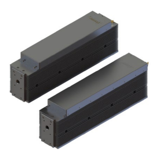
Summary of Contents for Novanta vi30
- Page 1 Laser User Manual ENGINEERED BY SYNRAD...
-
Page 2: Table Of Contents
Terms ....................................... 13 Other hazards ....................................16 Disposal......................................17 Additional laser safety information ..............................18 vi30 Laser label locations ................................. 19 vi40 Laser label locations ................................. 20 Agency Compliance ..................................21 Center for Devices and Radiological Health (CDRH) Requirements ....................21 Federal Communications Commission (FCC) Requirements ...................... - Page 3 Figure 2-3 vi30 Document ................................26 Figure 2-4 vi40 Document ................................27 Figure 3-1 OEM vi30/40 Front panel controls and indicators......................29 Figure 3-2 OEM vi30/40 Rear panel controls and indicators......................30 Figure 4-1 vi30/40 beam ellipticity..............................33...
- Page 4 Table 4-8 vi30/40 General specifications (continued) ........................53 Figure 4-14 OEM vi40 standard package outline and mounting dimensions.................. 54 Figure 4-15 OEM vi30 package outline and mounting dimensions with optional customer-installed ‘Tall/Wide’ mounting feet. 55 Figure 4-16 OEM vi30 package outline and mounting dimensions ....................56 Figure 4-17 OEM vi30 Dual-cooled outline and mounting diagram ....................
-
Page 5: Important Information
Retain these instructions for future reference. Novanta reserves the right to update this user manual at any time without prior notification. If product ownership changes, this manual should accompany the product. DANGER: Indicates a hazardous situation which, if not avoided, will result in serious injury or death. - Page 6 Devices and Radiological Health) certification. Customer Support Before contacting Novanta for assistance, review appropriate sections in the manual that may answer your questions. After consulting this manual, please contact one of our worldwide offices between 9 AM and 5 PM local time.
-
Page 7: Trademark & Copywrite
Warranty Information This is to certify that vi30/40 lasers are guaranteed by NOVANTA to be free of all defects in materials and workmanship for a period of one year from the date of purchase. This warranty does not apply to any defect caused by negligence, misuse (including environmental factors), accident, alteration, or im- proper maintenance. -
Page 8: Sales, Application & Support
Novanta@Novanta.com Sales & Application NOVANTA Regional Sales Managers work with customers to identify and develop the best CO2 laser solution for a given application. Because they are familiar with you and your laser application, use them as a first point of contact when questions arise. Regional Sales Managers also serve as the liaison between you and our Applications Lab in processing material samples per your specifications. -
Page 9: Reference Materials
Operator’s Manuals, Technical Bulletins, and Application Newsletters. Most of these materials are also available directly from the NOVANTA web site at http://www.Novanta.com. EU Headquarters For assistance in Europe, contact NOVANTA® European subsidiary, NOVANTA Europe, at: ©Novanta Distribution (USD) GmbH Parkring 57-59 85748 Garching bei München,... -
Page 10: Guidelines & Content
Mounting bolts – Three each 1/4-20 x 5/8 UNC caps crews are provided for fastening the vi30/40 laser to your mounting surface. Spare Fuse – Two fast-blow vi30 12 A Cooper Bussmann BK/ABC-12-R or RoHS equivalent (novanta P/N... -
Page 11: Figure 1-1 Vi30/40 Ship Kit Contents
GUIDELINES & CONTENT PAGE Figure 1-1 vi30/40 ship kit contents. Table 1-1 vi30/40 ship kit contents Only with fan and water-cooled models Shipping Box Contents vi30/40 Laser Customer Flier Cooling kit DC power cable set (not shown) Mounting Bolts Spare Fuse... -
Page 12: Nomenclature
“F” for fan-cooled units, and “A” for air-cooled lasers (where the customer must provide the proper cooling via fans or blowers). The last letter in the model number indicates the current model version beginning with “B.” For example, the model number FSVi30SAB designates the vi30 laser as a standard OEM, air-cooled version B. -
Page 13: Laser Safety
General & Other Hazards – provides important information about the hazards and unsafe practices that could result in death, severe injury, or product damage. • Disposal – information on your vi30/40 laser parts and/or components as they pertain to disposal. •... - Page 14 TERMS PAGE • Warning: Potential & Imminent hazards which, if not avoided, could result in death or serious injury. Alerts operator of serious dangers, hazardous radiation, hazardous voltages, vapor hazard, & reflective dangers. • Danger: Hazards which, if not avoided, could result in minor or moderate injury. Alerts operator of lifting dangers.
- Page 15 TERMS PAGE Following are descriptions of general hazards and unsafe practices that could result in death, severe injury, or product damage. Specific warnings and cautions not appearing in this section are found throughout the manual. Warning: Serious Personal Injury Enclose the beam path whenever possible. Exposure to direct or diffuse CO2 laser radiation can seriously burn human or animal tissue, which may cause permanent damage.
-
Page 16: Other Hazards
OTHER HAZARDS PAGE noncombustible material as the beam block. Never use organic material or metals as the beam blocker; organic materials, in general, are apt to combust or melt and metals act as specular reflectors which may create a serious hazard outside the immediate work area. Warning: Serious Personal Injury Always wear safety glasses or protective goggles with side shields to reduce the risk of damage to the eyes when operating the laser. -
Page 17: Disposal
Disposal This product contains components that are considered hazardous industrial waste. If a situation occurs where the laser is rendered non-functional and cannot be repaired, it may be returned to NOVANTA ® who, for a fee, will ensure adequate disassembly, recycling and/or disposal of the product. -
Page 18: Additional Laser Safety Information
ADDITIONAL LASER SAFETY INFORMATION PAGE Additional laser safety information The NOVANTA web site https://www.Novanta.com/resources/general_information/lasersafetyresources contain an online laser safety handbook that provides information on (1) Laser Safety Standards for OEM’s/System Integrators, (2) Laser Safety Standards for End Users, (3) References and Sources, and (4) Assistance with Requirements. -
Page 19: Vi30 Laser Label Locations
VI30 LASER LABEL LOCATIONS PAGE vi30 Laser label locations Figure 2-1 vi30 hazard label locations... -
Page 20: Vi40 Laser Label Locations
VI40 LASER LABEL LOCATIONS PAGE vi40 Laser label locations Figure 2-2 vi40 hazard label locations... -
Page 21: Agency Compliance
(Keyswitch or OEM). See the Class 4 safety features, located in the following table, which indicate which features are available on vi30/40 lasers, the type and description of the feature, and if the feature is required by CDRH regulations. -
Page 22: Federal Communications Commission (Fcc) Requirements
Important Note: The following FCC information to the user is provided to comply with the requirements of 47 CFR, Part 18, Section 213. Interference Potential In our testing, NOVANTA has not discovered any significant electrical interference traceable to vi30/40 lasers. System Maintenance Ensure that all exterior covers are properly fastened in position. -
Page 23: European Union (Eu) Requirements Rohs Compliance
Vi30/40 OEM lasers are OEM products intended for incorporation as components in laser processing systems. As supplied by NOVANTA, these lasers do not meet the requirements of EN 60825-1 without additional safeguards. European Union Directives state that “OEM laser products which are sold to other manufacturers for use as components of any system for subsequent sale are not subject to this Standard, since the final product will itself be subject to the Standard.”... - Page 24 EUROPEAN UNION (EU) REQUIREMENTS ROHS COMPLIANCE PAGE vi30/40 lasers have demonstrated performance characteristics that have met or exceeded the requirements of EMC Directive 2004(2014)/108/EC. Table 2-1 Class 4 safety features. Available Required by: Feature Location Description CDRH EN60825-1 vi30/40 On/Off/Reset Key switch controls power to laser electronics.
- Page 25 Not available nor required on vi Series OEM lasers. When integrating NOVANTA vi30 OEM lasers, the Buyer and/or integrator of the end system is responsible for meeting all applicable Standards to obtain the CE mark. To aid this compliance process, NOVANTA testing program has demonstrated that vi30 lasers comply with the relevant requirements of Directive 2014/30/EU, the Electromagnetic Compatibility Directive, as summarized in table below.
-
Page 26: Figure 2-3 Vi30 Document
EUROPEAN UNION (EU) REQUIREMENTS ROHS COMPLIANCE PAGE Figure 2-3 vi30 Document... -
Page 27: Figure 2-4 Vi40 Document
EUROPEAN UNION (EU) REQUIREMENTS ROHS COMPLIANCE PAGE Figure 2-4 vi40 Document... -
Page 28: Operation
Controls and Indicators The controls and indicators section includes subsections. • OEM vi30/40 front panel • OEM vi30/40 rear panel Warning: Serious Personal Injury Any Class 4 CO2 laser product that emits invisible infrared laser radiation in the 9–11 µm wavelength band can seriously burn human tissue. -
Page 29: Figure 3-1 Oem Vi30/40 Front Panel Controls And Indicators
Aperture Seal – prevents dust from damaging laser optics during shipping. Remove the red self- adhesive label before applying power to the laser. Laser Aperture – provides an opening in the vi30/40’s front panel from which the beam exits. Optical Accessories Mounting – provides six threaded holes (8–32 UNC) for mounting optional beam delivery components. -
Page 30: Figure 3-2 Oem Vi30/40 Rear Panel Controls And Indicators
DC Power Cables – receives +48 VDC from the DC power supply. The DC power cables are manufactured from #12 AWG wire and measure 1 meter (42 inches) in length. The red (positive) cable contains a replaceable in-line fuse. If vi30/40 fuse replacement is required, refer to the Getting Started section of this manual. -
Page 31: Technical Reference
TECHNICAL REFERENCE PAGE • Important note: To prevent damage when mounting optical components to the OEM vi30 laser, the 8–32 UNC fasteners must extend no further than 4.8 mm (0.19”) into the laser’s faceplate. Technical reference Use information in this section as a technical reference for your laser This section contains the following information: •... -
Page 32: Oem Vi30/40 Design
The optical resonator, in conjunction with the electrodes and the gas mixture, generates the laser beam. vi30/40 optical resonators are comprised of four optical elements: a rear mirror, two turning mirrors, and an output window. These optical elements are fastened to the tube’s exterior and are exposed to its interior through holes in the end caps. -
Page 33: Optical Setup
Figure 4-1 vi30/40 beam ellipticity. Internal RF power supply OEM vi30/40 lasers are driven by a compact radio frequency (RF) oscillator mounted in the laser chassis. The 48 VDC input voltage is converted into a high-power RF signal using an RF power oscillator. - Page 34 OPTICAL SETUP PAGE Expander/collimators are optical devices that increase beam diameter by a selectable magnification factor while reducing beam divergence at the same time. Adding an expander/collimator reduces beam divergence and any variance in beam diameter caused by the changing optical path length in an XY (“flying optics”) table application.
-
Page 35: Figure4.2Recommended Fan Shroud Example
NOVANTA recommends using two cooling fans rated for at least 4.0 m3/min (140 CFM) for the vi30, or 5.4m3/min (190) for the vi40. The cooling fans should measure 120 × 120 mm (4.7” × 4.7”) and have at least 57.2 mm (2.25”) of... - Page 36 Position both fans so the front face is no more than 76mm (3.0”) from the vi30/40’s heat-sink fins. When using a tight-fitting fan shroud designed for side cooling, the cooling fans can be positioned within 5–25 mm (0.20–1.0”) of the heatsink fins as long as the same gap is maintained on either side.
- Page 37 OPTICAL SETUP PAGE when the system is shut down, but coolant continues to flow through the laser for extended periods of time. The chiller’s temperature set-point must always be set above the dew point temperature. In cases where this is not possible within the specified coolant temperature range of 18 °C to 22 °C (64 °F to 72 °F), then the following steps MUST be taken to reduce the risk of condensation damage.
- Page 38 OPTICAL SETUP PAGE Table 4-2 Dew Point Table °F temperatures. Dew Point Table °F...
-
Page 39: Controlling Laser Power
Much of the information provided in this section describes the use of a NOVANTA UC-2000 Universal Laser Controller to provide tickle and PWM Command signals to the vi30/40 laser. If using an alternate method of laser control, thoroughly review this section, controlling laser power, as well as the following... -
Page 40: Operating Modes
PWM input signals if the “On” pulse is less than 100 μs in duration. At a constant 50% duty cycle, vi30/40 lasers typically reach 90–100% of full optical output when operated at a frequency of 5 kHz and reach 65–80% optical output at 7 kHz. The percentage of optical output increases as duty cycle increases (at a constant PWM frequency) or as PWM frequency decreases (at a constant duty cycle). -
Page 41: Figure 4-3 Typical Optical Output Pulse (50%) Duty Cycle At 3Khz
OPERATING MODES PAGE Figure 4-3 Typical optical output pulse (50%) duty cycle at 3kHz. Figure 4-4 Typical optical output pulse (50%) duty cycle at 5kHz. Warning: Serious Personal Injury Always use shielded cable when connecting your PWM Command signal source to PWM Positive/PWM Negative inputs. -
Page 42: Figure 4-5 Pwm Command Signal Waveform
Figure 4-5 PWM Command signal waveform The vi30/40’s DB-9 I/O PWM input consists of a high-speed optoisolator LED with a forward voltage drop (Vf) of 1.5 VDC. The PWM input frequency can range from DC (0 Hz) to 100 kHz. The following... - Page 43 The vi30/40’s DB-9 I/O PWM input consists of a high-speed optoisolator LED with a forward voltage drop (Vf) of 1.5 VDC. The PWM input frequency can range from DC (0 Hz) to 100 kHz. The prior PWM command signal level table provides minimum, maximum, and nominal PWM signal specifications.
- Page 44 OPERATING MODES PAGE Continuous wave (CW) In some applications, such as high-speed marking or cutting, the time constant of the laser and the PWM modulation causes a series of dots that may be visible on the marking surface instead of a “clean” line. Operating the laser in CW mode will prevent this behavior from occurring.
-
Page 45: User I/O Connection Summary
User outputs indicate vi30/40 ready, lase, overtempt, and input voltage status. The OEM vi30/40’s PWM inputs are optoisolated; however, all other inputs and outputs operate using standard 5V logic levels (0V – logic low; 5V – logic high). Both inputs and outputs are ESD protected but are not optoisolated;... - Page 46 (LASE indicator Off). The Lase Indicator output sources 20 mA typical, 40 mA maximum. On the vi30 laser, this output goes logic high (+5V) when an over Overtemp Fault temperature fault condition is detected, causing the RDY indicator to flash Output (vi30) continuously.
-
Page 47: Figure 4-7 Input Equivalent Schematic
On state Vmin +2.0 VDC @ 0.2 mA On state (continuous) Vmax +5.0 VDC @ 0.5 mA Important Note: Do not apply a Laser Enable signal until the OEM vi30/40’s internal +5 VDC power supply has stabilized (approximately 200 ms after DC power-up). -
Page 48: Sample Input Circuit
DB-9 I/O Connections The figure below illustrates one method of applying the Laser Enable signal using a customer-supplied limit switch or relay contact powered by the OEM vi30/40’s DC Out output (+5 V, 250 mA). DB-9 I/O PINS Figure 4-8 OEM vi30/40 powered Laser Enable circuit. -
Page 49: Figure 4-10 Plc Switched Laser Enable Circuit
DC supply voltage is within limits. The vi30/40 also includes a +5 VDC output voltage source, DC Out. This output can provide a maximum current of 250 mA and is useful for driving the Laser Enable input as described in the Input circuitry subsection. -
Page 50: Figure 4-11 Output Equivalent Schematic
SAMPLE INPUT CIRCUIT PAGE Laser Enable On state Vmin +4.5 VDC @ 50 mA Over-temp Fault On state (typical) +5.0 VDC @ 0.5 mA DC voltage Fault Off state Vmax +0.8 VDC Table 4-7 DB-9 output circuit specifications Figure 4-11 Output equivalent schematic. -
Page 51: Sample Output Circuit
PAGE Sample output circuit You can monitor OEM vi30/40 laser status remotely by connecting one or more outputs to an isolated 5 VDC solid state relay or PLC input module. The figure below illustrates the connections required to monitor the vi30’s Lase Indicator status, or any other vi30 output, using an isolated 5 VDC input module. -
Page 52: Vi30/40 General Specifications
VI30/40 GENERAL SPECIFICATIONS PAGE Vi30/40 General Specifications Table 4-8 vi30/40 General specifications. -
Page 53: General Specifications (Continued)
GENERAL SPECIFICATIONS (CONTINUED) PAGE General Specifications (Continued) Table 4-8 vi30/40 General specifications (continued) * Specifications subject to change without notice. 1 This power level is guaranteed for 12 months regardless of operating hours. 2 48 VDC input voltage to obtain guaranteed output power. -
Page 54: O&M Drawings
O&M DRAWINGS PAGE O&M Drawings Figure 4-14 OEM vi40 standard package outline and mounting dimensions. -
Page 55: Figure 4-15 Oem Vi30 Package Outline And Mounting Dimensions With Optional Customer-Installed 'Tall/Wide' Mounting Feet
O&M DRAWINGS PAGE Figure 4-15 OEM vi30 package outline and mounting dimensions with optional customer-installed ‘Tall/Wide’ mounting feet. -
Page 56: Figure 4-16 Oem Vi30 Package Outline And Mounting Dimensions
O&M DRAWINGS PAGE Figure 4-16 OEM vi30 package outline and mounting dimensions... -
Page 57: Figure 4-17 Oem Vi30 Dual-Cooled Outline And Mounting Diagram
O&M DRAWINGS PAGE With optional customer-installed ‘Tall’ mounting feet. Figure 4-17 OEM vi30 Dual-cooled outline and mounting diagram... -
Page 58: Figure 4-18 Oem Vi40 Dual-Cooled Outline And Mounting Diagram
O&M DRAWINGS PAGE Figure 4-18 OEM vi40 Dual-cooled outline and mounting diagram. -
Page 59: Figure 4-19 Oem Vi30/40 Packaging Instructions
O&M DRAWINGS PAGE Figure 4-19 OEM vi30/40 packaging instructions. -
Page 60: Maintenance & Troubleshooting
• Cleaning optical components Disabling the vi30/40 laser Before performing any maintenance on your OEM vi30/40 laser, be sure to completely disable the laser by disconnecting the DC Power Cables from the DC power supply. Daily inspections Perform the following steps daily to keep your vi30/40 laser in optimum operating condition. Except for the procedures described below, no other service is required or should be attempted. -
Page 61: Cooling
NOVANTA recommends using two cooling fans rated for at least 4.0 m3/min (140 CFM) for the vi30 at a static air pressure of 13.9 mm H2O (0.52 in H2O). The cooling fans should measure 120 × 120 mm (4.7” × 4.7”) and have at least 57.2 mm (2.25”) of unobstructed clearance between the rear face of the fan housing and any mounting surface or... - Page 62 COOLING PAGE Cleaning optical components Debris or contaminants on external beam delivery components may affect laser processing and lead to damage or failure of the optics and/or the laser. Carefully follow the steps below to inspect and clean the optical components in the beam path. Before beginning the cleaning process, read this entire section thoroughly to ensure that all cleaning materials are available and that each step is completely understood.
- Page 63 COOLING PAGE Table 5-1 Required cleaning materials. Caution: Possible Equipment Damage Do not allow the nozzle of the air bulb to touch the optical surface. Any contact may damage the optic by scratching coatings on the optical surface. Do not use compressed shop air to blow contamination from the optic. Compressed air contains significant amounts of water and oil that form adsorbing films on the optical surface.
-
Page 64: Troubleshooting
Status LEDs Three status LEDs on the rear of the OEM vi30 laser provide a visual indication of operating status. A green PWR LED illuminates when DC power is applied to the laser. The yellow RDY LED indicates that a Laser Enable signal has been applied and that, after a five-second delay, lasing will begin once a PWM Command signal is received. -
Page 65: Operational Flowchart
OPERATIONAL FLOWCHART PAGE Operational flowchart Figure 5-1 vi30/40 operational flowchart. -
Page 66: Status Leds
STATUS LEDS PAGE Status LEDs Table 5-2 vi30/40 Input I/O status states. -
Page 67: Resetting Faults
Laser fault indications OEM vi30/40 lasers can indicate five specific fault conditions. In the event of certain faults, the RDY LED, PWR LED or both will blink an error code, pause 1/2 second, and then repeat the code. This sequence continues until the fault is corrected and the laser is reset by cycling DC power to the laser. -
Page 68: Beam Delivery Optics
NOVANTA or a NOVANTA Authorized Distributor. PWM Sense/Control Board fault A PWM Sense or control board fault is indicated by both RDY and PWR indicators flashing continuously. If this fault occurs, the laser requires service—contact NOVANTA or a NOVANTA Authorized Distributor. Symptom: •... - Page 69 BEAM DELIVERY OPTICS PAGE This page is left blank intentionally...
-
Page 70: Index
INDEX PAGE Index European headquarters, 8 Symbols Control signals 39–41 +24 VDC 45, 46, 48 Copyright information 6 Customer Service 8 Aperture American National Standards Institute (ANSI) 17 Daily inspections 62 see Laser aperture Danger Assist gas purity eye protection, 14, 61 specifications, 33, 35, 40, 41 laser radiation, 14, 15, 16, 31, 61 Auxiliary DC power... - Page 71 INDEX PAGE sample diagrams, 48 output equivalent schematic, 50 specifications, 47 specifications, 49, 52, 53 Input signals customer-supplied interlock, negative voltage, PWM Input signal 41, 43 PWM Return, 45 specifications, 47 Inspections PWM Return signal 41, 43, 45 daily, 62 Quick Start Plug Label locations 19, 20 wiring diagram, 49...
- Page 72 INDEX PAGE UC-2000 Laser Controller 43 Warning air contaminants, 5, 40, 44 eye protection, 14, 61 laser radiation, 64, 71, 72 Warranty information 7...
- Page 73 INDEX PAGE This page is intentionally left blank...
- Page 74 Engineered by Synrad, part of Novanta © 2022, Novanta Corporation. All rights reserved. Novanta Headquarters, Bedford, USA Phone: +1-781-266-5700 Email: photonics@novanta.com ###### Revision X August 2022...
Need help?
Do you have a question about the vi30 and is the answer not in the manual?
Questions and answers