Table of Contents
Advertisement
Quick Links
MP124E
V-273 VC Linear Actuator
User Manual
Version: 1.0.0
Date: 30.03.2015
This document describes the following
products:
V-273.430
PIMag® Voice Coil Linear Actuator,
20 mm, 6 N, Linear Encoder,
0.1 µm Resolution
V-273.431
PIMag® Voice Coil Linear Actuator,
20 mm, 6 N, Linear Encoder,
0.1 µm Resolution, Force Sensor
Physik Instrumente (PI) GmbH & Co. KG, Auf der Roemerstr. 1, 76228 Karlsruhe, Germany
Phone: +49 721 4846-0, Fax: +49 721 4846-1019, E-mail: info@pi.ws
Advertisement
Table of Contents

Related Manuals for PI V-273


Summary of Contents for PI V-273
- Page 1 PIMag® Voice Coil Linear Actuator, 20 mm, 6 N, Linear Encoder, 0.1 µm Resolution, Force Sensor Physik Instrumente (PI) GmbH & Co. KG, Auf der Roemerstr. 1, 76228 Karlsruhe, Germany Phone: +49 721 4846-0, Fax: +49 721 4846-1019, E-mail: info@pi.ws...
- Page 2 With regard thereto, Physik Instrumente (PI) GmbH & Co. KG retains all the rights. Use of said text, photographs and drawings is permitted only in part and only upon citation of the source.
-
Page 3: Table Of Contents
Contents About this Document Goal and Target Audience of this User Manual ........... 1 Symbols and Typographic Conventions ............... 1 Definition ....................... 2 Figures ........................3 Other Applicable Documents ................3 Downloading Manuals ..................3 Safety Intended Use ......................5 General Safety Instructions .................. - Page 4 Installing the V-273 in a Mechanical Mounting ...........17 Connecting the Motor Cable to the V-273 ............20 Start-Up and Operation General Notes on Start-Up and Operation ............21 Starting Up the V-273 with the C-413 Controller ..........24 Maintenance General Notes on Maintenance ................27 Cleaning the V-273 .....................27...
-
Page 5: About This Document
Downloading Manuals ....................3 1.1 Goal and Target Audience of this User Manual This manual contains information on the intended use of the V-273. It assumes that the reader has a fundamental understanding of basic servo systems as well as motion control concepts and applicable safety procedures. -
Page 6: Definition
The feed is generated by the Lorentz force on an energized coil (PIMag® principle) that couples to a moving rod. The V-273 thus combines a relatively long travel range with a high velocity and a high resolution. Max. push/pull force Maximum force in the direction of motion. -
Page 7: Figures
Document C-413 PIMag® Controller MS224E User Manual PIMikroMove SM148E Software Manual 1.6 Downloading Manuals INFORMATION If a manual is missing or problems occur with downloading: Contact our customer service department (p. 31). V-273 VC Linear Actuator MP124E Version: 1.0.0... - Page 8 4. Find the user name and the password in the section "User login for software download" in the Release News. 5. Open the FTP download directory (ftp://pi-ftp.ws). − Windows operating systems: Open the FTP download directory in Windows Explorer.
-
Page 9: Safety
The V-273 is built according to state-of-the-art technology and recognized safety standards. Improper use can result in personal injury and/or damage to the V-273. Only use the V-273 for its intended purpose, and only use it if it is in a good working order. -
Page 10: Organizational Measures
Add all information given by the manufacturer to the user manual, for example supplements or Technical Notes. If you pass the V-273 on to other users, also turn over this user manual as well as other relevant information provided by the manufacturer. -
Page 11: Product Description
Scope of Delivery ......................10 Suitable Controllers ..................... 11 Technical Features ...................... 11 3.1 Model Overview Two standard versions of the V-273 linear actuator are available. They differ with regard to the force sensor and thus the dimensions. Model Dimension Force sensor present? V-273.430... -
Page 12: Product Details
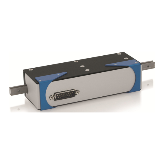
3 Product Description 3.2.2 Product Details Figure 2: Front side of the V-273.430 linear actuator Moving rod (= guide rail) Case Connection for motor cable (panel plug, Sub-D 15) Positive direction of motion Figure 3: Front side of the V-273.431 linear actuator... -
Page 13: Product Labeling
Figure 4: Force sensor of the V-273.431 model M3 threaded bolt for screwing the contact piece onto the force sensor Figure 5: Rear side of the V-273 linear actuator, hole pattern and transport lock are identical for both standard versions Case Transport lock (M2.5 screw) -
Page 14: Scope Of Delivery
Linear actuator according to order (p. 7) V-273.431 000025499 M2.5x12 A2 screw ISO 14580 as transport lock C-815.18 Sub-D 15 (m/f) motor cable, 1 m MP124E User manual (this document) in printed form Version: 1.0.0 MP124E V-273 VC Linear Actuator... -
Page 15: Suitable Controllers
3.5 Technical Features 3.5.1 Linear Encoder The V-273 is equipped with an optical linear encoder. For the resolution, refer to the table in the "Specifications" section (p. 33). Optical linear encoders measure the actual position directly (direct metrology). -
Page 16: Force Sensor
0 N, regardless of the actual force exerted on the force sensor. 3.5.4 ID Chip The V-273 linear actuators contain one ID chip per sensor on which the following data is stored: ... - Page 17 Only ship the V-273 in the original packaging and with a transport lock installed. Only hold the V-273 by the housing The V-273 is delivered with a transport lock installed. Figure 6: Rear side of the V-273 linear actuator, hole pattern and transport lock are identical for both standard versions Case Transport lock (M2.5 screw)
- Page 18 1. Unpack the V-273 with care. 2. Compare the contents against the items covered by the contract and against the packing list. If parts are incorrectly supplied or missing, contact PI immediately. 3. Inspect the contents for signs of damage. If you notice signs of damage, contact PI immediately.
-
Page 19: Installation
Install the V-273 so that the application is not affected by the dissipated heat. Ensure sufficient ventilation at the place of installation. Make sure that the complete bottom side of the V-273 is in contact with the surface on which the V-273 is mounted. -
Page 20: Optional: Changing The Contact Piece Of The Force Sensor On The V-273.431 Model
The linear actuator is not connected to the controller. Tools and accessories Suitable contact piece with M3 internal thread Changing the contact piece of the force sensor on the V-273.431 model: 1. Manually unscrew the contact piece to be replaced from the force sensor of the V-273.431. -
Page 21: Installing The V-273 In A Mechanical Mounting
NOTICE Damage and reduced performance due to torque at the rod! An excessive torque at the rod of the V-273 can damage the drive or reduce the performance of the drive. Make sure that the rod can be easily moved over the entire travel range. - Page 22 Figure 7: V-273.430: The white arrows mark the holes for affixing the movable part of the mounting to the Figure 8: V-273.430: Mounting holes for attaching the V-273 to a surface, identical for V-273.431 Figure 9: V-273.431: The contact piece of the force sensor ideally has an orthogonal orientation to the...
- Page 23 Tools and accessories If the movable part of the mechanical mounting is to be connected to the moving rod of the V-273.430: 1 to 2 M2 screws of suitable length (see "Dimensions" (p. 37)) 3 to 5 M4 screws of suitable length (see "Dimensions" (p. 37)) for attaching...
-
Page 24: Connecting The Motor Cable To The V-273
1. Align the moving rod of the linear actuator in the mounting so that the corresponding mounting holes in mounting and rod overlap. 2. Affix the movable part of the mounting to the holes in the rod of the V-273. 3. Check that the connected parts fit without backlash. -
Page 25: Start-Up And Operation
Starting Up the V-273 with the C-413 Controller ............24 6.1 General Notes on Start-Up and Operation The start-up of the V-273 is done with the PIMag® C-413 motion controller from PI. NOTICE Heating up of the V-273 during operation! The heat produced during operation of the V-273 can affect your application. - Page 26 NOTICE Undesired displacement due to lack of self-locking! The drive of the V-273 does not have any self-locking. Switching off or rebooting the controller or switching off the servo mode for the axis can therefore lead to undesired displacements of the moving rod, e.g. due to the weight force of the moving mass.
- Page 27 INFORMATION The C-413 controller and the V-273 are delivered as a preconfigured system. If a connection assignment is given on the labels of the controller and/or V-273, observe this assignment when connecting the V-273. V-273 VC Linear Actuator MP124E Version: 1.0.0...
-
Page 28: Starting Up The V-273 With The C-413 Controller
AutoZeroResult parameter (ID 0x07000A03) when the servo mode is switched off. When an AutoZero procedure has been successfully performed, the parameter value is set so that the V-273 compensates for the weight force of the moving mass with the corresponding control value (important with a vertically aligned motion axis). - Page 29 Motor cable connected to the Motor & Sensor 1 socket and - if present - force sensor connected to the Motor & Sensor 2 socket: V-273 is commanded as axis 1; the force sensor can be read out as input signal channel 3 and must be assigned to axis 1 via the Input Channel for Force Feedback parameter (ID 0x07000400).
- Page 30 6 Start-Up and Operation − Commanding initial motions in closed-loop operation for testing the mechanical system In the user manual of the C-413 controller, the start-up is described using the PIMikroMove program. Version: 1.0.0 MP124E V-273 VC Linear Actuator...
-
Page 31: Maintenance
7.1 General Notes on Maintenance NOTICE Damage from opening the V-273! The V-273 is maintenance-free. Opening the case causes damage to the V-273. Only loosen screws according to the instructions in this manual. Do not open the V-273. -
Page 33: Troubleshooting
If necessary, correct the settings of the improperly Uncontrolled servo-control parameters. oscillation of the V-273 Mount the V-273 on an even surface. The Increased wear Warped case recommended evenness of the surface is Reduced accuracy Excessive lateral forces 20 µm. -
Page 35: Customer Service
9 Customer Service Customer Service For inquiries and orders, contact your PI sales engineer or send us an e-mail (info@pi.ws). If you have questions concerning your system, have the following information ready: Product codes and serial numbers of all products in the system ... -
Page 37: Technical Data
Straightness of travel ±20 µm ±5 % Velocity, open-loop mm/s max. Velocity, closed-loop mm/s max. Mechanical properties Bearing / guiding Linear guiding Moved mass without load 56 (186 with force typ. sensor) V-273 VC Linear Actuator MP124E Version: 1.0.0... - Page 38 Sub-D 15 (m); with force sensor: 2 × Sub-D 15 (m) Lifetime >10 cycles min. Recommended controller C-413 * With C-413 controller. ** Allowable average value for continuous operation, not to be exceeded. Version: 1.0.0 MP124E V-273 VC Linear Actuator...
-
Page 39: Maximum Ratings
10 Technical Data 10.1.2 Maximum Ratings The voice coil drive of the V-273 linear actuator is designed for the following operating data: Maximum Maximum Operating Maximum Power Operating Voltage Frequency Consumption 48 V 24 W 10.1.3 Ambient Conditions and Classifications... -
Page 40: Reference Point Switch Specifications
Direction sensing by means of different signal levels on the left and right side of the reference point switch: The signal level changes from 0 to +5 V when the reference point switch is passed. Version: 1.0.0 MP124E V-273 VC Linear Actuator... -
Page 41: Dimensions
10 Technical Data 10.2 Dimensions 10.2.1 V-273.430 Dimensions in mm. Note that the decimal places are separated by a comma in the drawings. Figure 10: Dimensions of the V-273.430, moving rod in reference position V-273 VC Linear Actuator MP124E Version: 1.0.0... - Page 42 10.2.2 V-273.431 Dimensions in mm. Note that the decimal places are separated by a comma in the drawings. Figure 11: Dimensions of the V-273.431, here without contact piece of the force sensor; moving rod in reference position. M3 external thread A shows the ideal direction of a force that acts on the force sensor.
- Page 43 10 Technical Data Figure 12: Dimensions of the V-273.431, here with contact piece of the force sensor; moving rod in reference position. V-273 VC Linear Actuator MP124E Version: 1.0.0...
-
Page 44: Pin Assignment
TTL input SPI_MISO TTL output Motor (+) Input current AGND AGND Reference TTL output SPI_CLK TTL input SPI_CS_SENSOR TTL input * The "-" sign indicates that the corresponding pin has not been assigned. Version: 1.0.0 MP124E V-273 VC Linear Actuator... -
Page 45: V-273.431: Connection Of The Force Sensor
10 Technical Data 10.3.2 V-273.431: Connection of the Force Sensor Sub-D 15 (m) connector Figure 14: Sub-D 15 (m) connector Function* Direction VDD, + 5 V Input SPI_CS_EEPROM TTL input SPI_MOSI TTL input SPI_MISO TTL output SPI_CLK TTL input SPI_CS_SENSOR TTL input * The "-"... -
Page 47: Old Equipment Disposal
Instrumente (PI) GmbH & Co. KG ensures environmentally correct disposal of old PI equipment that was first put into circulation after 13 August 2005, free of charge. If you have old PI equipment, you can send it postage-free to the following address: Physik Instrumente (PI) GmbH & Co. KG Auf der Römerstr. - Page 49 12 EC Declaration of Conformity 12 EC Declaration of Conformity For the V-273, an EC Declaration of Conformity has been issued in accordance with the following European directives: 2004/108/EC, EMC Directive 2011/65/EU, RoHS Directive The applied standards certifying the conformity are listed below.
Need help?
Do you have a question about the V-273 and is the answer not in the manual?
Questions and answers