Table of Contents
Advertisement
Quick Links
Advertisement
Table of Contents

Related Manuals for Pulsar PG6580ECO


Summary of Contents for Pulsar PG6580ECO
- Page 1 Model: PG6580ECO Generator OPERATOR’S MANUAL support@pulsar-products.com...
-
Page 2: Table Of Contents
TABLE OF CONTENTS Introduction....................................Product Specifications..............................Parts Ordering / Customer Service..........................Safety Rules..................................... Safety Symbols................................Safety Instructions ..............................Features....................................Assembly....................................Unpacking ..................................Packing List ................................. Attaching Wheels................................Attaching Battery Cable..............................Adding Oil..................................Adding Fuel.................................. Connecting Generator to an Electrical System......................Operation.................................... -
Page 3: Introduction
INTRODUCTION Thank you for purchasing this superior quality portable generator from Pulsar Products Inc. When operating and maintaining this product as instructed in this manual, your generator will give you many years of reliable service. Product Specifications: This generator is an engine-driven, revolving field, alternating current (AC) portable generator. It is designed to supply electrical power to operate tools, appliances, camping equipment, lighting, or serve as a back up power source during power outages. -
Page 4: Safety Rules
SAFETY RULES Safety Symbols Indicates a potentially hazardous situation which could result in serious injury or death if not WARNING! avoided. Indicates a potentially hazardous situation which could result in damage to equipment or CAUTION! property. Toxic Fumes Risk of fire Risk of explosion Risk of electric shock Hot surface... - Page 5 SAFETY RULES Never exceed generator’s wattage / amperage capacity. This could damage the generator WARNING! and / or connected electrical devices. Check operating voltage and frequency requirements of all electrical devices prior to plugging them into the generator. • Never start or stop engine with electrical devices plugged in to the receptacles. Failure to do WARNING! so could damage the generator and / or connected electrical devices.
- Page 6 Never transport or make adjustments to this unit while it is running. • Never insert objects through cooling slots. Never operate this unit if there are any broken or missing parts and only use Pulsar WARNING! replacement parts specifically designed for this unit.
-
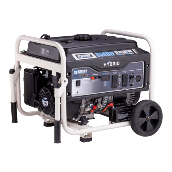
Page 7: Features
FEATURES A - ON/OFF/Start Switch F - Grounding Connection B - 3 IN 1 Meter G - Four 120v GFCI outlets NEMA 5-20R C - Main breaker H - 12V DC Output D - Circuit Protectors I - Oil Alert Lamp E - 120V / 240V 30 Amp Twist Lock (L14-30) J - Co Sensor Light... - Page 8 FEATURES Q - Recoil Pull Starter K - Fuel Tank L - Fuel Tank Vapor Vent R - Handle S - Support Foot M - Frame N- Choke Lever T - Oil Fill and Dipstick O -Fuel Valve (ON/OFF) U - Battery V - No Flat Tires P - Air Filter...
-
Page 9: Assembly
ASSEMBLY Unpacking 1. Place box on a level surface. 2. Remove all items from box except the generator. Make sure all items listed on the packing list are included and not damaged. 3. Cut down the sides of the box being careful to avoid hitting the generator. 4. -
Page 10: Attaching Wheels
ASSEMBLY Attaching Wheels (See fig 1) • Parts needed - 2 wheels, 2 axles, 2 hair pins, and 2 washers. • Raise or tilt generator so you can slide the wheel axle pin into the wheel, the washer, the wheel mounting hole located on the side of the frame. -
Page 11: Attaching Battery Cable
ASSEMBLY Attaching Battery Cable (See fig 3) • Locate the pigtail harness already attached to the battery (-) negative post • Ensure the hardware is tight and the red rubber boot is fitted over the (+) battery • connection Align the male and female battery cable connectors and firmly fit them together Be careful not to short across the terminals when installing. -
Page 12: Adding Oil
ASSEMBLY Antidotes for battery acid CONTACT TREATMENT External Flush with water. Internal Drink large quantities of milk or water, followed by milk of magnesia, vegetable oil or beaten eggs. Get immediate medical attention. Eyes Flush with water. Get immediate medical attention. Adding / Checking Engine Oil (See fig 4) •... -
Page 13: Adding Fuel
ASSEMBLY Adding Fuel (See fig 5) • Set generator outdoors that is well ventilated. • Remove fuel cap. • Insert a funnel into the fuel tank and carefully pour gasoline into the tank until fuel level reaches 1 ½ inches below the top of the neck. -
Page 14: Operation
OPERATION Grounding the Generator (See fig 6) The ground terminal located on the front panel of the generator may be used for additional grounding, or when connected to a structure. Connect the ground terminal to an earthen ground rod, driven six feet into the ground. with a No 8 AWG (American Wire Gauge) copper wire. - Page 15 OPERATION CHOKE CHOKE LEVER Fig 7 Fig 8 SKIP THIS IF THE ENGINE IS WARM OR HOT START START Fig 9 Electric Start Fig 10 Recoil Start WAIT 5sec CHOKE CHOKE LEVER Fig 11 Battery Charger (Not Included) for Electric Starter Keep the generator battery fully charged and ready to use to avoid the need to use the recoil starter to start the generator manually.
-
Page 16: How To Stop Engine
OPERATION How to Stop Engine (See fig 12-14) All loads MUST be disconnected from the generator. Never start or stop the engine with electrical devices plugged in to • the receptacles. • Turn the engine START/ON/OFF switch to the “OFF” position. •... -
Page 17: Don't Overload Generator
OPERATION Extension Cord Selection Refer to the below table to ensure the extension cord used has the capacity to carry the required load. If the size of the cable is inadequate it can cause a voltage drop, which can damage the electrical device and cord. Current Load (Watts) Maximum Cord Length... -
Page 18: Wattage Reference Guide
OPERATION Operating voltage and frequency requirement of all electronic equipment should be checked prior to plugging them into this generator. Damage may result if the equipment is not designed to operate within a +/- 10% voltage variation, and +/- 3 Hz frequency variation from the generator name plate ratings. -
Page 19: Charging A 12 Volt Battery
OPERATION Hour Meter (See Fig 15) The digital hour meter operates whenever the engine is running and keeps track of how many hours the unit has been used. Use this meter along with the manual to determine when and what type of service on the unit is needed. The display will show the word “P25”... -
Page 20: Maintenance
Every 2 years (Replace if necessary) (2) * Replace the paper filter element only. Service more frequently when used in dusty areas. These items should be serviced by your PULSAR servicing dealer. Failure to follow this maintenance schedule could result in non-warrantable failures. -
Page 21: Changing Oil
MAINTENANCE Changing Oil (See Fig 17) • Run the generator until the engine is warm. • Place generator on a level surface. • Remove the dipstick. • Place an oil pan underneath the oil drain bolt to collect used oil. •... - Page 22 Spark Arrestor (See Fig 20 If Applicable) • Inspect the spark arrestor for breaks or holes. Replace if necessary. To purchase a replacement spark arrestor contact PULSAR customer service. • Use a brush to remove carbon deposits from the spark arrestor screen as needed.
-
Page 23: How To Store
MAINTENANCE Draining the fuel tank • Turn the engine OFF. • Turn the fuel valve to the OFF position. • Remove the entire air cleaner housing and set it aside for clear access. • If needed, install a fuel hose that will extend to a suitable fuel container large enough to catch the fuel being drained from the tank. -
Page 24: Troubleshooting
TROUBLESHOOTING Problem Cause Solution Engine is running, but AC output is not 1. Open circuit breaker 1. Reset circuit breaker available 2. Poor connection 2. Check and repair 3. Defective cord set 3. Check and repair 4. Connected device is faulty 4. - Page 25 The YELLOW light will flash for at least five minutes after a fault. The generator can be re-started, but may continue to shutoff. A CO sensor fault can only be diagnosed and repaired by an authorized Pulsar service center.
-
Page 26: Diagrams
DIAGRAMS...
Need help?
Do you have a question about the PG6580ECO and is the answer not in the manual?
Questions and answers