Table of Contents
Advertisement
Advertisement
Table of Contents

Related Manuals for Pulsar PG6000R


Summary of Contents for Pulsar PG6000R
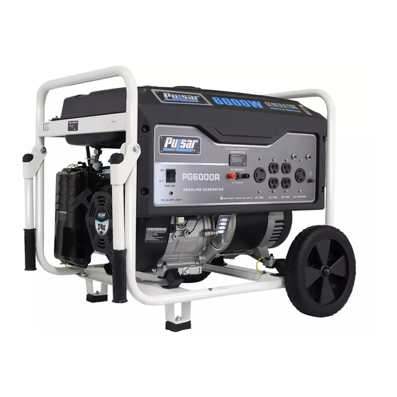
- Page 1 Model: PG6000R Generator OPERATOR’S MANUAL www.pulsar-products.com...
-
Page 2: Table Of Contents
TABLE OF CONTENTS Introduction....................................3 Product Specifications..............................3 Parts Ordering / Customer Service..........................3 Safety Rules.....................................4 Safety Symbols................................4 Safety Instructions ..............................4 Features....................................7 Assembly....................................9 Unpacking ..................................9 Packing List .................................9 Attaching Wheels................................10 Adding Oil...................................11 Adding Fuel................................12 Connecting Generator to an Electrical System......................12 Operation....................................13 Grounding the Generator ............................13 How to Start Engine..............................13 How to Stop Engine..............................15 Receptacles and Extension Cords..........................15... -
Page 3: Introduction
INTRODUCTION Thank you for purchasing this superior quality portable generator from Pulsar Products Inc. When operating and maintaining this product as instructed in this manual, your generator will give you many years of reliable service. Product Specifications: This generator is an engine-driven, revolving field, alternating current (AC) portable generator. It is designed to supply electrical power to operate tools, appliances, camping equipment, lighting, or serve as a back up power source during power outages. -
Page 4: Safety Rules
SAFETY RULES Safety Symbols Indicates a potentially hazardous WARNING! situation which could result in serious injury or death if not avoided. Indicates a potentially hazardous CAUTION! situation which could result in damage to equipment or property. Toxic Fumes Risk of fire Risk of explosion Risk of electric shock Hot surface... - Page 5 SAFETY RULES Never exceed generator’s wattage / amperage capacity. This could damage the generator WARNING! and / or connected electrical devices. Check operating voltage and frequency requirements of all electrical devices prior to plugging them into the generator. • Never start or stop engine with electrical devices plugged in to the receptacles. Failure to do WARNING! so could damage the generator and / or connected electrical devices.
- Page 6 Never transport or make adjustments to this unit while it is running. • Never insert objects through cooling slots. Never operate this unit if there are any broken or missing parts and only use Pulsar WARNING! replacement parts specifically designed for this unit.
-
Page 7: Features
FEATURES A - ON/OFF Start Switch E - Circuit Protectors B - Hour Meter F - 120V / 240V 30 Amp Twist Lock (L14-30) G - Grounding Connection C - 4-120V Receptacles H - Oil Alert D - 120V 30 Amp Twist Lock (L5 -30) I- 12V DC Output (For Charging Batteries Only) - Page 8 FEATURES J - Fuel Tank Vapor Vent Q - Oil Fill and Dipstick K - Choke Lever R - No Flat Tires L - Fuel Valve (ON/OFF) S - Fuel Tank M - Handle N - Recoil Starter Grip O - Air Filter P - Support Foot...
-
Page 9: Assembly
ASSEMBLY Unpacking 1. Place box on a level surface. 2. Remove all items from box except the generator. Make sure all items listed on the packing list are included and not damaged. 3. Cut down the sides of the box being careful to avoid hitting the generator. 4. -
Page 10: Attaching Wheels
ASSEMBLY Attaching Wheels (See fig 1) • Parts needed - 2 wheels, 2 axles, 2 hair pins, and 2 washers. • Raise or tilt generator so you can slide the wheel axle pin into the wheel, the washer, the wheel mounting hole located on the side of the frame. -
Page 11: Adding Oil
ASSEMBLY Adding / Checking Engine Oil (See fig 3) • Place generator on a level surface. • Remove the crankcase dipstick to ensure you do not overfill the engine. • Insert a funnel into the crankcase dipstick hold and carefully add 4-Cycle engine oil (SAE10W- 30) to empty reservoir until oil reaches the outer edge of the oil fill hole (crankcase dipstick hole). -
Page 12: Adding Fuel
ASSEMBLY Adding Fuel (See fig 4) • Set generator on a clean and level surface in an area that is well ventilated. • Remove fuel cap. • Insert a funnel into the fuel tank and carefully pour gasoline into the tank until fuel level reaches 1 ½ inches below the top of the neck. -
Page 13: Operation
OPERATION Grounding the Generator (See fig 5) The ground terminal located on the front panel of the generator must always be used to connect generator to a driven ground rod. Connect the ground terminal to the driven ground rod with a No 8 AWG (American Wire Gauge) copper wire. The wire connects to the terminal between the lock washer and nut. - Page 14 OPERATION CHOKE CHOKE LEVER Fig 6 Fig 7 Fig 8 Recoil Start WAIT 5sec CHOKE CHOKE LEVER Fig 9...
-
Page 15: How To Stop Engine
OPERATION How to Stop Engine (See fig 10-12) All loads MUST be disconnected from the generator. Never start or stop the engine with electrical devices plugged in to • the receptacles. • Turn the fuel valve to the “OFF” position. Turn the engine ON/OFF switch to the “OFF”... -
Page 16: Don't Overload Generator
OPERATION Extension Cord Selection Refer to the below table to ensure the extension cord used has the capacity to carry the required load. If the size of the cable is inadequate it can cause a voltage drop, which can damage the electrical device and cord. Current Load (Watts) Maximum Cord Length... -
Page 17: Wattage Reference Guide
OPERATION Operating voltage and frequency requirement of all electronic equipment should be checked prior to plugging them into this generator. Damage may result if the equipment is not designed to operate within a +/- 10% voltage variation, and +/- 3 Hz frequency variation from the generator name plate ratings. -
Page 18: Cold Weather Operation
OPERATION Hour Meter (See Fig 13) The digital hour meter operates whenever the engine is running and keeps track of how many hours the unit has been used. Use this meter along with the manual to determine when and what type of service on the unit is needed. The display will show the word “LUBE”... -
Page 19: Maintenance
MAINTENANCE Regular maintenance will extend the life of this generator and improve its performance. The warranty does not cover items that result from operator negligence, misuse, or abuse. To receive full value from the warranty, operator must maintain the generator as instructed in this manual, including proper storage. Before inspecting or servicing this machine, make sure the engine is off and no parts are WARNING! moving. -
Page 20: Engine Maintenance
MAINTENANCE Changing Oil (See Fig 14) • Run the Generator until the Engine is warm. • Place generator on a level surface. • Remove the crankcase dipstick. • Place an oil pan underneath the oil drainage bolt to collect used oil. •... - Page 21 The carburetor is low emission and is equipped with a non-adjustable idle mixture valve. If adjustment is needed contact an authorized dealer. Replacing Fuel Filter (See Fig 18 If Applicable) Occasionally the fuel filter may become clogged and need replacing. To purchase a replacement fuel filter contact PULSAR customer service or your local small Engine repair shop. •...
-
Page 22: How To Store
MAINTENANCE Draining the fuel tank • Turn the engine OFF. • Turn the fuel valve to the OFF position. • Push the fuel valve knob through the valve holder bracket allowing you to access the petcock. • Remove the fuel line that leads to the carburetor from the petcock by squeezing the ends of the hose clamps and sliding the fuel line off. -
Page 23: Troubleshooting
TROUBLESHOOTING Problem Cause Solution Engine is running, but AC output is not 1. Open circuit breaker 1. Reset circuit breaker available 2. Poor connection 2. Check and repair 3. Defective cord set 3. Check and repair 4. Connected device is faulty 4. -
Page 24: Warranty
From the date of original purchase, Pulsar Products Inc. warrants to the original purchaser that each portable generator sold, shall be free from defect in material and workmanship for the items and time period set forth below. Pulsar Products Inc., at its discretion, agrees to repair or replace any defective part that upon examination, inspection, and testing by a Pulsar Products Inc. - Page 25 Take the original receipt and product to the place of purchase or mail the original receipt and product to the address found on the web site if purchased on-line. You can also locate your nearest Pulsar Products Inc. dealer for service or warranty questions by calling toll free at 1-866-591-8921.
Need help?
Do you have a question about the PG6000R and is the answer not in the manual?
Questions and answers