Table of Contents
Advertisement
Advertisement
Table of Contents

Subscribe to Our Youtube Channel
Related Manuals for Pulsar PG7500B


Summary of Contents for Pulsar PG7500B
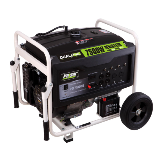
- Page 1 7500 7500B 1-866-591-8921...
-
Page 2: Table Of Contents
7500W Generator Topic Page Safety Guidelines General al Precautions elines General Parts ener l recautions Battery Battery Operation Inspection, Cleaning and Maintenance Installation aintenance Troubleshooting nstallation Specifications Wiring iagram p e ci fications General Parts Listing eneral Parts Listing WARNING! READ AND UNDERSTAND ALL SAFETY PRECAUTIONS IN THIS MANUAL BEFORE OPERATING. -
Page 3: Safety Guidelines
Safety Guidelines - Definitions This manual contains important information that you need to know and understand in order to protect YOUR SAFETY and to PREVENT EQUIPMENT PROBLEMS. The following symbols help you recognize this information. Please read the manual and pay attention to these sections. Save These Important Safety Instructions! Read and understand all of these safety instructions. -
Page 4: General Al Precautions A Gui Elines D
7500W Generator General Precautions WARNING! FAILURE TO FOLLOW THESE INSTRUCTIONS CAN RESULT IN SEVERE INJURY OR DEATH. CAUTION: FAILURE TO FOLLOW THESE INSTRUCTIONS CAN ALSO RESULT IN DAMAGE TO THE TOOL AND/OR THE ITEM YOU ARE WORKING Carbon Monoxide When this tool is running, ensure that the area is well ventilated. Never run the engine in an enclosed area. -
Page 5: Hot Components
CAUTION: ATTEMPTING TO POWER SENSITIVE ELECTRONIC EQUIPMENT WITHOUT THE USE OF AN APPROVED LINE CONDITIONER MAY CAUSE DAMAGE TO THE EQUIPMENT. PULSAR PRODUCTS INC.IS NOT RESPONSIBLE FOR ANY DIRECT OR INDIRECT DAMAGE CAUSED BY FAILURE TO USE AN APPROVED LINE CONDITIONER. -
Page 6: Work Area
7500W Generator General Precautions (cont’d) Work Area • Keep your work area clean and well lit. Cluttered benches and dark areas invite accidents. • Do not operate power tools in explosive atmospheres, such as in the presence of flammable liquids, gases, or dust. Generators create sparks which may ignite the dust or fumes. •... -
Page 7: Personal Safety
Owner’s Manual General Precautions (cont’d) Electrical Safety (cont’d) • All connections and conduits from the generator to the load must only be installed by trained and licensed electricians, and in compliance with all relevant local, state, and federal electrical codes and standards, and other regulations where applicable. •... -
Page 8: Generator Use And Care
7500W Generator General Precautions (cont’d) Personal Safety (cont’d) • Avoid accidental starting. Make sure the power switch is in its “OFF” position and disconnect the spark plug wire when not in use. • Remove adjusting keys or wrenches before turning the generator on. A wrench or a key that is left attached to a rotating part of the generator may result in personal injury. -
Page 9: Heart Pacemakers
Servicing Maintain labels and name plates on the generator and engine. These carry important information. If unreadable or missing, contact Pulsar Products Inc. Immediately for a replacement. Generator service must be performed only by qualified repair personnel. Service or maintenance performed by unqualified personnel could result in a risk of injury. - Page 10 7500W Generator General Precautions (cont’d) Installation (cont’d) • If the generator is installed outdoors, it must be weatherproofed and should be soundproofed. It should not be run outdoors without protection to the generator and wiring conduit. • The generator weighs lbs (approximately) .
- Page 11 Owner’s Manual General Precautions (cont’d) Mechanical (cont’d) • Do not operate the generator with safety guards removed. While the generator is running, do not attempt to reach around the safety guard for maintenance or any other reason. • Keep hands, arms, long hair, loose clothing, and jewelry away from moving parts. Be aware that when engine parts are moving fast they cannot be seen clearly.
-
Page 12: General Parts Ener L Recautions
Owner’s Manual Gen ra l Pa s Frame Fuel tank cap This product does not need a battery. Fuel gauge One way valve Fuel tank Control Panel Choke lever Air filter Wheel Handle Fuel valve Recoil starter Battery Engine key Thermal protector Oil dipstick Drain plug... -
Page 13: Battery
7500 W Ge n erato r Battery AC electrical To start generator with electric start you will need a battery (included) . Also this generator can also be started with the pull start. Note: Using a battery not designed for Current Output 120V/240V 60Hz, 50A/25A this unit may void warranty. -
Page 14: Operation
Owner’s Manual Operation Fuel tank k Lever Choke lever Control panel Fuel valve Pull start NOTE: THE PARTS LISTED ABOVE ARE HELPFUL FOR LOCATING THE CONTROLS MENTIONED BELOW. CAUTION: PRIOR TO FIRST USING THE GENERATOR, THE ENGINE MUST BE FILLED WITH A HIGH QUALITY SAE 10W30 GRADE ENGINE OIL. TO DO SO, UNSCREW AND REMOVE THE ENGINE’S OIL DIPSTICK LOCATED AT THE BOTTOM OF THE ENGINE CRANKCASE. - Page 15 Operation (cont’d) Connecting to LPG Fuel Source When using the fuel as LPG, make sure that there is no gasoline in the engine. 1.Locate the LPG converter on the backside of the generator 2.Attach small end of the Gas Hose to the LPG converter. 3.Connect gas hose to propane fuel source.
-
Page 16: Starting The Generator Set
Operation (cont’d) Starting the Generator Set Ground Terminal Before using generator, a ground wire must be connected to the ground terminal. The Ground terminal is located on the Front Panel. Before using the ground terminal consult a qualified electrician. Ground Terminal Symbol: The 7500Watt dual fuel generator can be started using the following method. - Page 17 Operation (cont’d) 2. Rotate the fuel valve lever to ON position. 3. If the engine is cold: Pull the choke lever out to close the choke. 4. Continue to desired start-up method. RECOIL START METHOD 1. Disconnect all devices from the outlets on the generator panel. 2.
- Page 18 Operation (cont’d) the ignition button for more than 5 seconds. Doing so may damage the alternator. If electric start does not turn on the generator after three attempts, contact customer support. Repeated attempts could damage the ignition mechanism. 3. Follow steps 6-7 from the Recoil Start Method Using the Generator Set 1.
-
Page 19: Stopping The Generator Set
Operation (cont’d) REVERSE POLARITY OF CONNECTIONS) 3. Start the generator. Stopping the Generator Set 1.Turn off all the connected devices. 2.Allow the generator set run for a few minutes to cool down. 3.Stop the generator set by pressing and holding the engine switch in the OFF position until the generator set stops. - Page 20 CAUTION: ATTEMPTING TO POWER SENSITIVE ELECTRONIC EQUIPMENT WITHOUT THE USE OF AN APPROVED LINE CONDITIONER MAY CAUSE DAMAGE TO THE EQUIPMENT. PULSAR PRODUCTS INC. IS NOT RESPONSIBLE FOR ANY DIRECT OR INDIRECT DAMAGE CAUSED BY FAILURE TO USE AN APPROVED LINE CONDITIONER.
- Page 21 7500W Generator Operation (cont’d) Powering 12 Volt DC tools and Equipment: 1. Prior to powering tools and equipment, make sure the generator’s rated voltage, and amperage capacity (12VDC) is adequate to supply all electrical loads that the unit will power. If powering exceeds the generator’s capacity, it may be necessary to group one or more of the tools and/or equipment for connection to a separate generator.
-
Page 22: Spark Plug Service
Owner’s Manual Operation (cont’d) Spark Plug Service In order to service the spark plug, you will need a spark plug wrench (commercially available). Recommended spark plugs: NHSP LD F7TC. To ensure proper engine operation, the spark plug must be properly gapped and free of deposits. 1. -
Page 23: Inspection, Cleaning And Maintenance
Owner’s Manual Inspection, Cleaning, and Maintenance WARNING! ALWAYS MAKE SURE THE ENGINE POWER SWITCH (2) IS IN ITS “OFF” POSITION. DISCONNECT THE SPARK PLUG WIRE FROM THE ENGINE. AND ALLOW SUFFICIENT TIME FOR THE ENGINE AND GENERATOR TO COMPLETELY COOL BEFORE PERFORMING ANY INSPECTIONS, MAINTENANCE, OR CLEANING. -
Page 24: Installation Aintenance
7500W Generator Installation NOTE: PRIOR TO POWERING TOOLS AND EQUIPMENT MAKE SURE THE GENERATOR’S RATED VOLTAGE, WATTAGE AND AMPERAGE CAPACITY IS ADEQUATE TO SUPPLY ALL ELECTRICAL LOADS THAT THE UNIT WILL POWER. IF POWERING EXCEEDS THE GENERATOR’S CAPACITY, IT MAY BE NECCESSARY TO GROUP ONE OR MORE OF THE TOOLS AND/OR EQUIPMENT FOR CONNECTION TO A SEPERATE GENERATOR. - Page 25 Owner’s Manual Installation (cont’d) Supporting and Mounting Mount the generator on a concrete slab capable of supporting the weight of the generator. The slab must extend on all sides beyond the frame by at least one foot. Contact a cement contractor for slab specifications if necessary.
-
Page 26: Troubleshooting
Troubleshooting Note: Troubleshooting problems may have similar causes and solutions. PROBLEM POSSIBLE CAUSE SOLUTION Is there fuel in the tank? Refill the fuel tank. Is there enough oil in the The engine Add the recommended oil. engine? will not start Is the spark plug in good Readjust gap and dry the spark plug. -
Page 27: Specifications
7500 W Ge n erato r Specifications AC electrical Current Output 120V/240V 60Hz, 50A/25A Continuous/rated Wattage 6,000 Peak Wattage 7,500 Outlet 4 AC 120V, 2 AC 120V/240V twist-lock outlet DC electrical none none Gasoline engine Horsepower Type 4-cycle OHV air-cooled recoil start Displacement 389cc Oil capacity... -
Page 28: Wiring
Wiring Diagra Breaker ControlBoxDiagram 3in1 DigitalMeter GNAJ L14-30R L6-30R 5-20R 5-20R Breaker GrQVR1.5mm DCcoil1 LBQVR1.5mm BlQVR1.5mm LBQVR1.5mm 2510 RQVR0.5mm OQVR0.5mm BuQVR0.5mm BrQVR0.5mm DCcoil2 QVR0.5mm BrRQVR0.5mm BrQVR0.5mm QVR0.5mm QVR0.5mm WQVR0.5mm QVR0.5mm QVR0.5mm RQVR0.5mm BuQVR0.5mm BuQVR0.5mm RQVR6mm QVR0.5mm QVR0.5mm QVR0.5mm Oilalertunit QVR0.5mm QVR6mm Engine Fuel... -
Page 29: General Parts Listing Eneral Parts Listing
PG7500B ENGINE PARTS LISTING This This This This list list list list is is is is provided provided provided provided for for reference reference reference reference purposes purposes purposes purposes only.All only.All only.All only.All repairs repairs repairs repairs and and part... - Page 30 PART PART PART PART NO. DESCRIPTION DESCRIPTION DESCRIPTION DESCRIPTION Q'TY Q'TY Q'TY Q'TY REMARK REMARK REMARK REMARK PIN Φ8×14 DJ168F-11002-A CRANKCASE GASKET DJ188F-11003-B SPEED REGULATING GEAR DJ188F-15100-A GB276-89-6207 BEARING RADIAL BALL 6207 DJ188FD-11001-A CRANKCASE COVER ASSEMBLY DJ188FD-11007-D DIPSTICK DJ188F-11014-A OIL SEAL Φ35×Φ52×8 GBT820-B5-12 FLANGE BOLT M5*12 DF6500H-11032-A...
- Page 31 PART DESCRIPTION Q'TY REMARK PART PART PART NO. DESCRIPTION DESCRIPTION DESCRIPTION Q'TY Q'TY Q'TY REMARK REMARK REMARK DJ188FD-14001-A BOLT STUD M8*110 SPARK PLUG F7TC DJ168F-18500-A GBT16674-B10-80 FLANGE BOLT M10*80 DJ188F-11015-A BOLT DJ188F-11300-H CYCLINDER HEAD COVER ASSEMBLY GASKET, CYCLINDER HEAD COVER DJ188F-11011-A DJ188F-11200-LE CYLINDER HEAD ASSEMBLY...
- Page 32 PART PART PART PART NO. DESCRIPTION DESCRIPTION DESCRIPTION DESCRIPTION Q'TY Q'TY Q'TY Q'TY REMARK REMARK REMARK REMARK CRANKSHAFT ASSEMBLY DJ190F-12100-BE GB276-89-6202 BALL RADIAL BEARING 6202 DJ188F-12004-A BALANCING SHAFT DJ190F-12300-C PISTON RING SET DJ188F-12003-A PISTON PIN CIR-CLIP DJ190F-12001-D PISTON DJ188F-12002-A PISTON PIN DJ190F-12200-AE CONNECTING ROD ASSEMBLY...
- Page 33 PART DESCRIPTION Q'TY REMARK PART PART PART NO. DESCRIPTION DESCRIPTION DESCRIPTION Q'TY Q'TY Q'TY REMARK REMARK REMARK ROCKER ARM ASSEMBLY DJ188F-13200-A DJ188F-13300-A PUSH ROD GUIDE DJ188F-13006-A DJ188F-13005-A VALVE RETURNER EXHAUST VALVE RETURNER INTAKE DJ188F-13004-A DJ188F-13003-A VALVE SPRING DJ188F-13002-B EXHAUST VALVE DJ188F-13001-A INTAKE VALVE DJ188F-13011-A...
- Page 34 PART PART PART PART NO. DESCRIPTION DESCRIPTION DESCRIPTION DESCRIPTION Q'TY Q'TY Q'TY Q'TY REMARK REMARK REMARK REMARK DJ188F-14027-A SPACER,CARBURETOR DJ190FD-14100-D CARBURETOR ASSEMBLY ASKET - 1 4004 14005 DJ188F-14005-B GASKET, CARBURETOR 14003 INLET - 11039 CONNECTING BLOCK, CARBURETOR DJ188F-14004-A 14008 DJ188F-14003-B GASKET,INTET LINE CLIP...
- Page 35 PART PART PART PART NO. DESCRIPTION DESCRIPTION DESCRIPTION DESCRIPTION Q'TY Q'TY Q'TY Q'TY REMARK REMARK REMARK REMARK DJ188FD-14200-C AIR FILTER ASSEMBLY DJ188FD-14204-A AIR FILTER CAP DJ188FD-14201-A FILTER ELEMENT DJ188FD-14203-C BOTTOM CAP,AIR FILTER GB6177-N-6 NUT M6 DJ188FD-11013-A TUBE BREATHER DF6500H-14205-A BRACKET,AIR FILTER...
- Page 36 PART PART DESCRIPTION DESCRIPTION Q'TY Q'TY REMARK REMARK PART PART NO. DESCRIPTION DESCRIPTION Q'TY Q'TY REMARK REMARK FLANGE BOLT M6*12 GBT16674-B6-12 DJ188F-16100-F-116 CASE COMP RECOIL STARTER STARTER DJ168F-16110-A DJ188F-16111-A ROPE DJ188F-16130-F-116 STARTER COMP,RECOIL 92140-B6-8 FLANGE BOLT M6*8 GBT97-W-6 PLAIN WASHER DJ188F-16101-A-116 RECOIL STARTER CASE...
- Page 37 PART PART PART PART NO. DESCRIPTION DESCRIPTION DESCRIPTION DESCRIPTION Q'TY Q'TY Q'TY Q'TY REMARK REMARK REMARK REMARK FLANGE BOLT M6*12 GBT16674-B6-12 DJ188FD-15200-A SPEED REGULATOR DJ188F-15008-A FINE REGULATING SPRING C PULLING ROD DJ188F-15006-A BACK SPRING B DJ188F-15007-A DJ188F-15004-A SPEED REGULATING ARM DJ168F-15005-A LOCK BOLT GB6177-N-6...
- Page 38 PART PART PART PART NO. DESCRIPTION DESCRIPTION DESCRIPTION DESCRIPTION Q'TY Q'TY Q'TY Q'TY REMARK REMARK REMARK REMARK DJ188F-16205-A NUT M16*1.5 DJ188F-16000-A STARTING CUP IMPELLER DJ188F-16002-A DJ188F-16200-BE FLYWHEEL ASSEMBLY GBT16674-B6-25 FLANGE BOLT M6*25 IGNITION COIL ASSEMBLY DJ188F-18100-C GBT16674-B6-8 FLANGE BOLT M6*8 CLAMPER CORD A DJ168F-18007-A GBT16674-B8-35...
- Page 39 PG7500B GENERAL PARTS LISTING This This This This list list list list is is is is provided provided provided provided for for reference reference reference reference purposes purposes purposes purposes only.All only.All only.All only.All repairs repairs repairs repairs and and part...
- Page 40 PART PART PART PART NO. DESCRIPTION DESCRIPTION DESCRIPTION DESCRIPTION Q'TY Q'TY Q'TY Q'TY REMARK REMARK REMARK REMARK GBT16674-B6-16 FLANGE BOLT M6*16 DF2500H-34106-A GASKET DFD6500H-34100-QQ01 CONTROL PANEL ASSEMBLY 34203-010 SWITCH ASSEMBLY 34290-002 VOLTAGE.FREQUENCY.HOUR METER 34204-038 GROUNDING POST 34204-039 GROUNDING POST 34204-062 120V DUPLEX OUTLET 34204-003 120V/240V TWIST-LOCK OUTLET...
- Page 41 PART PART PART PART NO. DESCRIPTION DESCRIPTION DESCRIPTION DESCRIPTION Q'TY Q'TY Q'TY Q'TY REMARK REMARK REMARK REMARK DJ188FD-14010-C GASKET,EXHAUST PIPE SPRING WASHER GBT93-LW-8 GB6170-N-8 FLANGE NUT M8 DJ188FD-14009-A MUFFLER CONNECTING PIPE GBT16674-B8-30 FLANGE BOLT M8*30 MUFFER ASSEMBLY DF5500H-14400-DB GBT16674-B6-12 FLANGE BOLT M6*12 DF3800H-14018-A OUTER HOOD DF3800H-14403-A...
- Page 42 PART PART DESCRIPTION DESCRIPTION Q'TY Q'TY REMARK REMARK PART PART NO. DESCRIPTION DESCRIPTION Q'TY Q'TY REMARK REMARK DF6500H-33100-BJ-23702D ALTERNATOR ASSEMBLY DF6500H-33120-BJ ROTOR CARBON BRUSH COMP. DF3800H-33001-A DF3800H-33002-B GROUNDING POST COMP. DF6500H-33110-BJ-23702D STATOR DF3800H-33005-A ALTERNATOR END BRACKET GB6170-N-5-H NUT M5 PLAIN WASHER GBT97-W-5 GBT93-LW-5 SPRING WASHER...
- Page 43 PART DESCRIPTION Q'TY REMARK PART PART PART NO. DESCRIPTION DESCRIPTION DESCRIPTION Q'TY Q'TY Q'TY REMARK REMARK REMARK 31100 DF6500H-31058-A-117 HANDLE ASSEMBLY GBT16674-B8-45 FLANGE BOLT M8*45 DF6500H-31073-A HANDLE PLUG Φ25 DF6500H-31074-A FIXING BUSH,HANDLE GB6177-N-8 FLANGE NUT M8 DF6500H-31016-A RUBBER,HANDLE RPG6250-31100-B-117 FRAME ASSEMBLY GB6170-N-6 FLANGE NUT M6 DF6500H-31020-A-117...
Need help?
Do you have a question about the PG7500B and is the answer not in the manual?
Questions and answers