Table of Contents
Advertisement
Quick Links
USB Programmable, DIN Form B
Connection Head Transmitter
Model ST132-0600 & ST132-0610
Two-Wire Transmitter, TC Input
USER'S MANUAL
ACROMAG INCORPORATED
Tel: (248) 295-0880
30765 South Wixom Road
email: sales@acromag.com
Wixom, MI 48393-2417 U.S.A.
Copyright 2011, Acromag, Inc., Printed in the USA.
8500896L
Data and specifications are subject to change without notice.
Advertisement
Table of Contents

Related Manuals for Acromag ST132-0600


Summary of Contents for Acromag ST132-0600
- Page 1 Model ST132-0600 & ST132-0610 Two-Wire Transmitter, TC Input USER’S MANUAL ACROMAG INCORPORATED Tel: (248) 295-0880 30765 South Wixom Road email: sales@acromag.com Wixom, MI 48393-2417 U.S.A. Copyright 2011, Acromag, Inc., Printed in the USA. 8500896L Data and specifications are subject to change without notice.
-
Page 2: Table Of Contents
This is very important where property Symbols on equipment: loss or human life is involved. It is important that you perform satisfactory overall system design and it is agreed between you and Acromag, that this is your responsibility. GETTING STARTED Means “Refer to User’s DESCRIPTION….…………………….………..……….. -
Page 3: Description
MiniPuck Model ST132-06x0 Two-Wire TC/mV Transmitter ________________________________________________________________________________ The ST132-0600 is an ANSI/ISA Type II transmitter designed to interface DESCRIPTION with a TC (Thermocouple) sensor, or ±100mV input, and modulate a 4- 20mA current signal for a two-wire current loop. This unit is setup and calibrated using the included software and a USB connection to Windows- based PC’s. -
Page 4: Mechanical Dimensions
G-Type DIN Rail The M4 mounting screws and relief springs used to attach the transmitter to the connection head are ordered separately via Acromag Mounting Kit ST130-MTG (see Accessories section). The unit may be optionally mounted to 35mm T-type or G-type DIN rail using the optional DIN mounting kit ST130-DIN as shown at left (see Accessories section). -
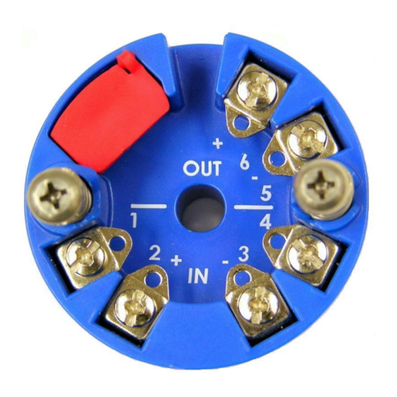
Page 5: Electrical Connections
Connect a DC power supply and load in series in the two-wire loop as shown in the drawing below. ______________________________________________________________________________________ Acromag, Inc. Tel:248-295-0880 Fax:248-624-9234 Email:sales@acromag.com http://www.acromag.com... - Page 6 “sourcing” inputs. Other receivers that do not provide excitation are referred to as “sinking” inputs, and these will require that a separate power supply connect in the loop. ______________________________________________________________________________________ Acromag, Inc. Tel: 248-295-0880 Email: sales@acromag.com...
-
Page 7: Earth Ground Connections
USB connection to the transmitter, which should be made via a USB isolator, as most Personal Computers earth ground their USB ports, and this makes contact with both the signal and shield grounds. ______________________________________________________________________________________ Acromag, Inc. Tel:248-295-0880 Fax:248-624-9234 Email:sales@acromag.com http://www.acromag.com... -
Page 8: Usb Connections
USB energy levels could ignite explosive gases or particles in the air. • USB Signal Isolation Required (See Below) - You may use Acromag model USB-ISOLATOR to isolate your USB port, or you can optionally use another USB signal isolator that supports USB Full Speed operation ELECTRICAL (12Mbps). -
Page 9: Configuration Software
You can optionally set this up for a reverse- control to get a Help message acting output by swapping the signals. pertaining to the item you pointed to. ______________________________________________________________________________________ Acromag, Inc. Tel:248-295-0880 Fax:248-624-9234 Email:sales@acromag.com http://www.acromag.com... - Page 10 You can click the “Restore Factory Settings” button if you ever mis calibrate or misconfigure a transmitter in such a way that its operation appears erratic. ______________________________________________________________________________________ Acromag, Inc. Tel: 248-295-0880 Email: sales@acromag.com https://www.acromag.com...
-
Page 11: Troubleshooting
USB power. required. Repair services are Cannot Communicate with Transmitter via USB… also available from Acromag. A missing USB Isolator could A ground loop is created between a cause a ground loop when normally grounded two-wire current loop connecting to USB from a and earth ground of the PC USB port. - Page 12 Acromag has automated test equipment that thoroughly checks and calibrates the performance of each transmitter and restores firmware. Please refer to Acromag’s Service Policy and Warranty Bulletins or contact Acromag for complete details on how to obtain repair or replacement. ______________________________________________________________________________________ Acromag, Inc.
-
Page 13: Technical Reference
I/O circuits and the microcontroller. The 4 to 20mA output is generated from the microcontroller’s built in 16-bit DAC using a voltage to current circuit. ______________________________________________________________________________________ Acromag, Inc. Tel:248-295-0880 Fax:248-624-9234 Email:sales@acromag.com http://www.acromag.com... -
Page 14: Configuration Step-By-Step
Apply power to the transmitter output loop and always power the loop before connecting to USB. You will not be able to calibrate the unit without loop power applied. ______________________________________________________________________________________ Acromag, Inc. Tel: 248-295-0880 Email: sales@acromag.com https://www.acromag.com... - Page 15 Note (Table): Shaded cells refer to the calibration range end points used to calibrate the T/C type for this model. Bold column entries refer to the nominal T/C input range end points of this model. ______________________________________________________________________________________ Acromag, Inc. Tel:248-295-0880 Fax:248-624-9234 Email:sales@acromag.com http://www.acromag.com...
-
Page 16: Reconfiguration
MiniPuck Model ST132-06x0 Two-Wire TC/mV Transmitter _________________________________________________________________________________ CONFIGURATION STEP-BY-STEP Reconfiguration After executing the Acromag Configuration software for this model, a screen similar to the one at right will appear, if you have not already connected to your transmitter via USB (note some fields are faded out under these conditions). - Page 17 HELP – You can press F1 for lower left corner of the screen. Additionally, the device Product Name field displays the Model, the Manufacturer field displays “Acromag, Inc.”, and the Help on a selected or Serial field displays this model’s serial number. Additionally, most of the highlighted field or control.
- Page 18 You can select the amount of filtering as None, Low, Medium, or High. Note the approximate response times indicated next to each filter level. ______________________________________________________________________________________ Acromag, Inc. Tel: 248-295-0880 Email: sales@acromag.com https://www.acromag.com...
- Page 19 Note that some under-range and over-range is built-into the unit, as the output can swing as low as 3.5mA, and as high as 24mA. Actual endpoint limits will vary slightly between units. ______________________________________________________________________________________ Acromag, Inc. Tel:248-295-0880 Fax:248-624-9234 Email:sales@acromag.com http://www.acromag.com...
-
Page 20: Zero & Full-Scale Calibration
Since not all input levels can be validated during field programming, connecting or entering incorrect signals will produce an undesired output response. ______________________________________________________________________________________ Acromag, Inc. Tel: 248-295-0880 Email: sales@acromag.com https://www.acromag.com... - Page 21 1. First, calibrate the TC Type J input range as shown above. 2. Connect a TC Type J ice point reference to the device input terminals. 3. Click on the “Tref-Cal” button. 4. In the pop-up box, click “OK”. ______________________________________________________________________________________ Acromag, Inc. Tel:248-295-0880 Fax:248-624-9234 Email:sales@acromag.com http://www.acromag.com...
-
Page 22: Other Configuration Controls
This button will restore ALL configuration settings and calibration to their original factory settings. ______________________________________________________________________________________ Acromag, Inc. Tel: 248-295-0880 Email: sales@acromag.com... - Page 23 “Restoring factory calibration.” “Error occurred during calibration restore, try again.” “Restore successful” “Restore cancelled” “Restoring to “Out-of-Box” condition.” “Error occurred during restore, try again.” “”Out-of-Box” restore successful.” “”Out-of-Box” restore cancelled.” “Resetting ST13x.” “Reset complete.” ______________________________________________________________________________________ Acromag, Inc. Tel:248-295-0880 Fax:248-624-9234 Email:sales@acromag.com http://www.acromag.com...
-
Page 24: Specifications
_________________________________________________________________________________ Model Number: SPECIFICATIONS ST13/Input-Isolation/Power/Approvals/SIL-Calibration Model Numbers Model ST132-0600 ST13 is the model Series. The prefix “ST” denotes the “Smart Transmitter” Signal Transmitter family. The trailing “2” digit denotes an TC input type. The “0” after the TC Input hyphen denotes non-isolated, the “6” that follows denotes 2-wire loop Non-Isolated powered. - Page 25 This includes the effects of repeatability, terminal point conformity, and linearization, but does not include sensor error. Measurement Temperature Drift: Better than 75ppm/C (±0.0075%/C). Analog to Digital Converter (A/D): A 24-bit - converter. ______________________________________________________________________________________ Acromag, Inc. Tel:248-295-0880 Fax:248-624-9234 Email:sales@acromag.com http://www.acromag.com...
-
Page 26: Output
Output Ripple: Less than ±0.01% of output span. Output Limiting: Output current is limited to less than 25mA, typical. Output Compliance: 17V Minimum, 18V Typical, with a 24V supply and 20mA loop current. ______________________________________________________________________________________ Acromag, Inc. Tel: 248-295-0880 Email: sales@acromag.com https://www.acromag.com... -
Page 27: Usb Interface
Inrush Current Limiting: Unit includes series inrush current limiting at its USB power connection. Cable Length/Connection Distance: 5.0 meters maximum. Driver: Not required. Transmitter uses the built-in Human Interface Device (HID) USB drivers of the Windows Operating System. ______________________________________________________________________________________ Acromag, Inc. Tel:248-295-0880 Fax:248-624-9234 Email:sales@acromag.com http://www.acromag.com... -
Page 28: Enclosure And Physical
Operating Temperature: -40C to +80C (-40F to +176F). Storage Temperature: -40C to +85C (-40F to +185F). ______________________________________________________________________________________ Acromag, Inc. Tel: 248-295-0880 Email: sales@acromag.com https://www.acromag.com... -
Page 29: Reliability Prediction
Configuration Controls (Software Configuration Only via USB) This transmitter produces an analog output current proportional to a sensor input based on the voltage measured across the sensor. No switches or potentiometers are used to make adjustments to this ______________________________________________________________________________________ Acromag, Inc. Tel:248-295-0880 Fax:248-624-9234 Email:sales@acromag.com http://www.acromag.com... -
Page 30: Accessories
ST130 enclosure. Order 1 kit per transmitter. USB Isolator – Order USB-ISOLATOR • USB Signal Isolator • USB A-B Cable 4001-112 • Instructions 8500-900 ______________________________________________________________________________________ Acromag, Inc. Tel: 248-295-0880 Email: sales@acromag.com https://www.acromag.com... -
Page 31: Usb Isolator
ST130 Smart Transmitter to allow it to be snapped onto 35mm T-type DIN rail, or G-type DIN Rail. The screws and springs of this kit are identical to those provided in the Transmitter Mounting Kit ST13C- MTG. NOTES: ______________________________________________________________________________________ Acromag, Inc. Tel:248-295-0880 Fax:248-624-9234 Email:sales@acromag.com http://www.acromag.com... - Page 32 (11/20/13: 8500895J was incorrectly revised to K on ECN 13L001.) 08 APR 2019 FJM/ARP Added Long-Term Stability/Recalibration section. 08 AUG 2019 FJM/ARP Change the default state configuration to -40°F to 176°F (-40°C to 80°C) on page 24. ______________________________________________________________________________________ Acromag, Inc. Tel: 248-295-0880 Email: sales@acromag.com https://www.acromag.com...
Need help?
Do you have a question about the ST132-0600 and is the answer not in the manual?
Questions and answers