Table of Contents
Advertisement
Product Manual
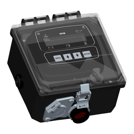
Engine Display & Control Panel
Mechanical Engine
Part Number: C3M-G7230-AS
Revision: 1.1
______________________________________________________________________________________________________________________________________
Copyright Controls, Inc.
P.O. Box 368 • Sharon Center, OH 44274
Phone 330.239.4345 • Fax 330.239.2845 • www.controlsinc.com
Advertisement
Table of Contents

Related Manuals for Controls C3M-G7230-AS


Summary of Contents for Controls C3M-G7230-AS
- Page 1 Product Manual Engine Display & Control Panel Mechanical Engine Part Number: C3M-G7230-AS Revision: 1.1 ______________________________________________________________________________________________________________________________________ Copyright Controls, Inc. P.O. Box 368 • Sharon Center, OH 44274 Phone 330.239.4345 • Fax 330.239.2845 • www.controlsinc.com...
-
Page 2: Table Of Contents
CONTROLS, INCORPORATED C O N T R O L S Y S T E M S & S O L U T I O N S TABLE OF CONTENTS PANEL OPERATION …………….…………………………………………………………………………………….…………………………….………. MANUAL OPERATION AUTO START/STOP OPERATION SLEEP MODE MODULE CONNECTORS …………………………………………………………………………………………………….………………….………. -
Page 3: Panel Operation
CONTROLS, INCORPORATED C O N T R O L S Y S T E M S & S O L U T I O N S PANEL OPERATION MANUAL OPERATION 1) Engine Start - Turn key to CRANK position 2) Engine Stop - Turn key to OFF position... -
Page 4: Module Connectors
CONTROLS, INCORPORATED C O N T R O L S Y S T E M S & S O L U T I O N S MODULE CONNECTORS Primary Connector Secondary Connector 14 Pin 23 Pin - 3 -... -
Page 5: Primary 14 Pin Module Connector
CONTROLS, INCORPORATED C O N T R O L S Y S T E M S & S O L U T I O N S PRIMARY CONNECTOR (14 Pin) Function Function Fuel Solenoid Switched Battery to Horn Battery Positive... -
Page 6: 16 Pin Engine Harness Connector
CONTROLS, INCORPORATED C O N T R O L S Y S T E M S & S O L U T I O N S PANEL CONNECTORS Engine Harness Connector –Deutsch 16 pin (HDP24-24-21PE) 16 Pin Engine Harness Connector... -
Page 7: Float Connector
CONTROLS, INCORPORATED C O N T R O L S Y S T E M S & S O L U T I O N S FLOAT CONNECTOR The controller has a four pin, single / dual float connector integrated to the bottom of the control panel. -
Page 8: Engine Alarms, Codes And Messages
CONTROLS, INCORPORATED C O N T R O L S Y S T E M S & S O L U T I O N S ENGINE ALARMS, CODES AND MESSAGES WARNINGS & ALARMS When parameter is outside of its limits, the control panel flashes that parameter the display and illuminates the yellow lamp. -
Page 9: Indication Lamps
CONTROLS, INCORPORATED C O N T R O L S Y S T E M S & S O L U T I O N S INDICATION LAMPS The panel has two lamp indicators. Engine Engine Warning Fault/Shutdown Lamp Lamp... -
Page 10: Control Panel Specific Alarms And Shut Downs
CONTROLS, INCORPORATED C O N T R O L S Y S T E M S & S O L U T I O N S CONTROL PANEL SPECIFIC ALARMS AND SHUT DOWNS The panel has its own engine safety alarms and shut downs that can be enabled. These alarms and shut downs are managed by the control panel independent from the engine ECU. -
Page 11: Control Panel Relay Outputs
CONTROLS, INCORPORATED C O N T R O L S Y S T E M S & S O L U T I O N S CONTROL PANEL RELAY OUTPUTS The panel provides relay outputs defined below located in the Output Configuration menu. The relays are rated at 5 amps. - Page 12 CONTROLS, INCORPORATED C O N T R O L S Y S T E M S & S O L U T I O N S f. Engine Run - Relay will be active when engine RPM is greater than 600. Typically used to drive an auxiliary circuit such as louvers or send a signal to a monitoring station.
-
Page 13: Service/Maintenance Messages
CONTROLS, INCORPORATED C O N T R O L S Y S T E M S & S O L U T I O N S SERVICE/MAINTENANCE MESSAGES Maintenance intervals and messages can be enabled. Maintenance Configuration Menu Service Interval Message On/Off... -
Page 14: Battery Recharge Monitor
CONTROLS, INCORPORATED C O N T R O L S Y S T E M S & S O L U T I O N S BATTERY RECHARGE MONITOR A battery recharge monitoring system is available to start and run the engine to keep the battery system charged. -
Page 15: Menu System
CONTROLS, INCORPORATED C O N T R O L S Y S T E M S & S O L U T I O N S MENU SYSTEM To Enter Menu System Hold MENU button and press ENTER button. Menu Navigation Press MENU button to scroll menu options. -
Page 16: Viewing Menus
CONTROLS, INCORPORATED C O N T R O L S Y S T E M S & S O L U T I O N S MAIN MENUS Operation Event Log View Last 32 Events (Start, Stop, Alarms) Alarms Event Log... -
Page 17: Configuration Menus
CONTROLS, INCORPORATED C O N T R O L S Y S T E M S & S O L U T I O N S CONFIGURATION MENUS Input Configuration Digital Input 1 - Pre Set to Auto Start Digital Input 2 Setup (NO/NC, Action, Message, When Active, Delay) - Page 18 CONTROLS, INCORPORATED C O N T R O L S Y S T E M S & S O L U T I O N S Engine Safety Configuration Sender Check Bypass Time Period Selection Fuel Level Check On/Off Selection...
- Page 19 CONTROLS, INCORPORATED C O N T R O L S Y S T E M S & S O L U T I O N S Auto Start Configuration Auto Start Delay (Default = 10 seconds) Pre Heat Time (Default = 0 seconds)
- Page 20 #2 Release Trip #2 Release Speed #2 Release Load #2 Release Delay #2 Release Interval Speed Calibration (13) Flywheel Teeth (Default = 30) Auto Set Teeth? (Default = No) Telemetry Parameters (14) Contact Controls, Inc. for details - 19 -...
Need help?
Do you have a question about the C3M-G7230-AS and is the answer not in the manual?
Questions and answers