
Related Manuals for Controls MVP-702


Summary of Contents for Controls MVP-702
- Page 1 Product Manual Pump Display & Control Panel J1939 and Mechanical Engines Part Number: MVP-702 Revision: 3.0 Copyright @ Controls, Inc P.O. Box 368 • Sharon Center, OH 44274 Phone 330.239.4345 • Fax 330.239.2845 • www.controlsinc.com...
- Page 2 CONTROLS, INCORPORATED C O N T R O L S Y S T E M S & S O L U T I O N S TABLE OF CONTENTS INSTALLATION INFORMATION ……...………………………………...……………………………………………………………..MODULE CONNECTOR ……......………………………………...…………………………………………………………………. ENGINE ALARMS, CODES AND MESSAGES ………………………………………………………………………….…...……..
- Page 3 CONTROLS, INCORPORATED C O N T R O L S Y S T E M S & S O L U T I O N S INSTALLATION INFORMATION...
- Page 4 CONTROLS, INCORPORATED C O N T R O L S Y S T E M S & S O L U T I O N S MODULE CONNECTOR INFORMATION BATTERY + DIGITAL INPUT #1 CAN HIGH FUEL/RUN CAN LOW TEMP INPUT...
- Page 5 CONTROLS, INCORPORATED C O N T R O L S Y S T E M S & S O L U T I O N S CONTROL PANEL SPECIFIC ALARMS AND SHUT DOWNS The panel has its own engine safety alarms and shut downs that can be enabled. These alarms and shut downs are managed by the control panel.
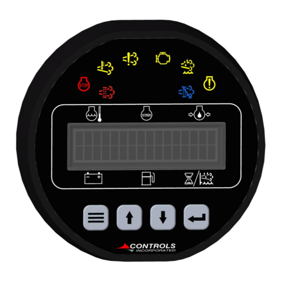
- Page 6 CONTROLS, INCORPORATED C O N T R O L S Y S T E M S & S O L U T I O N S Indicator Lamps Engine Emissions Fault Lamp Regen Lamp Active Lamp Lamp Engine Engine Pre Alarm...
- Page 7 CONTROLS, INCORPORATED C O N T R O L S Y S T E M S & S O L U T I O N S CONTROL PANEL ANALOG AND DIGITAL INPUTS The panel has one analog input and up to one digital input (close to ground) available to monitor other components, senders or signals.
- Page 8 CONTROLS, INCORPORATED C O N T R O L S Y S T E M S & S O L U T I O N S Digital Function Activation 1) Off / Always / Run – Describes when the parameter will be monitored for alarm conditions.
- Page 9 CONTROLS, INCORPORATED C O N T R O L S Y S T E M S & S O L U T I O N S MENU SYSTEM To Enter Menu System Hold MENU button and press ENTER button. Menu Navigation Press MENU button to scroll menu options.
- Page 10 CONTROLS, INCORPORATED C O N T R O L S Y S T E M S & S O L U T I O N S Main Menus Main Menus Sub Menus Active Engine Fault Codes View/Scroll Active Fault Codes...
- Page 11 CONTROLS, INCORPORATED C O N T R O L S Y S T E M S & S O L U T I O N S Configuration Menus Quick Setup Engine Type – Default = Mechanical Flywheel Teeth Preheat Time...
- Page 12 CONTROLS, INCORPORATED C O N T R O L S Y S T E M S & S O L U T I O N S Module Configuration Preheat Time Low Power Mode Power Save Delay Pre-Alarms Displayed (Default = 4)
- Page 13 CONTROLS, INCORPORATED C O N T R O L S Y S T E M S & S O L U T I O N S (11) Emissions Configuration DEF Level Check (Default = Off) Low DEF Pre Alarm (Default = 16%) Low DEF Alarm (Default = 0%) DEF Alarm Delay (Default = 5 Sec.)
Need help?
Do you have a question about the MVP-702 and is the answer not in the manual?
Questions and answers