Table of Contents
Advertisement
Product Manual
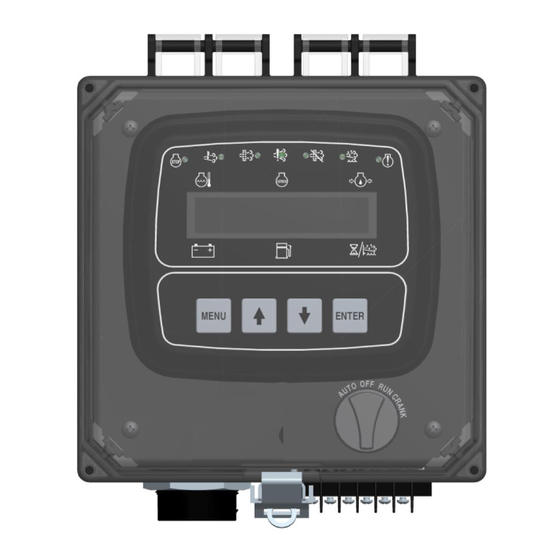
Engine Display & Control Panel
J1939 Engines
Part Number: C4F-F10198 (12v System)
Revision: 1.0
______________________________________________________________________________________________________________________________________
Copyright Controls, Inc.
P.O. Box 368 • Sharon Center, OH 44274
Phone 330.239.4345 • Fax 330.239.2845 • www.controlsinc.com
Advertisement
Table of Contents

Related Manuals for Controls C4F-F10198


Summary of Contents for Controls C4F-F10198
- Page 1 Product Manual Engine Display & Control Panel J1939 Engines Part Number: C4F-F10198 (12v System) Revision: 1.0 ______________________________________________________________________________________________________________________________________ Copyright Controls, Inc. P.O. Box 368 • Sharon Center, OH 44274 Phone 330.239.4345 • Fax 330.239.2845 • www.controlsinc.com...
-
Page 2: Table Of Contents
CONTROLS, INCORPORATED C O N T R O L S Y S T E M S & S O L U T I O N S TABLE OF CONTENTS PRIOR TO STARTING ENGINE……... ……………………………………………………………………..……………….…………... THROTTLE SETTINGS PANEL OPERATION……..……..… ……………………………………….………………………………………….………………..ENGINE START, STOP AND THROTTLE MODULE CONNECTOR …...………………………………………………………..…………………………………….………………………... -
Page 3: Prior To Starting Engine
CONTROLS, INCORPORATED C O N T R O L S Y S T E M S & S O L U T I O N S PRIOR TO STARTING ENGINE Prior to starting the engine, select the proper throttle control mode required for application. -
Page 4: Panel Operation
CONTROLS, INCORPORATED C O N T R O L S Y S T E M S & S O L U T I O N S PANEL OPERATION 1) Engine Start - Turn key to run position 2) Engine Stop - Turn key to off position... -
Page 5: Module Connector
CONTROLS, INCORPORATED C O N T R O L S Y S T E M S & S O L U T I O N S MODULE CONNECTORS Primary Connector 14 Pin - 4 -... - Page 6 CONTROLS, INCORPORATED C O N T R O L S Y S T E M S & S O L U T I O N S Primary Connector (14 Pin) Function Function Relay #2 -ECU Signal J1939 Low Relay #1...
-
Page 7: Panel Connector
CONTROLS, INCORPORATED C O N T R O L S Y S T E M S & S O L U T I O N S PANEL CONNECTORS Engine Harness Connector –Deutsch 21 pin (HDP24-24-21PE) Engine Harness Connector (21 Pin) -
Page 8: Engine Alarms, Codes And Messages
CONTROLS, INCORPORATED C O N T R O L S Y S T E M S & S O L U T I O N S ENGINE ALARMS, CODES AND MESSAGES Engine ECU Alarm/De-Rate/Shut Downs It is important to understand panel operation with respect to engine safety protections, alarms, and fault codes. -
Page 9: Active And Stored Engine Ecu Codes
CONTROLS, INCORPORATED C O N T R O L S Y S T E M S & S O L U T I O N S Indicator Lamps The panel has six lamp indicators. Regen Regen Active Inhibit Alert Lamp... -
Page 10: Control Panel Specific Alarms And Shut Downs
CONTROLS, INCORPORATED C O N T R O L S Y S T E M S & S O L U T I O N S CONTROL PANEL SPECIFIC ALARMS AND SHUT DOWNS The panel has its own engine safety alarms and shut downs that can be enabled. These alarms and shut downs are managed by the control panel independent from the engine ECU. -
Page 11: Control Panel Analog And Digital Inputs
CONTROLS, INCORPORATED C O N T R O L S Y S T E M S & S O L U T I O N S CONTROL PANEL ANALOG AND DIGITAL INPUTS The panel is shipped from the factory with the bold print inputs pre-wired and enabled in the panel. - Page 12 CONTROLS, INCORPORATED C O N T R O L S Y S T E M S & S O L U T I O N S Normally Open Function Available Digital 8 Message None Check Normally Open Function Available Digital 9...
- Page 13 CONTROLS, INCORPORATED C O N T R O L S Y S T E M S & S O L U T I O N S DIGITAL FUNCTIONS The digital inputs can be configured for different uses depending on the application. These include the following: 1) Alarm –...
-
Page 14: Control Panel Relay Outputs
CONTROLS, INCORPORATED C O N T R O L S Y S T E M S & S O L U T I O N S CONTROL PANEL RELAY OUTPUTS The panel provides relay outputs defined below located in the Output Configuration menu. The relays are rated at 5 amps. - Page 15 CONTROLS, INCORPORATED C O N T R O L S Y S T E M S & S O L U T I O N S f. Engine Run - Relay will be active when engine RPM is greater than 600. Typically used to drive an auxiliary circuit such as louvers or send a signal to a monitoring station.
-
Page 16: Menu System
CONTROLS, INCORPORATED C O N T R O L S Y S T E M S & S O L U T I O N S MENU SYSTEM To Enter Menu System Hold MENU button and press ENTER button. Menu Navigation Press MENU button to scroll menu options. - Page 17 CONTROLS, INCORPORATED C O N T R O L S Y S T E M S & S O L U T I O N S Main Menus Emissions Parameters Regen Options (Auto, Inhibit, Request) DEF Level DPF Soot Load % View...
- Page 18 CONTROLS, INCORPORATED C O N T R O L S Y S T E M S & S O L U T I O N S Configuration Menus Input Configuration Digital Input 1 Setup (NO/NC, Action, Message, When Active, Delay)
- Page 19 CONTROLS, INCORPORATED C O N T R O L S Y S T E M S & S O L U T I O N S Engine Safety Configuration Sender Check Bypass Time Period Selection Fuel Level Check On/Off Selection...
- Page 20 CONTROLS, INCORPORATED C O N T R O L S Y S T E M S & S O L U T I O N S Emissions Configuration TSC Regen Speed Selection Allow Service Regen Yes/No (Deere Only) Regen Interlock On/Off...
Need help?
Do you have a question about the C4F-F10198 and is the answer not in the manual?
Questions and answers