Table of Contents
Advertisement
Quick Links
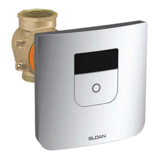
TRUFLUSH ELECTRONIC CLOSET AND URINAL FLUSHOMETERS
PRIOR TO INSTALLATION
his valve is designed for new construction or where there is easily
T
accessed plumbing for the fixture and the valve.
This valve is designed for minimum six inch (152 mm) wall space
depth. Distance from center of the valve (inlet or outlet pipe) to the
finished surface of the wall can vary from 2"-3" (51-76 mm).
TOOLS REQUIRED FOR INSTALLATION
• Smooth-jawed wrench (at least 2") • Phillips screwdriver • 5/64" hex wrench (supplied) • Adjusting tool (supplied) • Flathead screwdriver .118"
(3 mm or below) • Wire stripper tool
ITEMS INCLUDED WITH THE PRODUCT
VALVE BOX
1. Wall Box and Electronic Valve Assembly
2. Mud Guard
3. Adjustment Tool
4. (2) #8-32 x 2" screws to secure mud guard
5. (2) 1/4"-20 x 2" screws to remove activation
assembly
6. Installation instructions
WALL PLATE BOX
1. Wall Bracket
2. Wall Plate
3. Sensor Assembly
4. Activation Button
5. Battery Pack
6. (4) Batteries
7.(4) #8-32 x 2 Screws
8. Allen Key
9. Installation instructions
INSTALLATION INSTRUCTIONS FOR
TruFlush Models:
TRF 8156-1.6
TRF 8156-1.28
TRF 8156-1.1
TRF 8196-0.5
TRF 8196-0.25
TRF 8196-0.125
1. Wall box and electronic
Valve Asembly
1. Wall Bracket
5. Battery Pack
LIMITED WARRANTY
Unless otherwise noted, Sloan Valve Company warrants this product,
manufactured and sold for commercial or industrial uses, to be free
from defects in material and workmanship for a period of three (3)
years (one (1) year for special finishes, SF faucets, PWT electronics
and 30 days for PWT software) from date of first purchase. During
this period, Sloan Valve Company will, at its option, repair, replace, or
refund the purchase price of any product which fails to conform with
this warranty under normal use and service. This shall be the sole and
exclusive remedy under this warranty. Products must be returned to
Sloan Valve Company, at customer's cost. No claims will be allowed
for labor, transportation or other costs. This warranty extends only
to persons or organizations who purchase Sloan Valve Company's
products directly from Sloan Valve Company for purpose of resale.
This warranty does not cover the life of the batteries.
THERE ARE NO WARRANTIES WHICH EXTEND
BEYOND THE DESCRIPTION ON THE FACE
HEREOF. IN NO EVENT IS SLOAN VALVE COMPANY
RESPONSIBLE FOR ANY CONSEQUENTIAL
DAMAGES OF ANY MEASURE WHATSOEVER.
Wall plate opening must be of 5.6" x 5.6" (142 x 142 mm). Mud plate
is provided and must accompany valve for proper installation. Mud
plate is removed after wall is finished.
3. Adjustment Tool
2. Mud Guard
5. Activation Assembly
Screws
2. Wall Plate
3.Sensor Assembly 4. Activation Button
7. (4) #8-32 x 2 Screws
6. (4) Batteries
1
Code No. 0816693
Rev. 7 (02/22)
4. Mud Guard Screws
6. Instructions
9. Instructions
8. Allen
Key
Advertisement
Table of Contents

Subscribe to Our Youtube Channel
Related Manuals for Sloan TRF 8156-1.6


Summary of Contents for Sloan TRF 8156-1.6
- Page 1 30 days for PWT software) from date of first purchase. During TRF 8156-1.1 this period, Sloan Valve Company will, at its option, repair, replace, or refund the purchase price of any product which fails to conform with TRF 8196-0.5 this warranty under normal use and service.
- Page 2 C. Run transformer wires through the conduit to the wall-box. NOTE: TRANSFORMER NOT PROVIDED. IT IS VERY IMPORTANT THAT THE OUTPUT VOLTAGE OF THE TRANSFORMER MUST BE 6VAC FOR THE UNIT TO FUNCTION PROPERLY. SLOAN EL-386 OR EL-451 IS RECOMMENDED (120 VAC/6VAC) OR ELG-220 (220VAC/6VAC).
- Page 3 2. FINISH WALL AND INSTALL WALL BRACKET A. Reinstall mud guard onto the Flushometer using provided 2” (50 mm) long truss head screws Di.ii (qty:2) to protect components from cement. B. Finish Wall by cementing in place. Use the marks on mud guard to make sure finished wall is Retaining between 2”...
- Page 4 3. INSTALL BATTERY BOX AND SENSOR ASSEMBLY Connect Solenoid cable Dii. Slide Down to sensor assembly The TruFlush Sensor assembly is designed to work with two options: - Hardwire and Battery as a back-up OR - Only with Battery power connection. A.
-
Page 5: Sensor Operation
3. INSTALL BATTERY BOX AND SENSOR ASSEMBLY (CONT.) !!! NOTE !!! THE SENSOR ASSEMBLY COMES WITH THE BUTTON ALREADY INSTALLED. IN CASE THE BUTTON HAS COME OFF FROM THE SENSOR ASSEMBLY DURING SHIPMENT, INSTALL IT FOLLOWING THE FIGURE BELOW. 4. SENSOR OPERATION A. -
Page 6: Adjust Water Flow
6. ADJUST WATER FLOW Flushometer is shipped with the flow control adjustment turned OFF. A. Disconnect Flushometer Solenoid connector from the Sensor Assembly. Pull on end connector to prevent damage to wires. B. Lift the Sensor Assembly Override Button up to access the activation assembly. C.Open water flow by turning activation assembly slowly COUNTERCLOCKWISE using adjusting tool and a screwdriver or a wrench. -
Page 7: Operation
8. OPERATION A. A continuous, INVISIBLE light beam is emitted from the TruFlush Sensor. B. After the user enters the beam’s effective range, 22 to 46 inches (559 mm to 1168 mm) for closet installations and 15 to 34 inches (381 mm to 864 mm) for urinal installations for ten (10) seconds the flushometer is armed. -
Page 8: Battery Replacement
10. BATTERY REPLACEMENT When required, replace batteries with four (4) Alkaline AA-Size Batteries. NOTE: WATER DOES NOT HAVE TO BE TURNED OFF TO REPLACE BATTERIES. USE ALKALINE BATTERIES FOR PROPER UNIT OPERATION. A. Remove Wall Plate B. Disconnect solenoid from sensor assembly. Pull on end connector to prevent damage to wires. C. -
Page 9: Troubleshooting
12. ACTIVATION ASSEMBLY REPLACEMENT A. Tighten the retaining screw at the bottom right using Allen key B. Slide up wall plate C. Pull-out wall plate D. Disconnect Flushometer solenoid connector from the Sensor Assembly. Pull on end connector to prevent damage to wires. E. - Page 10 Loose Retainer. Hand tight retainer with 5 mm Allen Key (not included). Do not overtight. Replace aspirator if this does not correct the problem. VALVE ASSEMBLY SELECTION GUIDE Code No. Part No. Description Sensor Valve Assembly 1.6 gpf/6.0 Lpf 3400105 TRF 8156-1.6 LP Sensor Valve Assembly 1.28 gpf/4.8 Lpf 3400106 TRF 8156-1.28 LP Sensor Valve Assembly 1.1 gpf/4.2 Lpf 34001007 TRF 8156-1.1 LP Sensor Valve Assembly 0.5 gpf/1.9 Lpf...
-
Page 11: Parts List
Manufactured by Sloan Valve Company, patents pending The information contained in this document is subject to change without notice. NOTE: SLOAN • 10500 SEYMOUR AVENUE • FRANKLIN PARK, IL 60131 Phone: +1.800.9.VALVE.9 or +1.800.982.5839 • Fax: +1.800.447.8329 • www.sloan.com Copyright © 2022® SLOAN VALVE COMPANY...
Need help?
Do you have a question about the TRF 8156-1.6 and is the answer not in the manual?
Questions and answers